
The POWER in Outdoor Power
Completely read and understand this manual PRIOR to using this product.
Lea y entienda este manual a fondo, ANTES de usar este producto.
Lisez complètement et comprenez ce manuel AVANT d'utiliser ce produit.
String Trimmer
Recortadora
Coupe-bordures
B23C
OWNER'S/ OPERATOR'S MANUAL
MANUAL DEL PROPIETARIO U OPERADOR
M
ANUEL DU PROPRIETAIRE/ DE L'UTILISATEUR

Limited Warranty Statement
All Maruyama products are warranted to the original purchaser to be free from defects in materials and
workmanship from the date of purchase for the time periods listed as follows:
Lifetime for inner s
haft on trimmers and brushcutters and ignition modules.
3
years for residential, non-institutional, non-income producing use.
1 year for industrial, commercial, institutional, rental and income producing use.
Maruyama AE series engines and Kawasaki TEX45/TEX54 are covered exclusivery for one additional year
of
industrial, commercial, institutional, rental and income producing use (total of 2 years). All other
engines refer to engine manufacture's warranty statement.
Any part of a Maruyama product found to be defective within the applicable warranty period shall, at
Maruyama’s
option, be repaired or replaced without charge. Warranty consideration is obtained by delivering any
Maruyama product believed to be defective to an Authorized Maruyama Servicing Dealer within the applicable
warranty period.
The purchaser shall not be charged for diagnostic labor that leads to the determination that a warranted part is
defective, if the diagnostic work is performed at a Maruyama Dealer.
Any warranted part which is not scheduled for replacement as required maintenance, or which is scheduled only for
regu
lar inspection to the effect of “repair or replace as necessary” shall be warranted for the warranty period. Any
warranted part which is scheduled for replacement as required maintenance shall be warranted for the period of time
up to the first scheduled replacement point for that part. Maruyama Mfg. Co., Inc. is liable for damages to other
engine components caused by the failure of warranted part still under warranty. The purchaser is responsible for the
performance of the required maintenance, as defined by Maruyama Mfg. Co., Inc. in the Owner’s/Operator’s
Manual.
EMISSION-RELATED PARTS WARRANTY: In addition to the above warranty coverage, Maruyama Mfg. Co.,
Inc.
will repair or replace, free of charge, for the original purchaser and each subsequent purchaser any emission-related
part or parts found to be defective in material and workmanship for two (2) years from origi- nal retail delivery date.
Emission-related parts are the carburetor assembly, the ignition coil assembly, the ignition rotor and the
spark plug and the fuel tank. Any replacement part that is equivalent in perfor- mance and durability may be used in
non-warranty maintenance or repairs, and shall not reduce the warranty obligations of Maruyama Mfg. Co., Inc.
This warranty does not cover the following:
1.
Maintenance items (excluding defects in materials and workmanship) including hoses, spark plugs, starter
rope, air and fuel filters, clutch shoes, vibration isolators, throttle cables and all cutting attach- ments.
2. Extra expenses including shipping and handling, travel, payment for lost time or pay and for any
inconvenience and storage.
3. Alterations or modifications including aftermarket parts not authorized by Maruyama.
4. Wear, accident, abuse, neglect, misuse, negligence, improper fuels, lubricants, fuel mixtures (when
applicable), or failure to operate or maintain the product in accordance with instructions approved by
Maruyama.
Repair or replacement as provided under this warranty is
the exclusive remedy of the consumer. Maruyama shall not
be liable for any incidental or consequential damages for breach of any express or implied warranty on these products
except to the extent prohibited by applicable law. Any implied warranty of merchantability or fitness for a particular
purpose on these products is limited in duration to the warranty period as defined in the limited warranty statement.
Maruyama reserves the right to change or improve the design of the product without notice and does not assume
obligation to update previously manufactured products. This warranty provides you with specific legal rights which may
vary from state to state.
It is the Owner’s and Dealer’s responsibility to make sure the Warranty Registration Card is properly filled
out and mailed to Maruyama U.S., Inc. Proof of purchase and registration will be required in order to obtain war- ranty service.
To locate
an
Authorized Maruyama Servicing Dealer nearest you, contact
;
Maruyama U.S., Inc.
4770 Mercantile Drive, suite 100,
Fort Worth, TX76137 U.S.A.
(940)383-7400
maruyama@maruyama-us.com
www.maruyama-us.com
— US-1 —

WARNING
:
The engine exhaust from this product
contains chemicals known to the State
of California to cause cancer, birth
defects or other reproductive harm.
.
.
B23
C
FEDERAL EMISSION CONTROL WARRANTY
STATEMENT
YOUR WARRANTY RIGHTS AND
OBLIGATIONS
The U.S. Environmental Protection Agency (EPA) and Maruyama Manufacturing Company, Inc.
are pleased to explain the emission control system warranty on your small nonroad engine. New
1997 and later model year small nonroad engines must be designed, built and equipped, at the time
of sale, to meet the U.S. EPA regulations for small nonroad engines. The equipment engine must be
free from defects in materials and workmanship which cause it to fail to conform with U.S. EPA stan-
dards for the first two years of engine use from the date of sale to the ultimate purchaser. Maruyama
Manufacturing Company, Inc. must warrant the emission control system on your small nonroad
engine for the period of time listed above provided there has been no abuse, neglect or improper
maintenance of your small nonroad engine.
Your emission control system may include parts such as the carburetor or fuel injection system, the
ignition system, and catalytic converter. Also included may be hoses, belts, and connectors and
other emission related assemblies.
Where a warrantable condition exists, Maruyama Manufacturing Company, Inc. will repair your
small nonroad engine at no cost to you, including diagnosis (if the diagnostic work is performed at
an authorized dealer), parts, and labor.
MANUFACTURER'S WARRANTY COVERAGE:
1997 and later model year small nonroad engines are warranted for two years. If any emission-
related part on your engine is defective, the part will be repaired or replaced by Maruyama
Manufacturing Company, Inc. free of charge.
OWNER'S WARRANTY RESPONSIBILITIES:
(a) As the small nonroad engine owner, you are responsible for the performance of the required
maintenance listed in your owner‘s
/ operator's manual.
Mar
uyama Manufacturing Company, Inc. recommends that you retain all receipts covering
maintenance on your small nonroad engine, but Maruyama Manufacturing Company, Inc.
cannot deny warranty solely for the lack of receipts or for your failure to ensure the perfor-
mance of all scheduled maintenance. Any replacement part or service that is equivalent in
performance and durability may be used in non-warranty maintenance or repairs, and shall
not reduce the warranty obligations of the engine manufacturer.
— US-2 —

(b) As the small nonroad engine owner, you should be aware, however, that Maruyama
Manufacturing Company may deny you warranty coverage if your small nonroad engine or a
part has failed due to abuse, neglect, improper maintenance or unapproved modifications.
(c) You are responsible for presenting your small nonroad engine to a Maruyama Manufacturing
Company, Inc. service center as soon as a problem exists. The warranty repairs should be
completed in a reasonable amount of time, not to exceed 30 days.
If you hav
e any questions regarding your warranty rights and responsibilities, you should
contact Maruyama U.S., Inc. at 1-866-783-7400, or warranty@maruyama-us.com.
COVERAGE
Maruyama Manufacturing Company, Inc. warrants to the ultimate purchaser and each subse-
quent purchaser that your small nonroad engine will be designed, built and equipped, at the time
of sale, to meet all applicable regulations. Maruyama Manufacturing Company, Inc. also warrants
to the initial purchaser and each subsequent purchaser that your small nonroad engine is free
from defects in materials and workmanship which cause the engine to fail to conform with applic-
able regulations for a period of two years.
1997 and later model years, EPA requires manufacturers to small nonroad engines for two years.
These warranty periods will begin on the date the small nonroad engine is purchased by the ini-
tial purchaser. If any emission-related part on your engine is defective, the part will be replaced
by Maruyama Manufacturing Company, Inc. at no cost to the owner.
Maruyama Manufacturing Company, Inc. shall remedy warranty defects at any authorized
Maruyama Manufacturing Company, Inc. engine dealer or warranty station. Any authorized work
done at an authorized dealer or warranty station shall be free of charge to the owner if such work
determines that a warranted part is defective. Any manufacturer-approved or equivalent replace-
ment part may be used for any warranty maintenance or repairs on emission-related parts, and
must be provided free of charge to the owner if the part is still under warranty, Maruyama
Manufacturing Company, Inc. is liable for damages to other engine components caused by the
failure of a warranted part still under warranty.
EPA‘s regulations do not include a parts list, but EPA considers emission-related warranted parts
to include all the parts listed below. These warranted parts are: the carburetor assembly, the
ignition coil assembly, the ignition rotor, the spark plug and the fuel tank.
MAINTENANCE REQUIREMENTS
The owner is responsible for the performance of the required maintenance as defined by
the
Maruyama Manufacturing Company, Inc. in the owner‘s/ operator's manual.
LIMITATIONS
This Emission Control System Warranty shall not cover any of the following:
(a) repair or replacement required because of misuse or neglect, lack of required maintenance,
repairs improperly performed or replacements not conforming to Maruyama Manufacturing
Company, Inc. specifications that adversely affect performance and/or durability, and alter-
ations or modifications not recommended or approved in writing by Maruyama Manufacturing
Company, Inc., and
— US-3 —

(b) replacement of parts and other services and adjustments necessary for required mainte-
nance at and after the first scheduled replacement point.
CALIFORNIA EMISSION CONTROL WARRANTY
STATEMENT
YOUR WARRANTY RIGHTS AND
OBLIGATIONS
The California Air Resources Board (CARB), and Maruy
ama Manufacturing Company, Inc. are
pleased to explain the emission control system warranty on your 2013 small off-road engine.
In California, new small off-road engines must be designed, built and equipped to meet the State's
stringent anti-smog standards. Maruyama Manufacturing Company, Inc. must warrant the
emission control system on your small off-road engine for the period of time listed above provided
there has been no abuse, neglect or improper maintenance of your small off-road engine.
Your emission control system may include parts such as the carburetor or fuel injection system, the
ignition system, fuel tank and catalytic converter. Also included may be hoses, belts, and connec
-tors andother emission related assemblies.
Where a warrantable condition exists, Maruyama Manufacturing Company, Inc. will repair your
small off-road engine at no cost to you, including diagnosis, parts, and labor.
MANUFACTURER'S WARRANTY COVERAGE:
The 1995 and later small off-road engines are warranted for two years. If any emission-related part
on your engine is defective, the part will be repaired or replaced by Maruyama Manufacturing
Company, Inc.
OWNER'S WARRANTY RESPONSIBILITIES:
(a) As the small off-road engine owner, you are responsible for the performance of the required
maintenance listed in your owner's/ operator's manual.
Maruyama Manufacturing Company, Inc. recommends that you retain all receipts covering
maintenance on your small off-road engine, but Maruyama Manufacturing Company, Inc.
cannot deny warranty solely for the lack of receipts or for your failure to ensure the perfor-
mance of all scheduled maintenance
(b)
As the small off-road engine owner, you should be aware, however, that Maruyama
Manufacturing Company may deny you warranty coverage if your small off-road engine or a
part has failed due to abuse, neglect, improper maintenance or unapproved modifications.
(c) You are responsible for presenting your small off-road engine to a Maruyama Manufacturing
Company, Inc. distribution center as soon as a problem exists. The warranty repairs should
be completed in a reasonable amount of time, not to exceed 30 days.
If you have any questions regarding your warranty rights and responsibilities, you should contact
Maruyama U.S., Inc. at 1-866-783-7400, or [email protected].
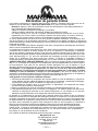
Emission System Parts
Exha
ust Emission
Carburetor
Muffler
Catalytic Converter
Ignition Coil / Magneto
Spark Plug
Air Filter
EGR Valve (piston)
Fuel Filter
Evaporative Emission
Fuel Tank
— US-4 —

― US -5 ―
Contents
Limited Warranty Statement .................................
Federal Emission Control .....................................
California Emission Control .................................
Contents ...............................................................
Introduction..........................................................
Safety .....................................................................
Operator Safety.................................................
Trimmer Safety ................................................
Fuel Safety ......................................................
Trimmer Operating Safety ...................................
Safety and Instruction Decals ......................................
Product Discription ......................................................
Assembly..............................................................
Loop Handle Installation .....................................
Connecting Stop Switch wires..................................
Installing Debris Shield .....................................
Installing Trimmer Head ..................................
Before Operation..................................................
Oil and Fuel ....................................................
Mixing Gasoline And Oil ...............................
Starting And Stopping ....................................
Operation .....................................................................
Operating Position .................................................
Cutting with Trimmer Head .................................
Maintenance ..............................................................
Idle Speed Adjustment ....................................
Air Filter ..............................................................
Fuel Filter ............................................................
Spark Plug ...........................................................
Cylinder Cooling Fins .......................................
Spark Arrester....................................................
Exhaust Muffler.................................................
Driveshaft.. ......................................................
Gen
eral Cleaning and Tightening ....................
Storage.......................................................................
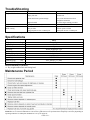
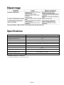
Troubleshooting ........................................................
Specifications ............................................................
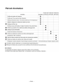
Maintenance Period ...................................................
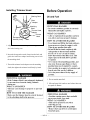
Introduction
Thank you for purchasing a MARUYAMA product.
Maruyama, it’s distributors, and dealers want you to be
completely satisfied with your new product. Please feel free to
contact your local Authorized Service Dealer for help with
service, genuine Maruyama parts, or other information you
may require.
Whenever you contact your Authorized Service Dealer
or the factory, always know the serial number of your
product. This number will help the Service Dealer or
Service Representative provide exact information about
your specific product. You will find the model and serial
number located in a unique place on the product
(Product Description on page US-8).
For your convenience, write the product model name
and serial number in the space below.
Read this manual carefully to learn how to operate and
maintain your product correctly. Reading this manual will
help you and others avoid personal injury and damage to the
product.
Although MARUYAMA designs, produces and markets safe,
state of the art products, you are responsible for using the
product properly and safely. (You are also responsible for
training persons who you allow to use the product about safe
operation.)
1
2
4
5
5
6
6
6
7
7
8
8
9
Assembling Engine and Driveshaft Assembly
.....
9
9
9
10
11
11
11
12
13
14
14
15
16
16
17
17
18
18
18
19
19
20
21
21
21
Model Name ___________________________
Serial No. ___________________________
Page US-
19

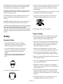
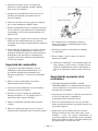
5. Always wear heavy, long pants, a long sleeved shirt, boots
and gloves. Do not wear loose clothing, jewelry, short
pants, sandals, or go barefoot. Secure hair so it is above
shoulder length.
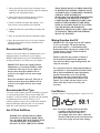
The MARUYAMA warning system in this manual identifies
potential hazards and has special safety messages that help
you and others avoid personal injury, even death.
DANGER, WARNlNG and CAUTION are signal words used
to identify the level of hazard. However, regardless of the
hazard, be extremely careful.
6. Never operate this Trimmer when you are tired, ill, or under
the influence of alcohol, drugs or medication.
7. Never start or run
the engine inside a closed room or
building. Breathing exhaust fumes can cause death.
DANGER signals an extreme hazard that will cause serious
injury or death if the recommended precautions are not
followed.
WARNING signals a hazard that ma
y cause serious injury or
death if the recommended precautions are not followed.
CAUTION signals a hazard that m
ay cause minor or moderate
injury if the recommended precautions are not followed. Two
other words are also used to high¬light information.
“Important” calls attention to special mechanical information
and “Note” emphasizes general information worthy of special
attention.
8. Keep handl
es clean of oil, fuel and dirt.
Trimmer Safety
Safety
1. Make sure the Trimmer is assembled correctly and that
the tool attachment is correctly installed and securely
fastened as instructed in the Assembly section.
Operator Safety
2. Inspect the Trimmer before each use. Replace dama
ged
parts. Check for fuel leaks. Make sure all fasteners are in
1.
place and tightened securely. Follow the maintenance
instructions be
ginning on page US-16.
Read and understand this Owner's/ Operator’s
Manual before using this product. Be thoroughly
familiar with the proper use of this product.
3. Make sure the cut
ting head does not rotate at engine
2.
idle speed. Refer to I
dle Speed Adjustment, page US-16.
Never allow children to operate the Trimmer. It
is
not a toy. Never allow adults to operate the unit
without first reading the Owner's/ Operator’s
Manual.
4. Inspect the
cutting head a
nd replace any parts that are
cracked, chipped or damaged before using the Trimmer.
3. Always wear eye protection that complies with
ANSI (American National
Standards Institute)
5. Make sure the shields is installed and positioned correctly
Z87-1.
before using the Trimmer.
6. Never use a cutting head or replacement parts that are not
approved by MARUYAMA.
7. Maintain the Trimmer according to the recommended
maintenance intervals
and procedures in the Maintenance
section on
page US-16.
8. Shut off
the engine and be certain the cutting head has
4. Alwa
ys
wear hearing protection.
completely stopped rotating before checking, inverting
the Trimmer, performing m
aintenance on or working on the
Trimmer.
9. If run
ning problems or excessive vibration occur, stop
immediately and inspect the unit for the cause.
― US - 6 ―

I
f the cause cannot be determined or is beyond your
Trimmer Operating Safety
ability to correct, return the Trimmer with tool
attachment to your servicing dealer for repair.
1. THIS TRIMMER CANCAUSE SERIOUS INJURIES.
Read the instructions carefully. Be familiar with all
controls and t
h
e proper use of the Trimmer.
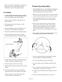
Fuel Safety
2. Make sure the φ3.5mm pin has been removed from the
1. Gasoline is highly flammable and must be handled
gearcase and boss adapter before you start the engine.
and store
d carefully
. Use a container approved for
fuel to store gasoline and/or fuel/oil mixture.
3. Avoid using the trimmer near rocks, gravel, stones
and similar material which can become dangerous
2. Mix and pour fuel outdoors, where there are no
projectiles.
sparks or flam
es.
4. Inspect
your work area before you begin. Rem
ove
3. Do
not smoke near fuel or Trimmer, o
r while
objects such as broken gla
ss, nails, wire
and rocks
usi
ng the T
rimmer.
which can beco
me
dangerous projectiles if thrown
b
y the Trimmer. Remove string, rope or sim
ilar
materi
als which can become
entangled in the cutting
head.
4. Do
not overfill the fuel tank. Stop filling 1/4-
1/2
inc
h (6 mm-13 mm) from the top of the tank.
5. Wipe
up any spilled fuel before starting the engi
ne.
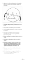
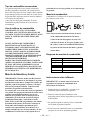
5. Keep children, by
standers and animal
s outside a 50 ft.
(15 m) radius from the operator and Trimmer.
6. Move the Trimmer at least 10 feet (3 m) away
from
the fueling location
before starting the engine.
6. If
you are approached while operating the Trimmer,
stop the engine and cutting head rotation.
7. Do
not remove the fuel tank cap while the engine is
7. Never allow children to operate the Trimmer.
running, or right after stopping the engine
.
8. Use the Trimmer onl
y in daylight or g
ood artificial
8. Allow
the engine to cool before refuelin
g.
light.
9. Drain t
he tank and run the engine dry before storing
9. Never operate the Trimmer without proper guards or
the unit.
other protective safety
devices in place.
10. St
ore fuel and Trimmer away from open flam
e,
10. Alway
s keep the Trimmer on the right side of yo
ur
spar
ks and excessive heat. Make sure fuel va
pors
body.
cannot reac
h sparks or open flames from wa
ter
11. Do n
ot raise the cutting head above waist level.
heaters, furnaces, electric motors, etc.
― US - 7 ―

― US-8 ―
12. Do not put hands or feet near or under any rotating
parts. Keep clear at all times. Keep al
l parts of
your body away from
the rotating cutting attachment
and
hot surfaces such as the muffler.
13. Keep firm footing and balance. Do not overreach.
14. Use the right to
ol for the job. Do not use the T
rimmer
for any job that is not recommended by Maruyama.
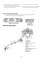
Safety and Instruction Decals
Safety decals and instructions are easily visible to the operator and are located near any area of
potential danger. Replace any decal that is damaged or lost.
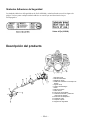
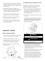
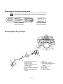
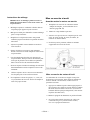
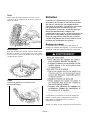
Product description
1. Shaft Assembly
2. Model Name
3. Loop Handle
4. Throttle Trigger and Stop Switch
5. Shaft Grip
6. Clutch Drum Housing
7. Engine
8. Serial Number (on side of engine)
9. Air filter
10. Fuel Tank
11. Throttle Cable and Stop Switch Wires
12. Trimmer head Shield
13. Trimmer head
14. Bearing Case
15. Safety Decal

― US-9 ―
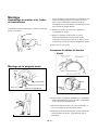
Assembly
Assembling Engine and Driveshaft
Assembly
The driveshaft, clutch d
rum housing and gearcase are
assembled. Attach the clutch drum housing to the
engine using the four M5 x 20 screws supplied with the
unit.
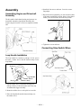
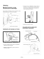
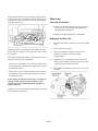
Loop Ha
ndle Installation
The loop ha
ndle kit contains a package of four screws
and nuts, a rubber sleeve and the bottom clamp for the
loop handle.
1. Slip t
he rubber sleeve around the shaft approxi-
mately 9 inches (22.8cm) from the end of the stop
switch/throttle trigger assem
bly
.
2. Rotate the rubber sleeve so the split is
to one side.
3. Place the loop handle and the bottom clamp over
the rubber
sleeve.
4. Install the four screws and nuts. Leave the screws
fingertight.
5. Reposition the loop handle up or down the driveshaft
to the m
ost comfortable position,
but no closer than 9
inches (22.8 c
m) from the end of the stop
switch.
6.
Tighten the screw
s and nuts.
Connecting Stop Switch Wires
Loop Handle
Screw
(
4
)
Bottom Clamp
Nut
(
4
)
Rubber Sleeve

― US-10 ―
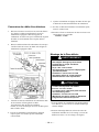
1. Install the plastic tube (packed with the driveshaft
assembly) around the throttle cable and stop
switch wires.
2. Plug the stop switch wires into the matching connect-
ors from the engine. Note that wire polarity is not
important.
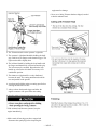
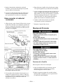
Connecting Throttle Cable
1. Loosen the knob and remove the air filter cover,
insert the throttle cable through the cable adjuster
sleeve on the carburetor bracket. Make sure theend
of the cable housing is seated positively in the
sleeve.
2. Position the slotted fitting on the carburetor so the
recessed hole for the cable lug is away from the
cable adjuster sleeve.
3. Rotate the carburetor throttle cam clockwise and
slip the throttle cable through the slot in the slotted
fitting, making sure the cable lug drops into
the recessed hole.
4. Operate the throttle trigger a few times to make
sure that it works correctly.
5. Adjust the cable adjuster sleeve so the stop on the
carburetor throttle cam just contacts the throttle
stop when the throttle trigger is fully depressed.
6. When the throttle cable is adjusted correctly, tighten
the locknut.
7.
Reinstall the air filter cover and tighten the knob.
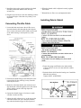
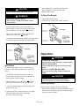
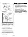
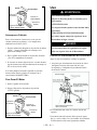
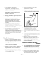
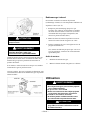
Installing Debris Shield
1. Fasten the string cutoff blade to the debris shield
with two M5x15 screws, hex nuts and lock washers
as shown.
2. Push the debris shield onto the bearing case. Install the
M6x40 screw and nut.
Tighten ONLY AS NEEDED

― US-11 ―
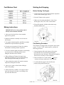
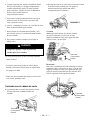
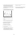
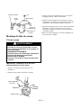
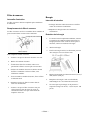
Installing Trimmer Head
1. Align the hole in the boss adapter with the guide
slot in the bearing case.
2. Insert the hexagonal wrench (3mm) into the hole and
guide slot in the boss adapter and bearing case to lock
the attaching shaft.
3. Thread the trimmer head adapter onto the attaching
shaft, then tighten the trimmer head firmly by hand.
Bearing Case
Boss
Adapter
Attaching
Shaft
Trimmer Head
Adapter
Trimmer
Head
Hexagonal
Wrench (3mm)

THAN THOSE MANUFACTURED FOR FUEL
3. Always shut off the engine before refueling. Never
rem
ove the fuel tank cap while the engine is running or
right after just stopping the engine.
STABIL
IZATION DURING STORAGE SUCH
AS MARUYAMA’S STABILIZER/ CONDITIO-
NER OR A SIMILAR PRODUCT.
MARUYAMA’S STABILIZER/CONDITIONER
4. Alway
s
open the fuel tank cap slowly to release
IS A PETROLE
UM DISTILLATE BASED
any possible overpressure inside the tank.
CONDITIONER/STABILIZER. MARUYAMA
DOES NOT RECOMMEND STABILIZERS
5. Do not overfill the fuel tank. Stop filling 1/4-1/2
WIT
H AN ALCOHOL BASE SUCH AS ETHA-
inch (6
mm-13 mm) from
the top of the tank.
NOL, ME
THANOL OR ISOPROPYL.
ADDITIVES SHOULD NOT BE USED TO TRY
6. Tighten the tank fuel cap carefully
but firmly after
TO ENHANCE THE POWER OR PERFOR-
refilling.
MANCE OF MACHINE.
7. Wipe up any
spilled fuel before starting the engi
ne.
Mixing Gasoline And Oil
8. Move the unit at least 10 feet (3 m) away from the
fueling l
ocation and fuel storage container before
IMPORTANT: The engine used on this Trimmer
starting the engine.
is of a 2-cycle design. The internal moving
parts of the engine, i.e., crankshaft bearings,
piston pin bearings and piston to cylinder wall
Recommended Oil Type
contact surfaces, require oil mixed with the
gasoline for l
ubrication.
Only use a two-cycle engine oil formulated for use in
high performance, air cooled two cycle engines.
Failure to add oil to the gasoline or failure to
MARUYAMA brand 2-cycle oil is formulated for use
mix oil with the gasoline at the appropriate
in high performance, air cooled two-cycle engines.
ratio will cause major engine damage which will
void your warranty.
IMPORT
ANT: Do not use National Marine
Manufacturer’s Association (NMMA) or BIA
For your fuel premix, use Maruyama Premium 2-
certified oils. This type of 2-cycle engine oil
cycle Oil Mix, or equivalent ISO-L-EGD & JASO
does not have the proper additives for air
FD oil with a minimum 89 octane high Quality
cooled, 2-cycle engines and can cause engine
gasoline. Maruyama 2-cycle oil is specially
damage.
formulated to meet the requirements of high-
perfor
mance, low-emission air-cooled 2-cycle
Do not use automotive motor oil. This type of
engines. Use of other oils may lead to service
oil does not have the proper additives for air
issues which may Not be covered by your
cooled, 2-cycle engines and can cause engine
warranty.
damage.
Recommended Fuel Type
Fuel Mixture
Use clean, fresh lead-free gasoline, including oxygenated
The fuel: oil ratio is 50 parts gasoline to 1 part oil or 50:1.
or reformulated gasoline, with an octane rating of 85
or higher. To
ensure freshness, purchase only the quantity
of gasoline that can be use
d in 30 days. Use of
lead-free ga
soline results in fewer combustion chamber
deposits and l
onger spark plug life. Use of premium
grade fuel is not necessary
or recommended.
Note: Never use a mixi
ng ratio less than 50:1
Use Of Fuel Additives
regardless of the oil package mixing
instructions. Ratios less than 50:1,
(for example, 60:1, 80:1, 100:1), reduce the
IMPORTANT: NEVER USE ALCOHOL,
amount of lubrication to the internal moving
GASOHOL CONTAINING MORE THAN
parts of the engine and can cause damage.
10% ALCOHOL BECAUSE ENGINE FUEL
SYSTEM DAMAGE COULD RESULT.
DO NOT USE FUEL ADDITIVES OTHER
― US - 12 ―

Fuel Mixture Chart Starting And Stopping
Before Starting The Engine
1. Fill the fuel tank as instructed in the Before Operation
section of this manual (page US-11).
2. Rest the Trimmer on the ground.
3. Make sure the cutting attachme
nt is clear of any
broken glass, nails, wire, rocks or other debris.
4. Keep all bystanders, children and animals away
from the wo
rking area.
Mixing Instructions
IMPORTANT: Never mix gasoline and oil
directly in the Trimmer fuel tank.
1. Always mix fuel and oil in a clean container
approved for gasoline.
2. Mark the container to identify it as fuel mix for
the Trimmer.
3. Use regular unleaded gasoline and fill the container
Cold Starting Procedure
with half the required amount of gasoline.
This Trimmer is equipped with a fuel prim
er and a choke
4. Pour the correct amount of oil into the container
system. To start a “cold” engine properly, perform the
following procedure:
then add the remaining amount of gasoline.
5. Close the container tightly and shake it m
omentarily
1. Pump the primer bulb at the bottom of the carbu-
to evenly mix the oil and the gasoline before
retor until fuel can be seen flowing through the
filling the fuel tank on the Trimmer.
fuel return line to the fuel tank. (Flowing fuel should be
almost clear, not foamy or full of bubbles.)
6. When refilling the Trimmer fuel tank, clean
around the fu
el tank cap to prevent dirt and debris
2. Move the choke lever to the closed (
) position
from entering the tank during cap removal.
and move the stop switch to the “ON” position.
7. Always shake the pre
mix fuel container momen-
3. Lock the throttle trigger in the fast-idle start
taril
y before filling the fuel tank.
position, then pull the starter grip.
8. Always use a spout or funnel when fueling to
reduce fuel spillage.
9. Fill the tank only to within 1/4-1/2 inch (6 mm-13
mm) from the top of the tank. Avoid filling to the
top of the tank filler neck.
― US - 13 ―

If the engine fails to start
after you follow the
CAUTION
above procedures, contact an authorized
After the engine starts, squeez
e and release the
throttle trigger to return it to the idle position, then
move the choke lever to the open (
) position.
If the engine stops running before you move the
choke lever to the open (
) position:
Go ahead and open the choke, pull the starter grip with
the throttle tigger positioned at Fast-idle position.
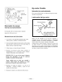
Hot Restart
To start an engine that is already warmed up (hot
restart), or if the ambient temperature exceeds 68°F
(20°C):
1. Pum
p the primer bulb at the bottom of the car-
buretor until fuel can be seen flowing through the
fuel return line to the fuel tank.
2. Mo
ve the choke lever to the open (
) position
and m
ove the stop switch to the “ON” position.
3. Leave the throttle trigger in the idle position and
pull the starter grip.
4. If the engi
ne fails to start after three to four
pulls,
follow the i
nstruction in the Cold Starting
Procedure section (this page).
MARUYAMA dealer.
• Do not pull the Starter rope all the way out.
To Stop The Engine:
WARNING
• Do not disassemble the Starter.
Please ask for an authorized MARU
YAMA
1. Release the throttle trigger.
2. Slide the s
top switch to
the “STOP” position.
service dealer.
Operation
WARNING
Operating Position
Before using the Trimme
r, check the following:
1. Make sure the Holding Tool (3mm hexagonal wrench)
has been
removed from the gearcase and boss adapter
beforeyou start the engine.
POTENTIAL HAZARD
・Foreign objects can be thrown by String Trimmer.
WHAT CAN HAPPEN
・Contact with thrown objects can cause personal
injury.
HOW TO AVOID THE HAZARD
・Never operate the String Trimmer without the
guard.
CAUTION
• Read the Safety instructions on page US-6
concerning proper use of the String Trimmer.
― US - 14 ―

― US-15 ―
2. The Trimmer must be on the operator’s right side.
3. The operator’s right hand should be holding the sh
aft
grip, with
his or her fingers on the throttl
e trigger. The
right arm
should be slightly
bent.
4. The left ha
nd should be holding the loop hand
le with
the fingers and thum
b fully enclosed around the grip.
The left arm may be extended. Repositi
on the loop
handle up
or down the driveshaft if necessary
for a
comfortable position.
5. The trimmer weight should be evenly
distributed
between the arm
s. The cutting attachment should
be
near and parallel to the ground.
6. Acceler
ate and hold the
engine at cutting speed before
entering the
materi
al to be cut.
7. Alway
s
release the throttle trigger and allow the
engine to return to idle speed when not cutting.
8. Stop the engine when moving
between work sites.
• If the tri
mmer head becomes ja
mmed, stop the
engine immediately
.
•
Make
certain all movi
ng parts have stopped and
disconnect th
e spark plug before inspecting the
equipment for damage.
• Never use a String Trimmer that has chipped, cracked
or broken
tri
mmer head.

Maintenance
Maintenance, replacement or repair of emission control
devices and systems may be performed by any repair
establishment or individual; however, warranty repairs
must be performed by a dealer or service center authorized
by Maruyama Manufacturing Company, Inc. The use of
parts that are not equivalent in performance and durability
to authorized parts may impair the effectiveness of the
emission control system and may have a bearing on the
outcome of a warranty claim.
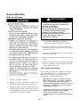
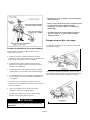
Three inchs (7,6c
m
)
abov
e
Groun
d
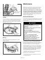
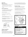
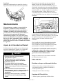
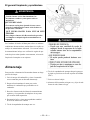
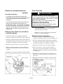
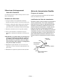
Idle Speed Adjustment
Scaling
This Trimmer is equipped with nonadjustable fuel mixture
carburetor. The engine idle speed is the only adjustment
for the operator.
To remove unwanted vegetation, hold the trimmer head
about 3 in. (7.6 cm) above the ground and at an angle.
Allow the tip of the line to strike the ground cutting the
vegetation off
at the surface.
Mowing
Keep the line parallel to the ground and use a gentle
side to side motion.
WARNING
POTENTIAL HAZARD
・Engine must be running to make carburetor
adjustments.
・When engine is running, cutting head is rotating
and other parts are moving.
WHAT CAN HAPPEN
・Contact with rotating cutting head or other
moving parts could cause serious personal injury
or death.
HOW TO AVOID THE HAZARD
・Keep hands, feet and clothing away from
attached tool and other moving parts.
・Keep all bystanders and pets away from unit
Three inchs (7,6c
m
)
abov
e
Groun
d
while making carburetor adjustments.
The cutting head may be rotating/moving during idle
speed adjustment. Wear the recommended personal
protective equipment and observe all safety instructions.
Keep hands and body away from the cutting head.
When the thr
ottle trigger is released, the engine should
return to an idle speed between 2700 and 3300 RPM, or
just below the clutch engagement speed. The Attached
Tool must not rotate/move and the engine should not
stall (stop running) at engine idle speed.
To adjust the
engine idle speed, rotate the idle speed
adjustment screw on the carburetor.
• Turn the idle speed scr
ew in (clockwise) to increase
the engine idle speed.
― US - 16 ―

• Turn the screw out (counterclockwise) to decrease
the engine idle speed.
Fuel Filter
If idle speed adjustment is necessary, and after
Maintenance Interval
adjustment the cutting head rotates or the engine
stalls, stop using the Trimmer immediately!
The fuel filter should be replaced after every 100 hours
of operation.
Contact your local authorized MARUYAMA Dealer for
assistance and servicing.
Fuel Filter Replacement
The fuel filter is attached to the end of t
he fuel pick-up
hose inside the fuel tank.
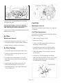
Air Filter
1. Make sure the fuel tank
is empty
.
Maintenance Interval
2. Remove the fuel cap.
• The air filter should
be cleaned daily, or mo
re
often when
working in extremely dusty
conditions.
3. Using a wi
re hook, gently pull the fuel
filter out
through the fuel filler opening.
• Repl
ace after every 100 hours of opera
tion.
4. Grasp the fuel hose next to the fuel filter fitting
Air Filter Cleaning
and remove the filter, but do not release the hose.
1. Loosen the knob and remove the air filter cover.
5. While still
holding on to the fuel hos
e, attach the
new fuel filter.
2. Remove the foam element and filter screen from
the air filter body.
6. Drop t
he new fuel filter back into the fuel tank.
3. Clean the foam
element
and filter screen with
7. Make sure that the fuel filter is not stuck in a corner
war
m, soapy water. Let the screen and element dry
of the tank, and that the fuel hose is not doubled
completely.
over (kinked) before refueling.
4. Apply a light coat of SAE 30 motor oil to the
foam element and squeeze out all excess oil.
5. Reassemble the filter screen, foam element and
to the air filter cover.
― US - 17 ―

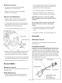
Spark Plug
Leaves, grass, dirt and debris buildup on the fins will
increase the operating temperature of the engine, which
can reduce engine performance and shorten engine life.
Maintenance Interval
• The spark plug should be removed from the engine
and checked after each 25 hours of operation.
Cooling Fin Cleaning
• Repl
ace the spark plug after every 100 hours of
1. With the engine at ambient (room) temperature,
operation.
loosen the knob and remove the air filter cover.
Spark Plug Maintenance
2. Twist the high tension lead boot on the spark plug
back and forth a couple of times to loosen the boot,
1. Twist the h
igh tension lead boot on the spark plug
then pull the boot off of the spark plug.
back and forth a couple of times to loosen the
bo
ot, then pull the boot off of the spark plug
.
3. Lo
osen the knob and lift off the cylin
der cover.
2. Rem
ove the spark plug.
4. Clean all dirt and debris from the cooling fins and
from
around the cylinder base.
3. Clean the electrodes with a stiff brush.
5. Reinstall the fan cover and the filter cover.
4. Adjust the
electrode air gap to .024-.0
28 in
(0.6-
0.7 mm
).
5. Replace the spark plug if it is oil-fouled, damaged,
or if the electrodes are wo
rn down.
6. Do no
t overtighten the spark plug wh
en installing.
The tighten
ing torque is 95-148 in. lbs.
(10.7-1
6.6 N·
m).
7. Always use only the specific heat range of spark plug.
This is particularly critical with today's lowem
ission
engines. For best results, use the exact replacement.
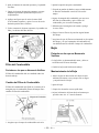
Cylinder Cooling Fins
Maintenance Interval
The cylinder cooling fins should be cleaned after every
25 hours of operation, or once a week, whichever
comes first. Air must flow freely around and through the
cylinder cooling fins to prevent engine overheating.
Air Filter Cover
Cylinder Cover
High Tension
Lead Boot
Knob
Cooling
Fins
Knob
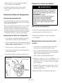
Spark Arrester
WARNING
POTENTIAL HAZARD
• Muffler surface becomes hot whenTrimmer
in operation and remains hot for
some time after the engi
ne is shut off.
WHAT CAN HAPPEN
• Contact with hot muffler surfaces could cause
a burn.
HOW TO AVOID THE HAZARD
• Make sure the muffler is cool before inspecting
and cleaning the spark arres
ter.
― US - 18 ―

2. Twist the high tension lead boot on the spark plug
Maintenance Interval
back and forth a couple of times to loosen the boot,
•
The spark arrester should be inspected and
then p
ull the boot off of the spark plug.
cleaned afte
r every
25 hours of use.
3. Lo
osen the knob and lift off the cylin
der cover.
• Repl
ace the screen if it cannot be thoroughl
y
cleaned, or if it is damaged.
4. Rem
ove the spark arrester (see spark arrest
er
maintenanc
e), Clean the muffler with a stiff brush.
IMPOR
TANT: Don’t use solvent for cleaning
Spark Arrester Maintenance
inside of muffler, because of the catalytic converter
1. With the engine at am
bient (room) temp
erature,
in muffler.
loosen the
knob and remove the air filter cover.
Be careful n
ot to allow any dirt or debris to fall
2. Twist the
high tension lead boot on the spark plug
into the exhaust port, as this can cause engine
back and forth a couple of times to loosen the boot,
damage.
then pull the boot off of the spark plug.
5. Reinstall the spark arrester and tail onto muffler,
3. Loosen the knob and lift off the cylinder cover.
then reinstall and tighten the two socket head
screws.
6. Reinstall the cy
linder cover and the air filter cover.
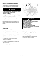
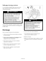
Driveshaft
Maintenance Interval
The flexible driveshaft should be lubricated aftereach
30 hours of use.
Driveshaft Lubrication
Loosen the two screws on the bearing case and remove the
bearing case. The inner flexible driveshaft is easily removed
by gripping the end securely and pulling it from the drive-
4. Remove and clean the tail, gasket and spark arrester
shaft tube. Lubricate the entire length the flexible driveshaft
with a safety solvent and a stiff brush.
If any part
and insert it into the driveshaft tube. Twist the flexible shaft
while pushing to insure that it
seats correctly into the drive-
shaft coupler. Re-install the bearing case onto the driveshaft
cannot be thoroughl
y cleaned, it must be replaced.
5. Reinstall the spark arres
ter and tail onto the muffler, tube and tighten the two screws.
then reinstall and tighten the two socket headscrews.
6. Reinstall the cy
linder cover and the
air filter cover.
Exhaust Muffler
Maintenance Interval
The muffler should be inspected and cleaned after each
100 hours of use.
Muffler Maintenance
1. With the engine at ambient (room) temperature,
loosen the
knob and remove the air cleaner cover.
― US - 19 ―
La page est en cours de chargement...
La page est en cours de chargement...
La page est en cours de chargement...
La page est en cours de chargement...
La page est en cours de chargement...
La page est en cours de chargement...
La page est en cours de chargement...
La page est en cours de chargement...
La page est en cours de chargement...
La page est en cours de chargement...
La page est en cours de chargement...
La page est en cours de chargement...
La page est en cours de chargement...
La page est en cours de chargement...
La page est en cours de chargement...
La page est en cours de chargement...
La page est en cours de chargement...
La page est en cours de chargement...
La page est en cours de chargement...
La page est en cours de chargement...
La page est en cours de chargement...
La page est en cours de chargement...
La page est en cours de chargement...
La page est en cours de chargement...
La page est en cours de chargement...
La page est en cours de chargement...
La page est en cours de chargement...
La page est en cours de chargement...
La page est en cours de chargement...
La page est en cours de chargement...
La page est en cours de chargement...
La page est en cours de chargement...
La page est en cours de chargement...
La page est en cours de chargement...
La page est en cours de chargement...
La page est en cours de chargement...
La page est en cours de chargement...
La page est en cours de chargement...
La page est en cours de chargement...
La page est en cours de chargement...
La page est en cours de chargement...
La page est en cours de chargement...
La page est en cours de chargement...
La page est en cours de chargement...
La page est en cours de chargement...
La page est en cours de chargement...
La page est en cours de chargement...
La page est en cours de chargement...
La page est en cours de chargement...
La page est en cours de chargement...
La page est en cours de chargement...
La page est en cours de chargement...
-
 1
1
-
 2
2
-
 3
3
-
 4
4
-
 5
5
-
 6
6
-
 7
7
-
 8
8
-
 9
9
-
 10
10
-
 11
11
-
 12
12
-
 13
13
-
 14
14
-
 15
15
-
 16
16
-
 17
17
-
 18
18
-
 19
19
-
 20
20
-
 21
21
-
 22
22
-
 23
23
-
 24
24
-
 25
25
-
 26
26
-
 27
27
-
 28
28
-
 29
29
-
 30
30
-
 31
31
-
 32
32
-
 33
33
-
 34
34
-
 35
35
-
 36
36
-
 37
37
-
 38
38
-
 39
39
-
 40
40
-
 41
41
-
 42
42
-
 43
43
-
 44
44
-
 45
45
-
 46
46
-
 47
47
-
 48
48
-
 49
49
-
 50
50
-
 51
51
-
 52
52
-
 53
53
-
 54
54
-
 55
55
-
 56
56
-
 57
57
-
 58
58
-
 59
59
-
 60
60
-
 61
61
-
 62
62
-
 63
63
-
 64
64
-
 65
65
-
 66
66
-
 67
67
-
 68
68
-
 69
69
-
 70
70
-
 71
71
-
 72
72


dans d''autres langues
- English: Maruyama B23C Owner's manual
- español: Maruyama B23C El manual del propietario
Documents connexes
-
Maruyama B23C Le manuel du propriétaire
-
-
-
-
Maruyama M42BK-QC Le manuel du propriétaire
-
-
-
-
-