OZ LIFTING PRODUCTS OZ4000EC Le manuel du propriétaire
- Taper
- Le manuel du propriétaire

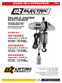
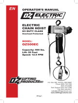
ELECTRIC
CHAIN HOIST
H3 DUTY CLASS
Overload Protected
MODELS:
OZ1000EC
Capacity: 1000 lbs.
Lift: 20 Feet
Speed: 20 FPM
OZ2000EC
Capacity: 2000 lbs.
Lift: 10 Feet
Speed: 13 FPM
OZ4000EC
Capacity: 4000 lbs.
Lift: 10 Feet
Speed: 6.5 FPM
P.O. Box 845, Winona, MN 55987
Phone (800) 749-1064
(507) 474-6250
Tech Support (507) 457-3346
Fax (507) 452-5217
ozliftingproducts.com
OPERATOR’S MANUAL - EN

TABLE OF CONTENTS
Pg.2 .....................Warranty
Pg.3 .....................Dimensions and Specications / Safety Precautions / Product Warnings
Pg.5 .....................Terms and Summary / Operation Personnel
Pg.6 .....................Installation
Pg.9 .....................Maintenance
Pg.11 ....................Inspection
Pg.17 ....................Troubleshooting
Pg.18 ....................Repair Parts Ordering Instructions
Pg.19 ....................Wiring Diagram
Pg.20 ....................Parts Breakdown
Pg.21 ....................Parts List
WARRANTY
OZ Lifting Products LLC® guarantees this product to be free of defects in materials and workmanship
for one year from the date of shipment.
This warranty does not apply to products that show signs of misuse, overloading, alteration, improper
maintenance or negligence. The normal wear and tear of moving parts is excluded from the warranty.
Moving parts are dened as brake discs, wire rope and other wear components that are subject to use
conditions. This warranty does not cover any costs related to removal of this product, lost time, or any
other incidental or consequential damages/costs resulting from the claimed defects.
If this product fails during the rst year of operating due to defective materials or workmanship, it will be
repaired or replaced at the discretion of OZ Lifting Products LLC®. Any product subject to a warranty
claim must be returned, prepaid, to an authorized OZ Lifting Products LLC® warranty depot along with
proof of purchase. Upon repair, the product will be returned to the customer free of charge. If no defect
is found, the customer will be responsible for return shipping costs. The product’s warranty will be
effective for the remainder of the original warranty period (one year from shipment date).
OZ Lifting Products LLC® will not be held liable for the following arising from the use of this product:
injuries to persons or property, death, incidental, consequential, or contingent damages, whether
negligent or deliberate. It is the sole responsibility of the owner to install and operate the product
properly and safely.
This is OZ Lifting Products LLC®‘s only written warranty. This warranty is in lieu of all other warranties
implied by law such as merchantability and tness. The sale of products from OZ Lifting Products LLC®
under any other warranty or guarantee, expressed or implied, is not authorized.
NOTE: OZ Lifting Products LLC® has the right to alter the design of or discontinue the
production of any product without prior notice.
P.O. Box 845, Winona, MN 55987
Phone (800) 749-1064
(507) 474-6250
Tech Support (507) 457-3346
Fax (507) 452-5217
www.ozliftingproducts.com
EN pg.2

EN pg.3
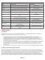
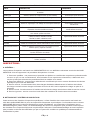
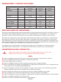
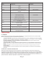
DIMENSIONS AND SPECIFICATIONS:
MODEL SPECIFICATION
Model OZ1000EC OZ2000EC OZ4000EC
Lifting Top Layer 1000 lbs. 2000 lbs. 4000 lbs.
Load Chain Falls 1 1 2
Chain 6.3mmX6m 7.1mm x 3m 7.1mm x 3m
Lifting Speed 20 FPM 13 FPM 6.5 FPM
Motor 1.8HP 2.4HP 2.4HP
Motor KW 110V 1400W/10A 1800/13A 1800/13A
Duty Cycle 18 min. 18 min. 18 min.
Pendant Length 19’ 19’ 19’
Power Cord Length 15’ 15’ 15’
Net Weight 53 lbs. 64 lbs. 84 lbs.
SAFETY PRECAUTIONS:
Throughout the manual are safety precautions and instructions for awareness, along with information
on potential hazards. Due to the complexities of this hoist and the environment in which it operates,
situations may arise which are not directly discussed in detail in this manual.
This manual is provided as a guide to personnel involved with the operation and maintenance of the
hoist equipment. Only trained and qualied personnel can operate and maintain this equipment. We
recommend that all personnel who operate and maintain the hoist review and become familiar with
this manual. In addition, we recommend that this manual be kept readily available for reference before
beginning operation, maintenance and testing of this equipment.
Most accidents involving hoist are the result of violating safety rules during operation and/or lack of
inspection and maintenance procedures.
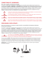
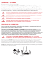
PRODUCT WARNINGS:
Warning indicates an imminently hazardous situation which, if not avoided,
could result in death or serious injury, and property damage.
DON’Ts
DON’T operate the hoist until you have read the Operating, Maintenance and parts manual.
DON’T use the hoist to lift, support or transport people.
DON’T lift loads over personnel.
DON’T operate the hoist until all personnel are clear of the supported load.
DON’T operate a hoist which has been modied without the manufacturer’s approval or without
certication that it is in conformity with ANSIIASME B30 volumes.
DON’T operate a hoist unless the load slings or other approved single attachments are properly sized
and seated in the hook saddle.
DON’T use load chain as a sling or wrap the chain around the load.
DON’T use hoist with twisted, kinked, damaged or worn load chain.
DON’T operate a hoist on which the safety place cards or decals are missing or illegible.
DON’T operate a damaged or malfunctioning hoist.
DON’T remove or obscure the warning labels on the hoist.
WARNING

EN pg.4
DON’T lift more than the rated load for the hoist.
DON’T apply the load unless load chain is properly seated in the chain sprocket(s).
DON’T operate hoist when it is restricted from forming a straight line from hook to hook in the direction
of loading.
DON’T operate beyond the limits of the load chain travel.
DON’T leave the load unattended unless specic precautions have been taken.
DON’T apply the load to the tip ofthe hook or to the hook latch.
DON’T attempt to lengthen the load chain or repair the damaged load chain.
DON’T apply load if bearing prevents equal loading on all load supporting chains.
DON’T operate unless load is centered under the hoist properly.
DON’T operate a hoist until it has been securely attached to a suitable support.
DON’T allow the load chain or hook to be used as an electrical or welding ground.
DON’T allow the load chain or hook to be touched by a live welding electrode.
DO’s
DO shut down a hoist immediately if it malfunctions or performs unusually and report such malfunction.
DO warn personnel of an approaching load.
DO make sure that the hoists limit switches function properly.
DO take up slack carefully - make sure the load is balanced and the load holding action is secure before
continuing.
DO protect the hoist’s load chain from weld splatter or other damaging contaminants.
PRODUCT CAUTIONS:
Caution indicates a potentially hazardous situation which, if not avoided,
may result in minor or moderate injury, or property damage.
DON’Ts
DON’T adjust or repair the hoist unless qualied to perform such adjustments or repairs.
DON’T allow the hoist to be subjected to sharp contact with other hoist, structures or objects
through misuse.
DON’T allow your attention to be diverted from operating the hoist.
DON’T use the hoist overload limiting clutch to measure the load.
DO’s
DO inspect the hoist regularly, replace damaged or worn parts and keep appropriate records
of maintenance.
DO lubricate load chain per hoist manufacturer’s recommendations.
DO use Mechanics Hoist CH recommended parts when repairing the hoist unit.
DO check brake function by tensioning the hoist prior to each lift operation.
DO maintain rm footing or be otherwise secured when operating the hoist.
DO make sure the hook latches are closed and not supporting any parts of the load.
DO use hook latches. Latches are to retain slings, chains, ect. under slack conditions only.
DO avoid swinging the load or hook.
DO make sure the load is free to move and will clear all obstructions.
DO make sure the hook travel is in the same direction as shown on the controls.
CAUTION

EN pg.5
TERMS AND SUMMARY:
Notice, Caution, Warning and Danger
This manual contains important information to help you properly install, operate and maintain the
OZ1000EC, OZ2000EC and OZ4000EC for maximum performance and safety purpose. Although you
may be familiar with this equipment or similar equipment, it is very strongly recommended that you read
this manual before attempting to operate, install or maintain the product. Please study the contents
thoroughly before putting the HOIST in operation. The following signal words are used to identify the
degree or level of hazard seriousness. Follow all instructions and warnings, failure to operate equipment
as directed in manual may cause injury or property damage.
Notice is used to notify people of installation, operation or maintenance information which is
important but not directly hazard related.
Warning indicates an imminently hazardous situation which, if not avoided, could result in
death or serious injury and property damage.
Caution indicates a potentially hazardous situation which, if not avoided, may result in minor
or moderate injury or property damage.
Caution indicates a potentially hazardous situation which, if not avoided, may result in minor
or moderate injury, or property damage.
OPERATION PERSONNEL:
For independent operation or maintenance of chain hoist, the owner may only employ
persons as following:
This manual contains important information to help you properly install, operate and maintain the
OZ1000EC, OZ2000EC and OZ4000EC for maximum performance and safety purpose. Although you
may be familiar with this equipment or similar equipment, it is very strongly recommended that you read
this manual before attempting to operate, install or maintain the product. Please study the contents
thoroughly before putting the HOIST in operation. The following signal words are used to identify the
degree or level of hazard seriousness. Follow all instructions and warnings, failure to operate equipment
as directed in manual may cause injury or property damage.
OZ1000EC, OZ2000EC and OZ4000EC operators should read and fully comprehend
this entire manual and all warnings on the hoist before use. If this manual is not read and
followed completely, injuries may occur.
All Persons MUST: Be trained in proper operation and in dealing with potential malfunctions of lifting
equipment. Abstain from use of alcohol, medications, or drugs while operating. Avoid operation while
tired or distracted. Avoid operation if they have a history of seizures or other medical issues that may
interfere with operation.
NOTE: Prior to operation, ensure that the hoist is in proper working condition and maintenance records
are up to date.
NOTICE
WARNING
WARNING
CAUTION
DANGER

EN pg.6
INSTALLATION:
A. PRE--INSTALLATION CHECKS:
1. Check for transit damage.
2. Check that all external wiring is in good order.
3. Check that the load chain is in good order.
4. Check that all fasteners and joints are tight and secure.
5. Check the capacity of the lifting unit and bottom block.
B. POWER SUPPLY SYSTEM:
To insure proper operation, to avoid damage to the hoist and electrical system, and to reduce the risk of
electrical shock or re, the branch circuit supplying power to the hoist must:
1. Effectively ground the hoist in accordance with the National Electrical Code and other applicable
codes. Proper grounding provides a path with the least resistance for the electrical current to travel
reducing the risk of electrical shock. The standard power cord is equipped with a three prong plug,
used with our 110V unit. Make sure that the receptacle opening that receives the longest prong is
properly grounded.
2. Be in accordance with the National Electrical Code (ANST/NFPA-70) and applicable National,
State and Local codes.
3. Include a disconnecting means capable of being locked in the ‘open’ position.
4. Have ample capacity to prevent excessive voltage drop during starting and operation. When
determining the size of branch circuit components and conductors, special consideration should be
given to the starting current amps (approximately three times that shown on the hoist identication
plate) and the length of the conductors. As a minimum, the system should be rated for 20 amps
and the system should have #14 AWG or larger, wiring.
5. Include slow blow type fuses or inverse trip time circuit breakers to permit the hoist to start and
accelerate the load.
Failure to properly ground the hoist presents the danger of electric shock.
To avoid injury: Permanently ground the hoist as instructed in this manual.
Failure to provide a proper power supply system for the hoist may cause hoist damage and
offers the potential for a re.
To avoid injury: Provide the hoist with a 20 amp, minimum, over current protected power
supply per the National Electrical Code (ANSI/NFPA 70) and applicable local codes as
instructed in this manual.
C. CONNECTION TO THE ELECTRICAL SUPPLY:
An adequate supply system is required along the total length of travel (where appropriate). The supply
voltage and frequency at which the hoist operates, is marked on the motor rating plate. It is imperative to
check before connecting the unit that these gures correspond with those of the supply voltage.
WARNING
WARNING

EN pg.7
D. MOUNTING THE HOIST:
Hang the hoist from its intended support. The structure used to support the hoist must have sufcient
strength to withstand several times the load amount. If you are not sure of the weight the structure can
hold, consult a registered engineer and the local building codes.
Suspending the hoist from an inadequate support could allow the hoist and load to fall and
cause personal injury and/or property damage.
To avoid injury: Make sure that the structure has sufcient strength to withstand several
times the hoist and its rated load amount. Using the upper hook, hang the hoist from the
support. Make sure the hoist is solidly held in the uppermost part of the hook arc and the
latch is tightly against the hook tip.
E. LOAD CHAIN:
The chain should feed smoothly into and away from the hoist and hook block (1/2 ton and 1 ton). If the
chain binds, jumps or is noisy, First clean and lubricate the chain, iftroub1e persists inspect chain and
mating parts for wear, distortion and other damages.
F. LOAD CHAIN LUBRICATION:
Always lubricate load chain weekly or more frequently depending on severity of service. Lubricate load
chain with a light coat of Lubriplate Bar and Chain Oil 10-R (Fiske Bros. Rening Co.) or equal lubricant.
Be sure the lubricant reaches the bearing surfaces between the links. Remove the excess oil from the
chain.
Used motor oils contain unknown carcinogenic materials.
To avoid health problems: Never use used motor oils as a chain lubricant. Only use
Lubriplate Bar and Chain Oil 10-R as a lubricant for the load chain.
G. HOOK AND EYE SUSPENSION HOISTS:
The suspension point should be of a correct size to admit the top hook or eye of the hoist and allow it
to rest properly on the saddle. It must be adequate to support the hoist while it is being operated at its
maximum capacity (safe working load).
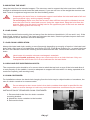
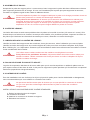
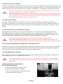
H. CHAIN CONTAINER:
For installations where the slack chain hanging from the hoist may be objectionable or hazardous, the
use of a chain container is recommended.
Do not attempt to store more chain in the chain container than what is specied for the
hoist or serious damage to hoist may result and hazardous conditions may be created.
INSTALLATION OF STANDARD CHAIN CONTAINER:
1. Remove both bolts from the chain container
mounting bracket.
2. Attach the chain container to the bracket.
3. Reinsert the bolts.
WARNING
WARNING
WARNING

EN pg.8
I. TEST AND OPERATIONAL CHECKS:
On completion of installation, but before the hoist is put into regular service, the following procedure
should be carried out:
1. Record the hoist’s Code, Lot and Serial Number from the name plate on the hoist.
2. Check that the hoist is properly installed to either a xed point or trolley, whichever applies.
3. If hoist is installed on a trolley, ensure that:
- The trolley is properly installed on the beam.
- The stops for the trolley are correctly positioned and securely installed on the beam.
4. Isolate the power supply.
5. Check that all mechanical and electrical joints and connections are tight and secure.
6. Check that all nuts, bolts and split pins (cotter pins) are securely fastened.
7. Conrm proper operation:
- Before operating read and become familiar with this manual.
-Before operating check to ensure that the hoist (and trolley) meet the Inspection, Testing
and Maintenance requirements of ANSI!ASME B30.16.
-Before operating check that nothing will interfere with the full range of the hoist’s
(and trolley’s) operation.
8. Switch on the power supply.
9. Run lightly with no load, throughout the full extent of the hoist and check that the operation is
smooth at all times.
10. Check the operation of the hoist brake, run under light load and full load conditions.
Check supply voltage before everyday use. If the voltage varies more than 10% of the rated
value, electrical devices may not function normally.
Conrm the adequacy of the rated capacity for all slings, chains, wire ropes and all other
lifting attachments before use. Inspect all load suspension members for damage prior to
use and replace or repair all damaged parts.
Verify and correct all chain irregularities prior to operating the hoist.
J. UNPACKING:
Once package has been opened, carefully inspect the hoist frame, hooks, chain and control station for
damage that may have occurred during shipment.
Operating a unit with obvious external damage may cause load to drop and could result in
personal injury and/or property damage.
To avoid injury: Carefully check unit for external damage prior to installation.
Make sure to check that the power supply to which the hoist is to be connected matches the information
shown on the identication plate located on the bottom of the hoist.
BEFORE USING THE HOIST, FILL IN THE INFORMATION BELOW:
Model No.: _______________________________________
Serial No.: _______________________________________
Purchase Date: ___________________________________
WARNING
WARNING
WARNING
CAUTION

EN pg.9
MAINTENANCE:
A. CHAIN INSPECTION:
1. First clean chain with a non-caustic/non-acid type solvent and make a link by link inspection for
nicks, gouges, twisted links, weld splatter, corrosion pits, striations (minute parallel lines), cracks in
weld areas, wear and stretching. A chain with any of these defects must be replaced before use.
2. When checking the chain for wear, check the part of the chain that goes through the lift wheel
of the hoist most often. Check the interlink area of the chain links for the point of maximum wear.
Measure and record the stock diameter at this point of the link. Then measure stock diameter in the
same area on a link that does not pass through the lift wheel. Compare these two measurements.
If the stock diameter of the worn link is 0.010 inches or more, than the stock diameter of the
unworn link, the chain must be replaced.
3. Check the chain for stretch with a vernier caliper. Select an unused, unstretched section of
chain then measure and record the length. Measure and record the same length on a worn section
of chain. Obtain the amount of stretch and wear by subtracting the measurement of the unworn
section from the worn section. If the result is greater than 0.145 inch, the chain must be replaced.
4. Use only a ‘Knife-edge’ caliper to eliminate the possibility of false reading by not measuring full
pitch length.
5. These chains are specially heat treated and hardened, they should never be repaired.
IMPORTANT: Do not use replaced chain for other purposes such as lifting or pulling. Load chain may
break suddenly without visual deformation. For this reason, cut replaced chain into short lengths to
prevent use after disposal.
NOTE: A worn chain can be an indication of worn hoist components. For this reason, the hoist’s
chain guide, hook block and lift wheel should be examined for wear and replaced as necessary when
replacing worn chain.
Use of commercial or other manufactures’ chain and parts to repair OZ Electric Chain
Hoists may cause load loss. To avoid injury: Use only factory supplied replacement load
chain and parts. Chain and parts may look alike, but factory original chain and parts are
made of specic materials or processed to achieve specic properties.
A. CUTTING THE CHAIN:
The load chain is hardened and is difcult to cut. The following methods are recommended when cutting
a length of new chain from stock or cutting off worn chain. (Always wear eye protection when cutting the
load chain.)
1. Use a 7” minimum diameter by 1/8” thick abrasive wheel (or type recommended by your wheel
supplier) that will clear the adjacent links.
2. Use a grinder and nick the link on both sides, then secure the link with a vise and break off the
chain link with a hammer.
Cutting chain can produce ying particles.
To avoid health problems:
- Wear eye protection.
- Place shield over chain to prevent ying objects.
WARNING
WARNING

EN pg.10
C. LUBRICATION:
1. Load Chain: The full length of the chain must be lubricated, including where the chain passes
over the chain wheel(s). Ensure that the contact points between the links (I.E. the chain saddles) are
adequately lubricated. A small amount of lubrication will greatly increase the life of the load chain.
DO NOT allow the chain to run dry. Keep the chain clean and lubricate the chain at regular intervals
with Lubriplate Bar and Chain Oil 10-R or equal lubricant. Normally, weekly lubrication and cleaning
is satisfactory, but under hot and dirty conditions, it may be necessary to clean the chain at least
once daily and lubricate the chain several times between cleanings. When lubricating the chain,
apply sufcient lubricant to obtain natural run-off and full coverage, especially in the interlink area.
Used motor oils contain known carcinogenic materials.
To avoid health problems: Never use used motor oils as a chain lubricant. Only use
Lubriplate Bar and Chain Oil 10-R as a lubricant for the load chain.
2. Gearbox: For ambient temperature of approx., 50 F to 122 F, a gear oil of Mm /S at 104 F, with
mild high-pressure additives should be used. Examples of the oil types that can be used are:
Din 51502 Clp 220
E.G. Bp Energol Gr-Xp 20
Esso Spartan Ep 220
Shell Omala Oil 220
Mobil gear 630
Aral Degol Bg 220
3. Important: The bottom block must not touch the oor; if necessary adjust the position of the
chain stop on the slack end of the chain.
The lubricants used for the OZ Electric Chain Hoist may contain hazardous materials that
mandate specic handling and disposal procedures.
To avoid contact and contamination: Handle and dispose of lubricants only as directed in
applicable material safety data sheets and in accordance with applicable local, state and
federal regulations.
D. TESTING:
Before using, all altered, repaired or used hoists that have not been operated for the previous 12 months
must be tested by the user for proper operation.
1. Test the unit without a load and then test the unit with a light load of 50 pounds (23 kg) times
the number of load chain supporting parts to be sure that the hoist operates properly and that the
brake holds the load when control is released.
2. Next test with a load of 125% of the rated capacity. In addition, hoists in which load sustaining
parts have been replaced, you should test the load with 125% of rated capacity by or under an
appointed person and a written report prepared for record purposes.
3. In accordance with the CMAA 78, it is required to have a 100% load test preformed every
four years.
The hoist must only be inspected and maintained by qualied, competent and trained
personnel.
WARNING
CAUTION

EN pg.11
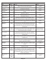
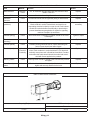
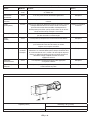
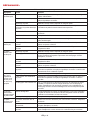
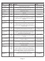
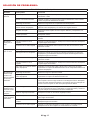
Table 7-1 Lubrication Chart
PART DESCRIPTION FREQUENCY
Cables Check control cables and strain relief elements Before each shift
Clutch Check operation of the slipping clutch (if tted) Before each shift
Pendant Check control pendant housing for damage Before each shift
Hook Check suspension eye/suspension hook assembly After 50-200 service hours
Electrical Check electrical switch gear and wiring Before each shift, Monthly
Hook Check tight t of securing bolts on load hook assembly Before each shift, After 50-200 service
hours
Chain Check ends of chain/chain bag to ensure they are
secure
Before each shift
Chain Lubricate chain, under normal usage
Lubricate chain, under heavy usage
After 50-200 service hours
Oil Check oil level and change oil (if needed) Before each shift
Hook Check hooks for cracks, deformation, pitting and wear After 50-200 service hours
Clips/Bolts/Nuts Check securing elements for tight t and corrosion After 50-200 service hours
Bottom Block Lubricate chain sprocket bearing and check for a tight
t of securing bolts.
After 50-200 service hours
Brakes Check operation of brakes After 50-200 service hours
Brake Check brake stroke, brake disc and adjust brake as
required
After 50-200 service hours
INSPECTION:
A. GENERAL:
The inspection procedure is based on ANSI/ASME B30.16. The following denitions are from ANSI/
ASME B30.16 and pertain to the inspection procedure below.
1. Qualied Person: A person who, by possession of a recognized degree or certicate of
professional standing, or who, by extensive knowledge, training and experience has successfully
demonstrated the ability to solve or resolve problems relating to the subject matter at work.
2. Designated Person: A person assigned or selected as being competent to perform the specic
duties to which he/she is assigned.
3.
Normal Service: A distributed service which involves operation with randomly distributed loads within
the rated load limit or uniform loads less than 65% of rated load for not more than 25% of the time.
4. Heavy Service: A service which involves operation within the rated load limit which exceeds
normal service.
5.
Severe Service: A service which involves normal or heavy service with abnormal operating conditions.
B. INSPECTION METHODS AND CRITERIA:
This section covers the inspection of specic items. The list of items in this section is based on those
listed in ANSI/ASME B30.16 for the Frequent and Periodic Inspection. In accordance with ANSI/ASME
B30 volumes listed under the General heading on the previous pages, these inspections are not intended
to involve disassembly of the hoist. Rather, disassembly for further inspection would be required if
frequent or periodic inspection results so indicate. Such disassembly and further inspection should only
be performed by a certied or qualied person trained in the disassembly and re-assembly of the hoist.

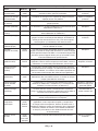
Table 8-1 Hoist Inspection Methods and Criteria
Item Method Criteria Action
Functional operat-
ing mechanisms
Visual,
Auditory
Mechanisms should be properly adjusted and should not
produce unusual sounds when operated.
Repair or replace as
required
Braking System
Operation
Function Braking distance with rated capacity should not exceed ap-
proximately ve chain links.
Repair or replace as
required
Hooks (surface
condition)
Visual Should be free of signicant rust, weld splatter, deep nicks or
gouges.
Replace
Hooks (stretch) Measure The “D” dimension should not exceed the measured value for
discard from Table 8-3.
Replace
Hooks (fretting
wear)
Measure The “F” and “T” dimensions should not be less than discard
value listed in Table 8-3.
Replace
Hooks (yoke as-
sembly)
Visual Should be free of signicant rust, weld splatter, nicks or
gouges. Holes should not be elongated, fasteners should not
be loose and there should be no gap between mating parts.
Tighten or replace as
required
Hooks (bent shank
or neck)
Visual Shank and neck portions of hook should be free of deforma-
tions.
Replace
Hooks (hook
latches)
Visual,
Function
Latch should not be deformed. Attachment of latch to hook
should not be loose. Latch spring should not be missing and
should not be weak. Latch movement should not be stiff-
when depressed and released latch should snap smartly to its
closed position.
Replace
Hooks (swivel
bearing)
Visual,
Function
Bearing parts and surfaces should not show signicant wear.
They should be free of dirt, grime and deformations. Hook
should rotate freely with no roughness.
Clean/Lubricate, or
replace as required
Load Chain (sur-
face condition)
Visual Should be free of rust, nicks, gouges, dents and weld spatter.
Links should not be deformed or show signs of abrasion.
Surfaces where links bear on one another should be free of
signicant wear.
Replace
Load Chain
(lubrication)
Visual,
Auditory
Entire surface of each link should be coated with lubricant and
free of dirt/grime. Chain should not emit cracking noise when
hoisting a load.
Clean/ Lubricate
Load Chain (pitch
and wire diameter)
Measure The “G” dimension should not be greater than maximum value
listed in Table 8-4. The “E” dimension should not be less than
minimum value listed in Table 8-4.
Replace. Inspect Load
Sheave by qualied
personnel
Load Chain
(reeving)
Visual Chain should be reeved properly through load sheave. Chain,
cushion rubbers, washers and stoppers should be installed
properly.
Reeve/ Install chain
properly
Chain Container Visual Container should not be damaged. Brackets should not be
deformed or missing.
Replace
Housing and
Mechanical Com-
ponents
Visual,
Auditory,
Vibration,
Function
Hoist components including load blocks, suspension housing,
chain attachments, clevises, yokes, suspension bolts, shafts,
gears, bearings, pins and rollers should be free of cracks,
distortion, signicant wear and corrosion. Evidence of same
can be detected visually or via detection of unusual sounds or
vibration during operation.
Replace
Bolts, Nuts and
Rivets
Visual,
Check with
proper
tool
Bolts, nuts and rivets should not be loose. Tighten or replace as
required
EN pg.12

Table 8-1 Hoist Inspection Methods and Criteria
Item Method Criteria Action
Motor Brushes Measure,
Visual
The “B” dimension should not be less than minimum value
listed in Table 8-2.
Replace
Cushion Rubber Visual Should be free of signicant deformation. Replace
Contactor
Contacts
Visual Contacts should be free of signicant pitting or deterioration. Replace
Pendant
(switches)
Function Depressing and releasing push buttons should make and
break contacts in switch contact block and result in cor-
responding electrical continuity or open circuit. Push buttons
should be interlocked either mechanically or electrically to
prevent simultaneous energization of circuits for opposing
motions. Example: Up and Down
Repair or replace as
necessary
Pendant (wiring) Visual Wire connections to switches in pendant should not be loose
or damaged.
Tighten or repair
Pendant
(housing)
Visual Labels denoting functions should be legible. Replace
Pendant (labels) Visual Pendant housing should be free of cracks and mating sur-
faces of parts should seal without gaps.
Replace
Pendant (cord) Visual,
Electrical
Continuity
Surface of cord should be free from nicks, gouges and abra-
sions. Each conductor in cord should have I 00% electrical
continuity even when cord is exed back and forth. Pendant
cord strain relief cable should absorb the entire load associ-
ated with forces applied to the pendant.
Replace
Warning Labels Visual Warning labels should be afxed to the hoist and they should
be legible.
Replace
Hoist Capacity
Label
Visual The label that indicates the capacity of the hoist should be
legible and securely attached to the hoist.
Replace
Table 8-2 Motor Brush Dimensions
Capacity (Ton) “B” Dimension (inches)
Discard
1/2 to 2 .315 in.
EN pg.13

EN pg.14
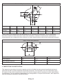
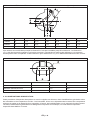
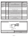
Table 8-3 Top Hook & bottom Hook Dimensions (Inches)
Capacity T/B a b c d e g
1000 lbs T/B 1.14 .76 1.02 .76 1.09 0.87
2000 lbs T/B 1.30 .91 1.14 .91 1.56 1.22
4000 lbs T/B 1.77 1.22 1.61 1.22 1.81 1.50
These values are nominal since the dimension is not controlled to a tolerance. The “D” dimension
should be measured when the hook is new, this becomes a reference measurement. Subsequent
measurements are compared to this reference to make determinations about hook deformation/stretch.
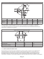
Table 8-4 Chain Wear Dimensions
Standard Dimension d Ø 6.3 Ø 7.1
Limit Dimension mm Ø 5.7 Ø 6.4
Wear Standard Dimension p 19.1 20.2
Wear Limit Dimension mm 20 21
C. INSPECTION CLASSIFICATION:
The inspection procedure for hoist in regular service is divided into two general classications based
upon the intervals at which inspection should be performed. The intervals in turn are dependent upon
the nature of the critical components of the hoist and the degree of their exposure to wear, deterioration
or malfunction. The two general classications are designated as Frequent and Periodic, with respective
intervals between inspections as dened below.

EN pg.15
Initial Inspection: Prior to initial use, all new, altered or modied hoist shall be inspected by
a designated person to ensure compliance with the applicable provisions of this manual.
FREQUENT INSPECTIONS - Frequent inspections are visual examinations by the operator or other
designated personnel with interval per the following criteria.
1. Normal Service- Monthly
2. Heavy Service - Weekly to Monthly
3. Severe Service- Daily to Weekly
4. Special or Infrequent Service - As recommended by a qualied person before and after each
occurrence.
PERIODIC INSPECTIONS - Periodic inspections are visual inspections by a designated person with
interval per the following criteria.
1. Normal Service - Yearly
2. Heavy Service- Semi-Annually
3. Severe Service - Quarterly
4. Special or Infrequent Service- As recommended by a qualied person before the rst occurrence.
D. FREQUENT INSPECTION:
Inspections should be made on a Frequent basis in accordance with Table 8-5, “Frequent Inspection.”
Included in these Frequent Inspections are observations made during operation for any defects or
damage that might appear between Periodic Inspections. Frequent Inspections shall be made by a
designated person to ensure that the hoist is maintained in safe working condition.
Table 8-5 Frequent Inspection
1. Check all functional operating mechanisms for maladjustment and unusual sounds.
2. Check the operation of the limit switch and associated components.
3. Check the hoist braking system for proper operation.
4. Check the hooks in accordance with ANSI/ASME B30.10.
5. Check the hook latch operation.
6. Check the Load Chain in accordance with Section 8B
7. Check the Load Chain reeving.
E. PERIODIC INSPECTION:
Inspections should be made on a Periodic basis in accordance with Table 8-6, “Periodic Inspection.”
Evaluation and resolution of the results of Periodic Inspections shall be made by a designated person to
ensure that the hoist is maintained in safe working condition.
Periodic Inspection: For inspections where load suspension parts of the hoist are
disassembled, a load test per ANSI/ASME B30.16 must be performed on the hoist after it is
re-assembled and prior to its return to service.
CAUTION
WARNING

EN pg.16
Table 8-6 Periodic Inspection
1. Complete the requirements of Frequent Inspection.
2. Check to ensure there is no evidence of loose bolts, nuts or rivets.
3. Check to ensure there is no evidence of damage or excessive wear of load and idler sheaves.
4. Check to ensure there is no evidence of damage to hook retaining nuts or collars and pins, and welds or rivets used to
secure the retaining members.
5. Check to ensure the warning label is properly attached to the hoist and legible.
6. Check to ensure the function labels on the pendant control stations are legible.
7. Check to ensure there is no evidence of worn, corroded, cracked or distorted parts such as load blocks, suspension
housing, chain attachments, clevises, yokes, suspension bolts, shafts, gears, bearings, pins and rollers.
8. Check to ensure there is no evidence of damage to the supporting structure or trolley, if used.
9. Check to ensure there is no evidence of damage to the end connections of the load chain.
10. Check to ensure there is no evidence of excessive wear on motor or load brake.
11. Check to ensure there is no electrical apparatus for signs of pitting or any deterioration of visible controller contacts.
F. OCCASIONALLY USED HOIST:
Hoists that are infrequently used shall be inspected as follows before placing the hoist in service:
1. Hoist idle more than one month, less than one year: Inspect per Frequent Inspection.
2. Hoist idle more than one year: Inspect per Periodic Inspection.
G. INSPECTION REPORTS:
Hoists that are infrequently used shall be inspected as follows before placing the hoist in service:
1. A long range chain inspection program should be established and should include records of an
examination of the chains that are removed from service. To create a relationship between visual
observation and actual condition of the chain.
2. Dated inspection reports and records should be maintained for the hoist Periodic Inspection
intervals. These records should be stored where they are available to personnel involved with the
inspection, maintenance or operation of the hoist.

EN pg.17
TROUBLESHOOTING:
Table 8-7 Troubleshooting Guide
Symptom Cause Remedy
Hoist will not
operate
Loss of power Check circuit breakers, switches, fuses and connections on power lines/
cable.
Wrong voltage or frequency Check voltage and frequency of power supply against the rating on the
nameplate of the motor.
Hoist overload Reduce load to within rated capacity of hoist.
Improper, loose or broken wire
in the hoist electrical system
Shut off power supply, check wiring connections on hoist control panel
and inside push button pendant.
Brush wear Inspect both motor brushes per Table 8-2 and replace if necessary.
Fuses burned out Replace fuses.
Motor burned out Replace motor frame/stator, shaft/rotor and any other damaged parts.
Hoist lifts but
will not lower
Faulty switch in pendant Check electrical continuity. Check electrical connections. Replace or
repair as needed.
Broken conductor in pendant
cord
Check the continuity for each conductor in the cable. If one is broken,
replace the entire cable.
Hoist lowers
but will not lift
Hoist overload Reduce load to within rated capacity of hoist.
Worn friction clutch Repair by a qualied person trained in the repair of hoists and proper
friction clutch adjustment procedures. Replace as needed.
Broken conductor in pendant
cord
Check the continuity for each conductor in the cable. If one is broken,
replace the entire cable.
Faulty switch in pendant Check electrical continuity. Check electrical connections. Replace or
repair as needed
Low voltage in hoist’s power
supply
Determine cause of low voltage and bring to within plus or minus 5% of
the voltage specied on the motor nameplate. The voltage should be
measured at the hoist contactor.
Hoist will
not lift rated
load or does
not have the
proper lifting
speed
Hoist overload Reduce load to within rated capacity.
Low voltage in hoist’s power
supply
Determine cause of low voltage and bring to within plus or minus 5% of
the voltage specied on the motor nameplate. The voltage should be
Faulty friction clutch If abnormal operation or slippage occurs do NOT attempt to disassem-
ble or adjust the Mechanical Load Brake with Friction Clutch. Replace
the worn or malfunctioning Mechanical Load Brake with Friction Clutch
as an assembly with a new, factory adjusted part.
Load drifts
excessively
when hoist is
stopped
Motor demagnetized Motor demagnetizing is generally caused from using the hoist beyond
its duty rating. Replace stator assembly and reduce usage to comply
with the duty rating stated.
Improper gear oil Replace oil with the correct gear oil.
Hoist operates
intermittently
Loose connection in circuit Check all wires and terminals for bad connections. Replace as needed.
Collectors making poor contact Check movement of spring loaded arm, weak spring, connections and
shoe. Replace as needed.
Broken conductor in pendant
cord
Check for intermittent continuity in each conductor in the pendant cord.
Replace the entire pendant cord if continuity is not constant.

EN pg.18
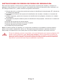
REPAIR PARTS ORDERING INSTRUCTIONS:
This parts and instruction manual contains information required to install and maintain your hoist. To
insure prompt service, each repair parts order should be placed with OZ Lifting Products, LLC, and must
contain the following information:
1. Serial number and Model number from the OZ hoist name plate, located on the side of the hoist.
2. Hoist capacity from the hoist name plate, located on the side of the hoist.
3. Voltage, Amp and Horse Power from the hoist name plate, located on the side of the hoist.
4. Hoist Speed from the hoist name plate, located on the side of the hoist.
5. Part name from the part list.
6. Item number of part from the part list.
7. Part number from the part list.
8. Quantity of parts requested.
Note: When ordering replacement parts, it is recommended that consideration be given to the need for
also ordering such items as gaskets, fasteners, seals, etc. These items may be damaged or lost during
disassembly or just unt for future use because of deterioration from age or service.
Use of commercial or other manufactures’ chain and parts to repair OZ Hoists may cause
load loss. To avoid injury: Use only factory supplied replacement load chain and parts.
Chain and parts may look alike, but factory original chain and parts are made of specic
materials or processed to achieve specic properties.
WARNING

EN pg.19
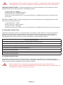
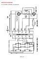
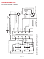
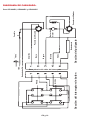
WIRING DIAGRAM:
For OZ1000EC, OZ2000EC and OZ4000EC

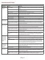
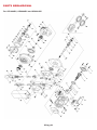
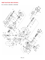
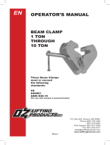
PARTS BREAKDOWN:
EN pg.20
For OZ1000EC, OZ2000EC and OZ4000EC
La page est en cours de chargement...
La page est en cours de chargement...
La page est en cours de chargement...
La page est en cours de chargement...
La page est en cours de chargement...
La page est en cours de chargement...
La page est en cours de chargement...
La page est en cours de chargement...
La page est en cours de chargement...
La page est en cours de chargement...
La page est en cours de chargement...
La page est en cours de chargement...
La page est en cours de chargement...
La page est en cours de chargement...
La page est en cours de chargement...
La page est en cours de chargement...
La page est en cours de chargement...
La page est en cours de chargement...
La page est en cours de chargement...
La page est en cours de chargement...
La page est en cours de chargement...
La page est en cours de chargement...
La page est en cours de chargement...
La page est en cours de chargement...
La page est en cours de chargement...
La page est en cours de chargement...
La page est en cours de chargement...
La page est en cours de chargement...
La page est en cours de chargement...
La page est en cours de chargement...
La page est en cours de chargement...
La page est en cours de chargement...
La page est en cours de chargement...
La page est en cours de chargement...
La page est en cours de chargement...
La page est en cours de chargement...
La page est en cours de chargement...
La page est en cours de chargement...
La page est en cours de chargement...
La page est en cours de chargement...
La page est en cours de chargement...
La page est en cours de chargement...
La page est en cours de chargement...
La page est en cours de chargement...
-
 1
1
-
 2
2
-
 3
3
-
 4
4
-
 5
5
-
 6
6
-
 7
7
-
 8
8
-
 9
9
-
 10
10
-
 11
11
-
 12
12
-
 13
13
-
 14
14
-
 15
15
-
 16
16
-
 17
17
-
 18
18
-
 19
19
-
 20
20
-
 21
21
-
 22
22
-
 23
23
-
 24
24
-
 25
25
-
 26
26
-
 27
27
-
 28
28
-
 29
29
-
 30
30
-
 31
31
-
 32
32
-
 33
33
-
 34
34
-
 35
35
-
 36
36
-
 37
37
-
 38
38
-
 39
39
-
 40
40
-
 41
41
-
 42
42
-
 43
43
-
 44
44
-
 45
45
-
 46
46
-
 47
47
-
 48
48
-
 49
49
-
 50
50
-
 51
51
-
 52
52
-
 53
53
-
 54
54
-
 55
55
-
 56
56
-
 57
57
-
 58
58
-
 59
59
-
 60
60
-
 61
61
-
 62
62
-
 63
63
-
 64
64


OZ LIFTING PRODUCTS OZ4000EC Le manuel du propriétaire
- Taper
- Le manuel du propriétaire
dans d''autres langues
Documents connexes
-
 OZ LIFTING PRODUCTS OZ500EC Le manuel du propriétaire
-
 OZ LIFTING PRODUCTS OZ075-15LHOP Le manuel du propriétaire
-
 OZ LIFTING PRODUCTS OBH1000 Le manuel du propriétaire
-
 OZ LIFTING PRODUCTS OZ05PBTA-16 Le manuel du propriétaire
-
 OZ LIFTING PRODUCTS OZ3BC Le manuel du propriétaire
-
 OZ LIFTING PRODUCTS OBH230-WALL Le manuel du propriétaire


Autres documents
-
Milwaukee 9676-20 Manuel utilisateur
-
Milwaukee 9683-20 Manuel utilisateur
-
Ingersoll-Rand ELK25-1ND25 Information produit
-
Power Fist 8873150 Le manuel du propriétaire
-
-
-