Mitsubishi Electric PZ-62DR-E Manuel utilisateur
- Taper
- Manuel utilisateur

1. Safety Precautions
●Thoroughly read the following safety precautions prior to installation.
●Observe these precautions carefully to ensure safety.
●After reading this manual, pass it on to the end user to retain for future reference.
●Keep this manual for future reference and refer to it as necessary. This manual should be made available to those who repair or
relocate
the controller. Make sure that the manual is passed on to any future users.
WARNING
CAUTION
WARNING Indicates a risk of death or serious injury.
CAUTION Indicates a risk of serious injury or structural damage.
General precautions
2105875H17001
English
Lossnay Remote Controller
PZ-62DR-E
Installation Manual For distribution to dealers and contractors
All electric work must be performed by qualified personnel.
Do not install the unit in a place where large amounts of oil, steam,
organic solvents, or corrosive gases, such as sulfuric gas, are present
or where acidic/alkaline solutions or sprays are used frequently. These
substances can compromise the performance of the unit or cause
certain components of the unit to corrode, which can result in electric
shock, malfunctions, smoke, or fire.
To reduce the risk of shorting, current leakage, electric shock,
malfunctions, smoke, or fire, do not wash the controller with water
or any other liquid.
To reduce the risk of electric shock, malfunctions, smoke or fire, do
not operate the switches/buttons or touch other electrical parts with
wet hands.
To reduce the risk of injury or electric shock, before spraying a
chemical around the controller, stop the operation and cover the
controller.
To reduce the risk of injury or electric shock, stop the operation and
switch off the power supply before cleaning, maintaining, or inspecting
the controller.
Properly install all required covers to keep moisture and dust out of the
controller. Dust accumulation and water can cause electric shock,
smoke, or fire.
To reduce the risk of injury, keep children away while installing,
inspecting, or repairing the controller.
To reduce the risk of fire or explosion, do not place flammable
materials or use flammable sprays around the controller.
To reduce the risk of damage to the controller, do not directly spray
insecticide or other flammable sprays on the controller.
To reduce the risk of electric shock or malfunctions, do not touch
the display or buttons with a pointy or sharp object.
To reduce the risk of injury and electric shock, avoid contact with
sharp edges of certain parts.
To avoid injury from broken glass, do not apply excessive force on the
glass parts.
To reduce the risk of injury, wear protective gear when working on the
controller.
This installation manual describes how to install the Lossnay Remote Controller.
Please be sure to read this installation manual before proceeding with the installation.
Failure to follow the instructions may result in equipment damage.
For information on how to wire and install the Lossnay units, refer to the Lossnay unit Installation Manual.
After the installation, hand over this manual to users.
Eng-1

- 2 -
WARNING
CAUTION
WARNING
CAUTION
WARNING CAUTION
Precautions during installation
Precautions during wiring
Precautions for moving or repairing the controller
Additional precautions
Do not install the controller where there is a risk of leaking flammable
gas. If flammable gas accumulates around the controller, it may ignite
and cause a fire or explosion.
Properly dispose of the packing materials. Plastic bags pose
suffocation hazard to children.
Take appropriate safety measures against earthquakes to prevent
the controller from causing injury.
To prevent injury, install the controller on a flat surface strong
enough to support its weight.
To reduce the risk of shorting, current leakage, electric shock,
malfunctions, smoke, or fire, do not install the controller in a place
exposed to water or in a condensing environment.
Controller must be installed by qualified personnel according to the
instructions detailed in the Installation Manual.
Improper installation may result in electric shock or fire.
When attaching the cover and the top casing to the bottom casing,
push it until it they click into place. If they are not properly locked
into place, they may fall, causing personal injury, controller
damage, or malfunctions.
To reduce the risk of damage to the controller, malfunctions, smoke, or
fire, do not connect the power cable to the signal terminal block.
Properly secure the cables in place and provide adequate slack in
the cables so as not to stress the terminals. Improperly connected
cables may break, overheat, and cause smoke or fire.
To reduce the risk of injury or electric shock, switch off the main
power before performing electrical work.
All electric work must be performed by a qualified electrician
according to the local regulations, standards, and the instructions
detailed in the Installation Manual. Capacity shortage to the power
supply circuit or improper installation may result in malfunction,
electric shock, smoke, or fire.
To reduce the risk of current leakage, overheating, smoke, or fire,
use properly rated cables with adequate current carrying capacity.
To reduce the risk of electric shock, shorting, or malfunctions, keep
wire pieces and sheath shavings out of the terminal block.
To reduce the risk of shorting, current leakage, electric shock, or
malfunctions, keep the cables out of contact with controller edges.
To reduce the risk of electric shock, malfunctions, or fire, seal the
gap between the cables and cable access holes with putty.
The controller should be repaired or moved only by qualified
personnel. Do not disassemble or modify the controller.
Improper installation or repair may cause injury, electric shock, or fire.
To reduce the risk of shorting, electric shock, fire, or malfunction,
do not touch the circuit board with tools or with your hands, and do
not allow dust to accumulate on the circuit board.
To avoid damage to the controller, use appropriate tools to install,
inspect, or repair the controller.
This controller is designed for exclusive use with the Lossnay by
Mitsubishi Electric. The use of this controller for other systems or for
other purposes may cause malfunctions.
Take appropriate measures against electrical noise interference
when installing the Lossnay in hospitals or facilities with radio
communication capabilities. Inverter, high-frequency medical,
or wireless communication equipment as well as power generators
may cause the Lossnay to malfunction. Lossnay may also
adversely affect the operation of these types of equipment by
creating electrical noise.
To avoid malfunctions, do not bundle power cables and signal
cables together, or place them in the same metallic conduit.
To prevent malfunctions, do not remove the protective film or the
circuit board from the casing.
To avoid damage to the controller, do not overtighten the screws.
Use a flat-head screwdriver with a blade width of 4-7 mm (5/32-9/
32 inch). The use of a screwdriver with a narrower or wider blade
tip may damage the controller casing.
To prevent damage to the controller casing, do not force the driver
to turn with its tip inserted in the slot.
To avoid discoloration, do not use benzene, thinner, ethanol,
hypochlorous acid or chemical rag to clean the controller. To clean the
controller, wipe with a soft cloth soaked in water with mild detergent, wipe
off the detergent with a wet cloth, and wipe off water with a dry cloth.
Eng-2

- 3 -
2
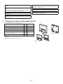
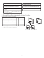
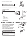
. Component names and supplied parts
The following parts are included in the box.
*4 The front cover (*1) is already installed on the top case (*2) at factory
shipment.
*5 Remote controller cable is not included.
To avoid damage to the controller, provide protection against static
electricity.
Do not use solderless terminals to connect cables to the terminal
block.
Solderless terminals may come in contact with the circuit board and
cause malfunctions or damage the controller cover.
To avoid damage to the controller, do not make holes on the
controller cover.
Do not install the controller on the control panel door.
Vibrations or shocks to the controller may damage the controller or
cause the controller to fall.
Hold the cables in place with clamps to prevent undue force from
being applied to the terminal block and causing cable breakage.
To prevent cable breakage and malfunctions, do not hang the top
controller casing hang by the cable.
Parts name Qty. Appearance
Remote controller (front cover) 1 Right figure *1
Remote controller (top case) 1 Right figure *2
Remote controller (bottom case) 1 Right figure *3
Roundhead cross slot screws M4×30 2
Wood screw 4.1×16
(for direct wall installation) 2
1Simple manual
*4
Bottom case *3
Top case *2
Front cover *1
Do not install in the highly humid place such as inside the shower
room etc. The relative humidity range shall be 30% to 90% without
condensation.
Eng-3

- 4 -
3
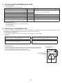
.Field-supplied parts/Required tools
(1) Field-supplied parts
The following parts are field-supplied parts.
(2) Field-supplied tools
●Flat-tip screwdriver (Width: 4-7 mm (5/32-9/32 inch))
●Knife or Nipper
●Miscellaneous tools
4
. Selecting an installation site
This remote controller is for the wall installation. It can be installed either in the switch box or directly on the wall. When performing direct
wall installation, wires can be thread through either back or top of the remote controller.
(1)Selecting an installation site
To prevent injury, install the controller on a flat surface strong enough to support its weight.
setoN.ytQeman straP
1xob hctiws elbuoD
Not required for direct wall installationyrasseceNtiudnoc latem nihT
yrasseceNgnihsub dna tun
kcoL
llaw a gnola elbac rellortnoc etomer gnituor rof deriuqeRyrasseceNrevoc elbaC
elbanosaeRyttuP
yrasseceNrohcna ylloM
Remote controller cable
(Use a 0.3 mm² (AWG22) 2-core sheathed cable.) Necessary
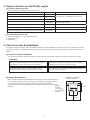
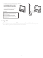
(2)Installation space
Leave a space around the remote controller as shown in the figure at right, regardless of
whether the controller is installed in the switch box or directly on the wall. Removing the
remote controller will not be easy with insufficient space.
Also, leave an operating space in front of the remote controller.
Important
30
(1-3/16)
30
(1-3/16)
30 (1-3/16)
120 (4-3/4)
120 (4-3/4)
120 (4-3/4)
External dimensions of
remote controller
unit: mm(in)
Minimum required space
around the remote
controller
To reduce the risk of shorting, current leakage, electric shock,
malfunctions, smoke, or fire, do not install the controller in a place
exposed to water or in a condensing environment.
To avoid deformation and malfunction, do not install the remote
controller in direct sunlight or where the ambient temperature may
exceed 40ºC (104ºF) or drop below 0ºC (32ºF).
To reduce the risk of malfunctions and damage to the controller,
avoid installing the remote controller on an electrically conductive
surface, such as an unpainted metal sheet.
Do not install in the highly humid place such as inside the shower
room etc. The relative humidity range shall be 30% to 90% without
condensation.
Eng-4

- 5 -
5
. Installation/Wiring work
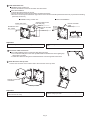
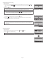
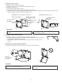
4 Connect the remote controller cable to the terminal block on the bottom case.
Peel off 6 mm of the remote controller cable sheath as shown in the figure below, and thread the cable from behind the bottom
case. Thread the cable to the front of the bottom case so that the peeled part of the cable cannot be seen behind the bottom
case. Connect the remote controller cable to the terminal block on the bottom case.
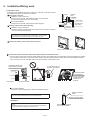
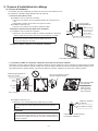
(1) Installation work
Controller can be installed either in the switch box or directly on the wall. Perform
the installation properly according to the method.
1 Drill a hole in the wall.
Installation using a switch box
●Drill a hole in the wall, and install the switch box on the wall.
●Connect the switch box to the conduit tube.
Direct wall installation
●Drill a hole in the wall, and thread the cable through it.
2 Seal the cable access hole with putty.
Installation using a switch box
●Seal the remote controller cable access hole at the connection of switch
box and conduit tube with putty.
3 Prepare the bottom case of the remote controller.
Direct wall installation
●Seal the hole through which the cable is threaded with putty.
To reduce the risk of electric shock, malfunctions, or fire, seal the
gap between the cables and cable access holes with putty.
Wall Conduit
tube
Locknut
Switch box
Seal the gap
with putty.
Remote
controller cable
Bushing
Bottom case
Front cover and top case
10 (13/32)
6 (1/4)
unit: mm(in)
Sheath
Thread the sheath part
of the cable to the front.
Thread the cable.
Front Back
2-core wire must not
be seen on the back.
Connect the cable.
(non-polarized)
Connect the cable
so that the cable
sheath is not
pinched.
To reduce the risk of electric shock, shorting, or malfunctions, keep
wire pieces and sheath shavings out of the terminal block.
Important
Do not use solderless terminals to connect cables to the terminal
block.
Solderless terminals may come in contact with the circuit board and
cause malfunctions or damage the controller cover.
Seal the gap with putty.
Route the cable behind
the remote controller.
Remote controller
cable
Eng-5

- 6 -
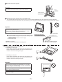
5 Install the bottom case.
Installation using a switch box
●Secure at least two corners of the switch box with screws.
Direct wall installation
●Thread the cable through the groove.
●Secure at least two corners of the remote controller with screws.
●Be sure to secure top-left and bottom-right corners of the remote controller (viewed from the front) to prevent it from lifting.
(Use molly anchor etc.)
7 Route the wire to the top case.
Connect the connector on the bottom case to the connector on the top case.
6 Cut out the cable access hole.
Direct wall installation (when running the cable along the wall)
●Cut out the thin-wall part on the cover (indicated with the shaded area in the right figure)
with a knife or a nipper.
●Thread the cable from the groove behind the bottom case through this access hole.
Installation using a switch box Direct wall installation
Seal the cable access
hole with putty.
Double switch box
Roundhead cross
slot screws Remote controller
cable
Wood
screw
Remote controller
cable
Thread the cable
through the groove.
Refer to 2.
Refer to 4.
Refer to 4.
To avoid damage to the controller, do not overtighten the screws. To avoid damage to the controller, do not make holes on the controller
cover.
Important
Securely connect the
connectors.
To prevent malfunctions, do not remove the protective film or the
circuit board from the casing.
To prevent cable breakage and malfunctions, do not hang the top
controller casing by the cable.
Important
Eng-6

- 7 -
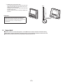
8 Route the wire to the top case.
9 Install the front cover and top case on the bottom case.
Two mounting tabs are at the top of the top case. (A cover is already installed on the case at the time of factory shipment.)
Hook those two tabs onto the bottom case, and click the top case into place. Check that the case is securely installed and not lifted.
(2) Uninstalling the front cover and top case
1Uninstalling the front cover
Insert a flat-tip screwdriver into either of the two latches at the
bottom of the remote controller, and move it in the direction of
the arrow as shown in the figure at right.
2Uninstalling the top case
Insert a flat-tip screwdriver into either of the two latches at the
bottom of the remote controller, and move it in the direction of
the arrow as shown in the figure at right.
Hold the cables in place with clamps to prevent undue force from
being applied to the terminal block and causing cable breakage.
Important
Clamp
Insert the wire.
When attaching the cover and the top casing to the bottom casing,
push it until it they click into place.
If they are not properly locked into place, they may fall, causing
personal injury, controller damage, or malfunctions.
Important
Direct wall installation (when running the cable along the wall)
●Thread the cable through the access hole at the top of the
remote controller.
●Seal the cut-out part of the cover with putty.
●Use a cable cover.
Installation is complete.
Follow the instructions below when uninstalling them.
No lifting
Wall
Seal the gap with putty.Use a cable cover.
Thread the cable through the
top of the remote controller.
Use a flat-head screwdriver with a blade width of 4-7 mm (5/32-9/
32 inch). The use of a screwdriver with a narrower or wider blade
tip may damage the controller casing.
To prevent damage to the controller casing, do not force the driver
to turn with its tip inserted in the slot.
To prevent damage to the control board, do not insert the driver
into the slot strongly.
Important
Eng-7

- 8 -
6
. Important
Refer to section 9 “Initial setting menu” in this Manual for remote controller main/sub setting.
At the time of factory shipment, protective sheet is on the operation interface of the front cover.
Peel off the protective sheet on the operation interface prior to use.
3Installing the cover and top case
Two mounting tabs are at the top of the top case.
Hook those two tabs onto the bottom case, and
click the top case into place.
Install the cover on the top case in the same way
as with the top case.
Check that the top case is securely installed and
not lifted.
When attaching the cover and the top casing to the
bottom casing, push it until it they click into place.
If they are not properly locked into place, they may fall,
causing personal injury, controller damage, or
malfunctions.
Important
No lifting
Wall
Eng-8

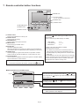
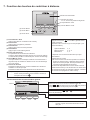
7. Remote controller button functions
(3) RETURN button
(4) MENU button
(2) SELECT button
(5) Backlit LCD
(7) Function buttons
F1, F2, F3, and F4 from the left
(6) ON/OFF lamp
(1) ON/OFF button
Main
Main display:
Cursor
Main menu
User options
Commissioning
Maintenance
F1 F2 F3 F4
Cursor
(1) ON/OFF button
Press to turn ON/OFF the Lossnay unit.
(2) SELECT button
Press to save the setting.
(3) RETURN button
Press to return to the previous screen.
(4) MENU button
Press to bring up the Main menu.
(5) Backlit LCD
Operation settings will appear.
When the backlight is off, pressing any button turns the backlight on
and it will stay lit for a certain period of time depending on the screen.
(6) ON/OFF lamp
This lamp lights up in green while the unit is in operation. It blinks
while the remote controller is starting up or when there is an error.
(7) Function buttons
Use to select the Ventilation mode and fan speed on the Main display.
Use to select items on other screens.
Button operations on the Main menu
Note: When the backlight is off, pressing any button turns the backlight
on and does not perform its function. (except for the button)
Note: If the function is not set in the function button, the function
button guide will not be displayed.
Pressing the button will bring up the Main menu as
shown below.
(Refer to section 8.(2) “Main display” for details.)
User options *1, *3
Commissioning *1, *2, *3
Maintenance *1, *3
*1 Refer to the Instructions Book for details.
*2 Explained in this manual.
*3 If no buttons are pressed for 10 minutes (2 hours on
some screens), the screen will automatically return to
the Main display. Any settings that have not been saved
will be lost.
The available items on the menu depend on the connected
Lossnay unit model. For items not described in the manuals
that are enclosed with the remote controller, refer to the
manuals that came with the Lossnay units.
Move the cursor to the desired function with the and but-
tons, and press the button to go to the next page. Password
may be required.
The function of the , , and buttons will appear on
the setting screens.
Button function guide will appear at the bottom of the screens.
Eng-9

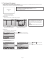
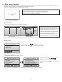
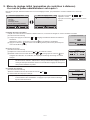
8. Turning on the power
Make sure that the remote controller is properly installed according to the instructions in the Installation Manual and that the Lossnay unit
installation has been completed before turning on the power.
(1) When the power is turned on, the following screen will appear.
(2) Main display
After the successful startup, the Main display will appear.
(3) Main menu
Press the MENU button, this screen appear.
(4) Commissioning menu
You can use Commissioning menu.
Main display
(While the unit is not in operation)
Press the , button to move the cursor.
Press the button to go to the next screen.
Press the , , , button to move the
cursor or page.
Press the button to go to the next screen.
• Administrator password is required. See 9. (5) Administrator password.
Main display
(While the unit is in operation)
Note:
• Only the first time, the «Language selection» screen will be appeared.
• The product will not start-up without language selection.
• See 9. (6) Language selection.
Lossnay
Outdoor
2°C
Return
2 °C
Fan Mode
Auto
Lossnay 12: Sun 12: Sun
Main
Main display:
Cursor
Main menu
User options
Commissioning
Maintenance
Commissioning menu 1/2
Initial setting
Airflow
Auto bypass
External input
Service
Cursor Page
Main menu:
Commissioning menu 2/2
Restriction
Error information
Error history
Run time
Maintenance interval
Cursor Page
Main menu:
Note:
• When connecting two remote controllers, be
sure to designate one as a main and the other
as a sub controller. Refer to section 9 “Initial
setting menu” for how to make the Main/Sub
setting.
• Refer to the Instructions Book for the icons on
the display.
Normal start up (indicating the
percentage of process completion)
Please Wait
1 %
Eng-10

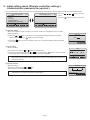
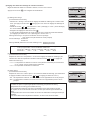
9. Initial setting menu (Remote controller settings)
<Administrator password is required.>
From the Main display, select Commissioning menu>Initial setting, and make the remote controller settings on the screen that appears.
(1) Main/Sub setting
When connecting two remote controllers, one of them needs to be designated as a sub controller.
[Button operation]
[1] When the or button is pressed, the currently selected setting will appear highlighted.
Select “Sub”, and press the button to save the change.
[2] Press the button to return to the Main menu screen. (This button always brings up the Main
menu screen.)
(2) Clock setting
[Button operation]
[1] Move the cursor with the or button to the desired item.
[2] Change the date and time with the or button, and press the button to save the change.
The change will be reflected on the clock display on the Main display.
(3) Display contrast
[Button operation]
Adjust LCD contrast with the or button.
The current level is indicated with a triangle.
Press the , , , button to move the
cursor.
Press the button to go to the next screen.
Initial setting menu 1/2
Main/Sub
Clock
Contrast
Display details
Administrator password
Cursor Page
Main menu:
Initial setting menu 2/2
Language selection
Cursor Page
Main menu:
Clock
Select:
Cursor
yyyy/ mm/ dd hh: mm
2 21 / 1 / 1
:
DarkLight
Contrast
Main menu:
Main/Sub
Main / Sub
Select:
Cursor
Note: Clock setting is necessary for setting the time, Fan speed timer, ON/OFF timer, Weekly timer,
Night-purge setting and Error history. Make sure to perform Clock setting when the product is
used for the first time.
Note: Adjust the contrast to improve viewing in different lighting conditions or installation locations.
This setting can not improve viewing from all directions.
Eng-11

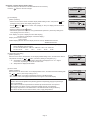
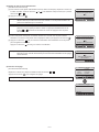
[1] Clock display
[Button operation]
• Select “Clock” from the remote controller display details setting screen, and press the button
(Change) to bring up the clock display setting screen.
• Use the through buttons to select “Yes” (display) or “No” (non-display) and its format for
the Main display.
• Save the settings with the button.
• Administrator password is required. See (5) Administrator password. (The factory settings are
“Yes” (display) and “24 h” format. )
Clock display: Yes (Time is displayed on the Main display.)
No (Time is not displayed on the Main display.)
Display format: 24-hour format
12-hour format
AM/PM display (Effective when the display format is 12-hour): AM/PM before the time
AM/PM after the time
[2] Temperature unit setting
[Button operation]
Move the cursor to the “Temperature” on the display details setting screen, and select the desired
temperature unit with the or button. (The factory setting is Centigrade (ºC).)
• “ ºC ”: Temperature is displayed Centigrade. Temperature is displayed in 0.5- or 1-degree
increments, depending on the model of indoor units.
• “ ºF ”: Temperature is displayed Fahrenheit.
[3] Sensor value
[Button operation]
Move the cursor to “Sensor value” on the display details screen, and select the desired setting with
the or button. (The factory setting is “No.”)
• Yes: Outdoor, return, and supply temperatures appear on the Main display.
• No: Outdoor, return, and supply temperatures do not appear on the Main display.
(4) Remote controller display details setting
Make the settings for the remote-controller-related items as necessary.
Press the button to save the changes.
Clock display
Cursor Cursor
Select:
Clock
12h disp.
AM/PM disp.
Yes No
Display details
Cursor Change
Select:
Clock
Temperature
Sensor value
No 24h
Yes / No
Display details
Cursor Change
Select:
Clock
Temperature
Sensor value
No 24h
Yes / No
Display details
Cursor Change
Select:
Clock
Temperature
Sensor value
No 24h
Yes / No
Note: Time display format will also be reflected on the timer and schedule setting display. The
time is displayed as shown below.
12-hour format: AM12:00 ~ AM1:00 ~ PM12:00 ~ PM 1:00 ~ PM11:59
24-hour format:
0:00 ~ 1:00 ~ 12:00 ~ 13:00 ~ 23:59
Note:
• Sensor value includes [Outdoor temperature], [Return temperature], [Supply temperature] or
[CO2 concentration].
• The outdoor and return temperatures are detected by the thermometer of the product.
• PZ-70 series CO2 sensor must be connected to display the [CO2 concentration].
• The supply temperature is calculated based on the standard heat-exchange efficiency.
• The values will differ from the actual outdoor, return, supply temperatures.
Eng-12

(5) Administrator password setting
[Button operation]
[1] To enter the current Administrator password (4 numerical digits), move the cursor to the digit you
want to change with the or button, and set each number (0 through 9) with the or
button.
[2] Press the button.
(6) Language selection
[Button operation]
Move the cursor to the language you desire with the through buttons.
Press the button to save the setting.
[3] If the password matches, a window to enter a new password will appear. Enter a new password in
the same way as explained above, and press the button.
[4] Press the button (OK) on the password change confirmation screen to save the change.
Press the button (Cancel) to cancel the change.
Administrator password
Enter administrator password
Select:
Cursor
Cursor
Select:
English
Deutsch
Italiano
Svenska
Français
Español
Português
Русский
Language selection 1/2
Cursor
Cursor
Select:
Nederlands
Language selection 2/2
Cursor
Administrator password
Enter administrator password
Change administrator password.
Select:
Cursor
Administrator password
Enter administrator password
Update administrator password?
Cancel OK
Note: The administrator password is required to make the settings for Commissioning menus.
Refer to the Instruction Book for the detailed information about how to make the settings for
these items.
Note: If you forget your administrator password, you can initialize the password to the default
password “9999” by pressing and holding the and buttons simultaneously for three
seconds on the administrator password setting screen.
Note: The initial administrator password is “9999”. Change the default password as necessary to
prevent unauthorized access. Have the password available for those who need it.
Note: Selectable language are different by each remote controller model.
Eng-13

HEAD OFFICE: TOKYO BLDG., 2-7-3, MARUNOUCHI, CHIYODA-KU, TOKYO 100-8310, JAPAN
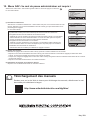
10. Service menu <Administrator password is required.>
Select “Service menu” from the Main menu > Commissioning and press the button.
The service menu will appear.
Note:
The following settings can be made from the Maintenance Information screen.
• Registering model names and serial numbers
Enter the model names and serial numbers of Lossnay unit. The information entered will
appear on the Error information screen. Model names can have up to 18 characters, and the
serial numbers can have up to 8 characters.
• Registering dealer information
Enter phone number of a dealer. The entered information will appear on the Error information
screen. Phone number can have up to 13 characters.
• Initializing maintenance information
Select the desired item to initialize the above settings.
(2) Function setting
Make the Lossnay units' function settings from the remote controller as necessary.
• Refer to the Lossnay unit Installation Manual for information about the factory settings of Lossnay units, function setting numbers, and
setting values.
• When changing the Lossnay units' function settings, record all the changes made to keep track of the settings.
• Refer to the Instruction Book for the remote controller.
(3) Initializing the settings of the remote controller
Refer to the Instruction Book for the remote controller.
Commissioning menu 1/2
Initial setting
Airflow
Auto bypass
External input
Service
Cursor Page
Main menu:
(1) Input maintenance Info.
Select “Input maintenance Info.” from the Service menu to bring up the Maintenance information
screen. Refer to the Lossnay unit Installation Manual for how to make the settings.
The service menu will appear.
Maintenance information
Model name input
Serial No. input
Dealer information input
Initialize maintenance info.
Cursor
Main menu:
Service menu
Cursor
Input maintenance info.
Function setting
Initializing
Main menu:
May 2021
Manual Download
Go to the website below to download manuals, select model name, then choose language.
http://www.mitsubishielectric.com/ldg/ibim/
Eng-14

Ce manuel d'installation décrit comment installer le contrôleur à distance Lossnay.
Assurez-vous de lire ce manuel d'installation avant de procéder à l'installation.
Le non-respect de ces instructions peut endommager l'équipement.
Pour des informations sur le câblage et l'installation des unités Lossnay, reportez-vous au manuel d'installation de l'unité Lossnay.
Après l’installation, remettez ce manuel aux utilisateurs.
1. Consignes de sécurité
• Lisez attentivement les consignes de sécurité ci-après avant de procéder à l’installation.
• Respectez scrupuleusement ces consignes pour assurer la sécurité.
AVERTISSEMENT Signale un risque de blessure grave, voire mortelle.
ATTENTION Signale un risque de blessure grave ou de dommage matériel.
• Après avoir lu ce manuel, remettez-le à l'utilisateur final pour qu'il puisse le consulter en cas de besoin.
• Conservez ce manuel pour pouvoir le consulter ultérieurement en cas de besoin. Ce manuel doit être fourni aux personnes chargées de réparer
ou de déplacer le contrôleur. Assurez-vous que le manuel est bien remis à tout futur utilisateur.
AVERTISSEMENT
ATTENTION
Précautions générales
N'utilisez par les commutateurs/touches ou d'autres parties
électriques avec les mains mouillées afin de prévenir tout risque
d'électrocution, de dysfonctionnement, de fumée ou d'incendie.
Ne lavez pas le contrôleur avec de l’eau ou tout autre liquide
afin de prévenir tout risque de court-circuit, de fuite électrique,
d’électrocution, de dysfonctionnement, de fumée ou d’incendie.
N'installez pas l'unité en un endroit où se trouvent de grandes quantités d'huile, de
vapeur, de solvants organiques ou de gaz corrosifs tels du gaz sulfurique ou encore
là où sont fréquemment utilisés des aérosols ou des solutions acides/alcalines. Ces
substances peuvent affecter les performances de l'unité ou provoquer la corrosion de
certains de ses composants, ce qui peut donner lieu à des défauts de fonctionnement,
des dégagements de fumée ou même une électrocution ou un incendie.
Pour éviter tout risque de blessure ou d’électrocution, éteignez le
contrôleur et couvrez-le avant de pulvériser un quelconque produit
chimique dans l’environnement de celui-ci.
Pour éviter tout risque de blessure ou d'électrocution, éteignez la
télécommande et coupez l'alimentation électrique avant de la nettoyer, de
l'examiner, ou avant toute opération d'entretien de celle-ci.
Installez correctement toutes les protections requises pour protéger le
contrôleur contre l’humidité et la poussière. L'accumulation de poussière et
d'eau peut provoquer des électrocutions, de la fumée ou un incendie.
Pour prévenir tout risque de blessure, éloignez les enfants lors de
l’installation, l’inspection ou la réparation du contrôleur.
Tous les travaux électriques doivent être effectués par du personnel qualifié.
Pour prévenir tout risque d’incendie ou d’explosion, ne placez pas de matériaux inflammables
et ne pulvérisez pas de substances inflammables dans l’environnement du contrôleur.
Pour prévenir tout risque d’endommagement du contrôleur, ne pulvérisez pas
d’insecticide ou tout autre aérosol inflammable directement sur le contrôleur.
Ne touchez pas l'écran ou les boutons avec un objet pointu ou tranchant
afin de prévenir tout risque d'électrocution ou de dysfonctionnement.
Évitez le contact avec les bords tranchants de certaines parties afin
de prévenir tout risque de blessure et d'électrocution.
N'exercez pas une force excessive sur les parties en verre pour
éviter qu'elles se brisent et provoquent des blessures.
Pour prévenir tout risque de blessure, portez un équipement de
protection lors de toute intervention sur le contrôleur.
Pour distribution aux revendeurs et aux sous-traitants
Contrôleur à distance Lossnay
PZ-62DR-E
Manuel d’installation
Français
─ 1 ─

Précautions pendant l’installation
Précautions pendant le câblage
Précautions pour le déplacement ou la réparation la télécommande
Précautions supplémentaires
AVERTISSEMENT
AVERTISSEMENT
AVERTISSEMENT
ATTENTION
ATTENTION
ATTENTION
Mettez les matériels d’emballage au rebut conformément à la réglementation. Les
enfants risquent de s’étouffer avec les sachets en plastique.
Fixez correctement les câbles en place et laissez assez de mou aux câbles pour
ne pas exercer de contrainte sur les bornes. Des câbles mal connectés peuvent se
casser, surchauffer, et provoquer de la fumée ou un incendie.
Ce contrôleur est exclusivement destiné à être utilisé avec l’unité Lossnay
de Mitsubishi Electric. L’utilisation de ce contrôleur avec d’autres systèmes
ou à d’autres fins peut entraîner des dysfonctionnements.
Ne serrez pas trop les vis pour éviter d’endommager le contrôleur.
N’installez pas le contrôleur dans un endroit où peut se produire une
fuite de gaz inflammable. Si du gaz inflammable s’accumule autour du
contrôleur, il peut s’enflammer et provoquer un incendie ou une explosion.
Pour prévenir tout risque de dommage au contrôleur, de dysfonctionnement, de dégagement
de fumée ou d’incendie, ne branchez pas le câble d’alimentation au bornier des signaux.
Pour prévenir tout dommage au contrôleur, utilisez des outils
appropriés pour son installation, son inspection ou sa réparation. Pour éviter des dysfonctionnements, ne retirez pas le film de
protection ou le circuit imprimé du boîtier.
Pour prévenir tout dysfonctionnement, n’attachez pas les câbles d’alimentation et de
signaux ensemble et faites-les passer dans des chemins de câbles différents.
N’utilisez pas de benzène, de diluant, d’éthanol, d’acide hypochloreux ou
d’abrasif chimique pour nettoyer le contrôleur afin d’éviter de le décolorer.
Pour nettoyer le contrôleur, essuyez-le avec un chiffon doux imbibé d'un
mélange d'eau et d'un détergent doux, rincez les restes de détergent avec
un chiffon humide, puis essuyez l'eau avec un chiffon sec.
Pour éviter d’endommager le boîtier du contrôleur, ne forcez pas pour faire
tourner le tournevis lorsque sa pointe est insérée dans la fente.
Pour prévenir tout risque de blessure et d’électrocution, coupez
l’alimentation générale avant d’effectuer un travail électrique.
Prenez des dispositions appropriées contre les interférences électromagnétiques
lorsque le contrôleur Lossnay est installé dans des hôpitaux ou à proximité
d’équipements de radiocommunication. Les onduleurs, ainsi que les équipements
médicaux à haute fréquence ou de communication sans fil et les générateurs
d'énergie peuvent être la cause de dysfonctionnements du contrôleur Lossnay. Le
contrôleur Lossnay peut également affecter le bon fonctionnement de ces types
d’équipement en créant du bruit électrique.
Utilisez un tournevis à tête plate avec une lame de 4-7 mm (5/32-
9/32 pouce). L’utilisation d’un tournevis avec une lame plus étroite
ou plus large peut endommager le boîtier du contrôleur.
Prenez des mesures de sécurité appropriées contre les tremblements de
terre pour éviter que le contrôleur provoque des blessures.
Tous les travaux électriques doivent être effectués par un électricien qualifié
conformément à la réglementation et aux normes locales et en suivant les
instructions décrites dans le Manuel d’installation. Une capacité insuffisante
du circuit d’alimentation ou une installation incorrecte peut entraîner un
dysfonctionnement, un choc électrique, de la fumée ou un incendie.
Pour prévenir tout risque de blessure, installez le contrôleur sur une
surface plane suffisamment solide pour supporter son poids.
Pour prévenir tout risque de fuite électrique, de surchauffe, de dégagement
de fumée ou d’incendie, utilisez des câbles de section appropriée pour le
courant nominal spécifié.
Pour prévenir tout risque de court-circuit, de fuite électrique, d’électrocution,
de dysfonctionnement, de fumée ou d’incendie, n’installez pas le contrôleur
en un endroit exposé à l’eau ou à la condensation.
Pour réduire les risques d’électrocution, de court-circuit ou de
dysfonctionnement, retirez toutes les chutes de fil et de gaine du bornier.
Seul un personnel qualifié doit être autorisé à réparer le contrôleur ou à le changer de place. Ne démontez pas
ou ne modifiez pas le contrôleur.
Une installation ou une réparation non conforme peut entraîner des blessures, une électrocution ou un incendie.
Le contrôleur doit être installé par du personnel qualifié en suivant les instructions
décrites dans le Manuel d’installation.
Une installation incorrecte peut être la cause d’une électrocution ou d’un incendie.
Pour prévenir tout risque de court-circuit, de fuite électrique, d’électrocution ou de
dysfonctionnement, ne laissez pas les câbles entrer en contact avec les bords vifs du contrôleur.
Quand vous fixez le couvercle et le boîtier supérieur au boîtier
inférieur, poussez-les jusqu’à ce qu’ils s’enclenchent en place. S’ils
ne sont pas correctement verrouillés en place, ils peuvent tomber,
et provoquer des blessures, des dommages au contrôleur, ou des
dysfonctionnements.
Pour prévenir tout risque d’électrocution, de dysfonctionnement ou
d’incendie, bouchez l’espace entre les câbles et les trous d’accès des
câbles avec du mastic.
Pour prévenir tout risque de court-circuit, d'électrocution, d'incendie ou de
dysfonctionnement, ne touchez pas le circuit imprimé avec des outils ou
vos mains et ne laissez pas la poussière s'accumuler dessus.
─ 2 ─

N’utilisez pas de bornes à sertir pour raccorder les câbles au bornier.
Ce type de borne risque d’entrer en contact avec le circuit imprimé et de
provoquer des dysfonctionnements, voire même d’endommager le
cache du contrôleur.
Protégez le contrôleur contre l’électricité statique pour éviter de
l’endommager.
N’installez pas le contrôleur sur la porte du panneau de commande.
Des vibrations ou des chocs subis par le contrôleur pourraient
l’endommager ou le faire tomber.
Ne l’installez pas dans un endroit très humide comme à l’intérieur
d’une salle de douche, etc. La plage d’humidité relative doit être de
30 % à 90 % sans condensation.
Pour éviter une rupture du câble et des dysfonctionnements, ne
laissez pas le boîtier supérieur du contrôleur pendre au bout du
câble.
Ne percez pas de trous dans le cache pour éviter d’endommager
le contrôleur.
Maintenez les câbles en place avec des serre-fils pour éviter qu’une
force inappropriée ne soit appliquée au bornier et provoque des
ruptures de câbles.
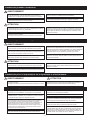
2. Nomenclature des composants et pièces fournies
Les pièces suivantes sont incluses dans l’emballage.
Nom des pièces Qté Apparence
Contrôleur à distance (face avant) 1 Figure de droite *1
Contrôleur à distance (boîtier supérieur) 1Figure de droite *2
Contrôleur à distance (boîtier inférieur) 1Figure de droite *3
Vis cruciformes à tête ronde M4×30 2
Vis à bois 4,1×16
(pour une installation directe au mur) 2
Manuel simplié (le présent manuel) 1
*4 La face avant (*1) est déjà installée sur le boîtier supérieur (*2) lors de
l’expédition de l’usine.
*5 Le câble du contrôleur à distance n’est pas inclus.
Boîtier inférieur *3
Face avant *1 Boîtier supérieur *2
*4
─ 3 ─

3. Pièces à fournir sur site/Outils requis
4. Choix d’un site d’installation
(1) Pièces à fournir sur site
Les pièces suivantes sont des pièces à fournir sur le site.
Nom des pièces Qté Remarques
Boîtier de connexion double 1
Non requis pour une installation directe au murConduit métallique à paroi mince Nécessaire
Écrou de blocage et douille Nécessaire
Cache de câble Nécessaire Requis pour faire passer le câble du contrôleur à
distance le long d’un mur
Mastic Raisonnable
Boulon d’ancrage à expansion Nécessaire
Câble du contrôleur à distance
(Utilisez un câble gainé à 2 conducteurs de 0,3 mm² (AWG22).) Nécessaire
(2) Outils à fournir sur site
● Tournevis plat (largeur : 4-7 mm (5/32-9/32 pouce))
● Couteau ou pince
● Outils divers
Ce contrôleur à distance est prévu pour une installation murale. Il peut être installé dans le boîtier de connexion ou directement sur le mur.
Lorsque vous effectuez une installation directement sur un mur, les fils peuvent être acheminés par l’arrière ou le dessus du contrôleur à
distance.
(1) Choix d’un site d’installation
Pour prévenir tout risque de blessure, installez le contrôleur sur une surface plane suffisamment solide pour supporter son poids.
Important
(2) Espace d’installation
Que le contrôleur à distance soit installé dans le boîtier de connexion ou directement sur
le mur, laissez un espace autour du contrôleur comme indiqué sur la figure de droite. Il
ne sera pas facile d’enlever le contrôleur à distance si l’espace est insuffisant.
Laissez également un espace adéquat devant le contrôleur à distance pour faciliter son
utilisation.
30
(1-3/16)
30
(1-3/16)
30 (1-3/16)
120 (4-3/4)
120 (4-3/4)
120 (4-3/4)
Dimensions externes du
contrôleur à distance
Espace
minimum
requis autour
du contrôleur à
distance
unité : mm (po)
Pour prévenir tout risque de court-circuit, de fuite électrique,
d’électrocution, de dysfonctionnement, de fumée ou d’incendie, n’installez
pas le contrôleur en un endroit exposé à l’eau ou à la condensation.
Pour prévenir toute déformation et dysfonctionnement, n’installez par la
télécommande en un endroit directement exposé au soleil ou là où la température
peut dépasser 40°C (104°F) ou chuter au-dessous de 0°C (32°F).
Ne l’installez pas dans un endroit très humide comme à l’intérieur
d’une salle de douche, etc. La plage d’humidité relative doit être de
30 % à 90 % sans condensation.
Pour réduire le risque de dysfonctionnement et d’endommagement
du contrôleur, évitez d’installer le contrôleur à distance sur une
surface électriquement conductrice, telle qu’une tôle non peinte.
─ 4 ─

5. Travaux d’installation/de câblage
(1) Travaux d’installation
Le contrôleur peut être installé dans le boîtier de connexion ou directement sur le
mur. Effectuez l’installation adéquatement selon la méthode.
1 Percez un trou dans le mur.
■ Installation avec un boîtier de connexion
● Percez un trou dans le mur et installez le boîtier de connexion sur le
mur.
● Raccordez le boîtier de connexion au tuyau de conduit.
■ Installation directe au mur
● Percez un trou dans le mur et faites-y passer le câble.
2 Bouchez le trou d’accès du câble avec du mastic.
■ Installation avec un boîtier de connexion
● Bouchez le trou d’accès du câble du contrôleur à distance à la jointure
entre le boîtier de connexion et le tuyau de conduit avec du mastic.
Pour prévenir tout risque d’électrocution, de dysfonctionnement
ou d’incendie, bouchez l’espace entre les câbles et les trous
d’accès des câbles avec du mastic.
3 Préparez le boîtier inférieur du contrôleur à distance.
Face avant et boîtier supérieur Boîtier inférieur
4 Connectez le câble du contrôleur à distance au bornier sur le boîtier inférieur.
10 (13/32)
6 (1/4)
Faites passer le câble.
Avant Arrière Connectez le
câble de façon
que la gaine ne
soit pas pincée.
Connectez le câble
(non polarisé).
Le fil à 2 conducteurs ne doit
pas être visible à l’arrière.
unité : mm (po)
Gaine
Enfilez la partie gainée du
câble vers l’avant.
Dénudez 6 mm de la gaine du câble du contrôleur à distance comme indiqué sur la figure ci-dessous, et faites passer le câble
par l’arrière du boîtier inférieur. Enfilez le câble vers l’avant du boîtier inférieur de sorte que la partie dénudée du câble ne soit
pas visible derrière le boîtier inférieur. Connectez le câble du contrôleur à distance au bornier sur le boîtier inférieur.
■ Installation directe au mur
● Bouchez le trou d’acheminement du câble avec du mastic.
Pour réduire les risques d’électrocution, de court-circuit ou de
dysfonctionnement, retirez toutes les chutes de fil et de gaine du
bornier.
Important
Câble du contrôleur
à distance
Bouchez l’espace avec du mastic.
Faites passer le câble derrière
le contrôleur à distance.
N’utilisez pas de bornes à sertir pour raccorder les câbles au bornier.
Ce type de borne risque d’entrer en contact avec le circuit imprimé et
de provoquer des dysfonctionnements, voire même d’endommager le
cache du contrôleur.
Câble du contrôleur à distance
Bouchez l’espace
avec du mastic.
Boîtier de connexion
Douille
Tuyau de conduit
Écrou de blocage
Mur
─ 5 ─

5 Installez le boîtier inférieur.
■ Installation avec un boîtier de connexion
● Fixez au moins deux coins du boîtier de connexion avec des vis.
■ Installation directe au mur
● Faites passer le câble dans la rainure.
● Fixez au moins deux coins du contrôleur à distance avec des vis.
● Veillez à fixer les coins supérieur gauche et inférieur droit du contrôleur à distance (vue de face) pour l’empêcher de se
soulever. (Utilisez un boulon d’ancrage à expansion, etc.)
■ Installation directe au mur■ Installation avec un boîtier de connexion
Bouchez le trou d’accès
du câble avec du mastic.
Voir 2.
Câble du contrôleur
à distance
Voir 4.
Faites passer le câble
dans la rainure.
Vis cruciformes à
tête ronde
Vis à
bois
Boîtier de connexion double
Câble du contrôleur
à distance
Voir 4.
Important
Important
6 Découpez le trou d’accès du câble.
■ Installation directe au mur (en faisant passer le câble le long du mur)
● Découpez la partie peu épaisse sur le boîtier (indiquée par la zone grisée sur la figure
de droite) avec un couteau ou une pince.
● Faites passer le câble de la rainure à l’arrière du boîtier inférieur à travers ce trou
d’accès.
7 Acheminez le fil jusqu’au boîtier supérieur.
Connectez le connecteur du boîtier inférieur au connecteur du boîtier supérieur.
Connectez
correctement les
connecteurs.
Ne serrez pas trop les vis pour éviter d’endommager le
contrôleur.
Ne percez pas de trous dans le cache pour éviter
d’endommager le contrôleur.
Pour éviter des dysfonctionnements, ne retirez pas le film de
protection ou le circuit imprimé du boîtier.
Pour éviter une rupture du câble et des dysfonctionnements,
ne laissez pas le boîtier supérieur du contrôleur pendre au
bout du câble.
─ 6 ─
La page est en cours de chargement...
La page est en cours de chargement...
La page est en cours de chargement...
La page est en cours de chargement...
La page est en cours de chargement...
La page est en cours de chargement...
La page est en cours de chargement...
La page est en cours de chargement...
-
 1
1
-
 2
2
-
 3
3
-
 4
4
-
 5
5
-
 6
6
-
 7
7
-
 8
8
-
 9
9
-
 10
10
-
 11
11
-
 12
12
-
 13
13
-
 14
14
-
 15
15
-
 16
16
-
 17
17
-
 18
18
-
 19
19
-
 20
20
-
 21
21
-
 22
22
-
 23
23
-
 24
24
-
 25
25
-
 26
26
-
 27
27
-
 28
28


Mitsubishi Electric PZ-62DR-E Manuel utilisateur
- Taper
- Manuel utilisateur
dans d''autres langues
Documents connexes
-
Mitsubishi Electric PAC-YT53CRAU Guide d'installation
-
-
-
Mitsubishi Electric PKA-A30KA7 Le manuel du propriétaire
-
Mitsubishi Electric Electric Air Distribution Grille Indoor Cassette Le manuel du propriétaire
-
Mitsubishi Electric PLA-A30EA7 Le manuel du propriétaire
-
