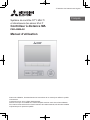
Mitsubishi Electric PAR-40MAAU Le manuel du propriétaire
- Taper
- Le manuel du propriétaire

English
Français
Español
<ORIGINAL>
Prior to use, thoroughly read the instructions in this manual to use the product correctly.
Retain for future reference.
Make sure that this CD-ROM and the simple Manual are passed on to any future users.
To ensure safety and proper operation of the remote controller, the remote controller should
only be installed by qualified personnel.
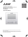
CITY MULTI Control System
and M-series and P-series Air Conditioners
MA Remote Controller
PAR-40MAAU
Instruction Book


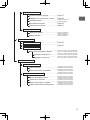
Safety precautions ................................................4
Controller components .........................................6
Controller interface ..............................................................6
Display .................................................................................8
Menu structure and icons ...................................10
Menu structure ................................................................... 10
Icon explanations ............................................................... 13
Basic operations .................................................14
Power ON/OFF ..................................................................14
Operation mode, temperature, fan speed,
and HOLD settings ............................................................15
Navigating through the menu .............................20
Main menu list .................................................................... 20
Restrictions for the sub remote controller ..........................21
Navigating through the Main menu .................................... 22
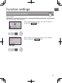
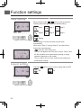
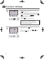
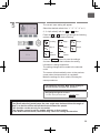
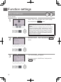
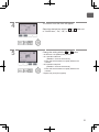
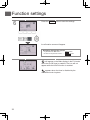
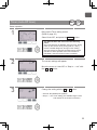
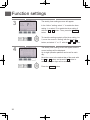
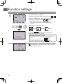
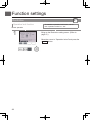
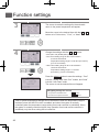
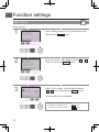
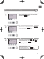
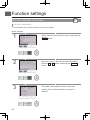
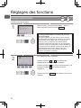
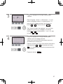
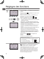
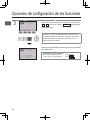
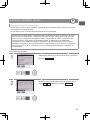
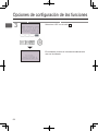
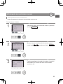
Function settings ................................................23
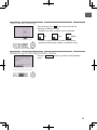
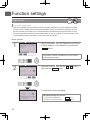
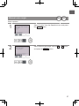
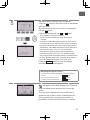
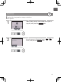
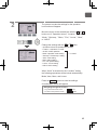
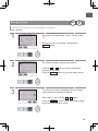
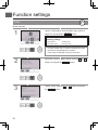
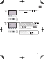
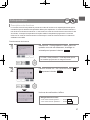
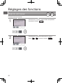
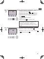
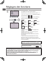
Vane•Louver•Vent. (Lossnay) ............................................23
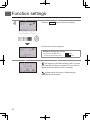
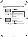
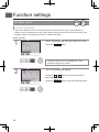
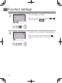
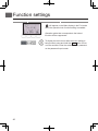
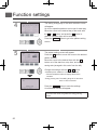
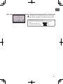
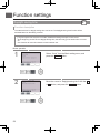
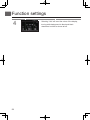
High power ......................................................................... 26
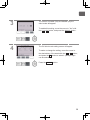
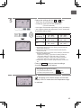
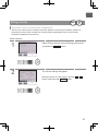
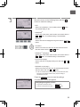
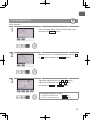
Manual vane angle ............................................................27
Timer (On/Off timer) ...........................................................30
Timer (Auto-Off timer) ........................................................33
Weekly timer ......................................................................35
OU silent mode ..................................................................38
Restriction ..........................................................................41
Energy saving ....................................................................47
Clock ..................................................................................52
Daylight saving time ........................................................... 54
Main display ....................................................................... 56
Black and white inversion setting .......................................57
Contrast•Brightness ...........................................................59
Language selection ............................................................ 60
Initialize remote controller .................................................. 62
Remote controller information ............................................64
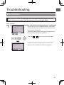
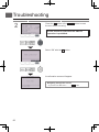
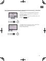
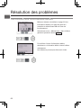
Troubleshooting ..................................................65
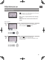
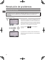
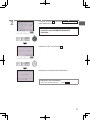
Error information ................................................................65
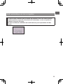
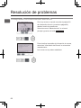
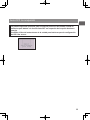
No occupancy Auto-OFF ...................................................68
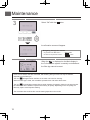
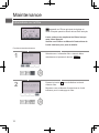
Maintenance .......................................................69
Filter information ................................................................69
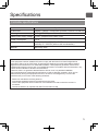
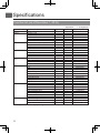
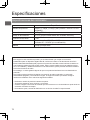
Specifications .....................................................71
Controller specifications ..................................................... 71
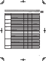
Function list (as of December 1, 2018) .............................. 72
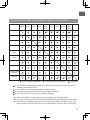
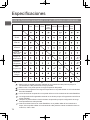
List of functions that can/cannot be used in combination ..73
Contents

4
Safety precautions
•
Thoroughly read the following safety precautions before using the unit.
•
Observe these precautions carefully to ensure safety.
WARNING
Indicates a risk of death or serious injury.
CAUTION
Indicates a risk of serious injury or structural damage.
•
After reading this manual, pass it on to the end user to retain for future reference.
•
Keep this manual for future reference and refer to it as necessary. This manual should be made available
to those who repair or relocate the controller. Make sure that the manual is passed on to any future
users.
General precautions
WARNING
Do not install the unit in a place where large
amounts of oil, steam, organic solvents, or corrosive
gases, such as sulfuric gas, are present or where
acidic/alkaline solutions or sprays are used
frequently. These substances can compromise the
performance of the unit or cause certain components
of the unit to corrode, which can result in electric
shock, malfunctions, smoke, or fire.
To reduce the risk of shorting, current leakage,
electric shock, malfunctions, smoke, or fire, do not
wash the controller with water or any other liquid.
To reduce the risk of electric shock, malfunctions,
smoke or fire, do not operate the switches/buttons or
touch other electrical parts with wet hands.
When disinfecting the unit using alcohol, ventilate
the room adequately. The fumes of the alcohol
around the unit may cause a fire or explosion when
the unit is turned on.
To reduce the risk of injury or electric shock, before
spraying a chemical around the controller, stop the
operation and cover the controller.
To reduce the risk of injury or electric shock, stop the
operation and switch off the power supply before
cleaning, maintaining, or inspecting the controller.
If any abnormality (e.g., burning smell) is noticed,
stop the operation, turn off the power switch, and
consult your dealer. Continued use of the product
may result in electric shock, malfunctions, or fire.
Properly install all required covers to keep moisture
and dust out of the controller. Dust accumulation and
water can cause electric shock, smoke, or fire.
CAUTION
To reduce the risk of fire or explosion, do not place
flammable materials or use flammable sprays
around the controller.
To reduce the risk of damage to the controller, do not
directly spray insecticide or other flammable sprays
on the controller.
To reduce the risk of environmental pollution, consult
an authorized agency for proper disposal of remote
controller.
To reduce the risk of electric shock or malfunctions,
do not touch the touch panel, switches, or buttons
with a pointy or sharp object.

5
To reduce the risk of injury and electric shock, avoid
contact with sharp edges of certain parts.
To avoid injury from broken glass, do not apply
excessive force on the glass parts.
To reduce the risk of injury, wear protective gear
when working on the controller.
Precautions for moving or repairing the controller
WARNING CAUTION
The controller should be repaired or moved only by
qualified personnel. Do not disassemble or modify
the controller.
Improper installation or repair may cause injury,
electric shock, or fire.
To reduce the risk of shorting, electric shock, fire, or
malfunction, do not touch the circuit board with tools
or with your hands, and do not allow dust to
accumulate on the circuit board.
Additional precautions
To avoid damage to the controller, use appropriate
tools to install, inspect, or repair the controller.
This controller is designed for exclusive use with the
Building Management System by Mitsubishi Electric.
The use of this controller for with other systems or
for other purposes may cause malfunctions.
This appliance is not intended for use by persons
(including children) with reduced physical, sensory or
mental capabilities, or lack of experience and
knowledge, unless they have been given supervision
or instruction concerning use of the appliance by a
person responsible for their safety.
Children should be supervised to ensure that they do
not play with the appliance.
To avoid discoloration, do not use benzene, thinner,
or chemical rag to clean the controller. To clean the
controller, wipe with a soft cloth soaked in mild
detergent that is diluted with an appropriate amount
of water, and wipe down with a wet cloth followed by
a dry cloth. Do not use the detergent straight.
To avoid damage to the controller, provide protection
against static electricity.
This appliance is intended to be used by expert or
trained users in shops, in light industry and on farms,
or for commercial use by lay persons.
If the supply cord is damaged, it must be replaced by
the manufacturer, its service agent or similarly
qualified persons in order to avoid a hazard.

6
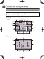
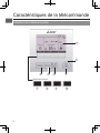
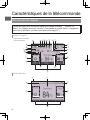
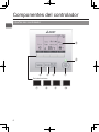
Controller components
Controller interface
⑤
⑥
①②③④
⑦ ⑧
⑨
⑩
Function buttons

7
①
ON/OFF
button
Press to turn ON/OFF the indoor unit.
②
SELECT/HOLD
button
Press to save the setting.
When the Main menu is displayed,
pressing this button will enable/disable the
HOLD function.
③
RETURN
button
Press to return to the previous screen.
④
MENU
button Page 22
Press to bring up the Main menu.
⑤
Backlit LCD
Operation settings will appear.
When the backlight is off, pressing any
button turns the backlight on and it will stay
lit for a certain period of time depending on
the screen.
When the backlight is off, pressing any
button turns the backlight on and does
not perform its function. (except for the
ON/OFF
button)
⑥
ON/OFF lamp
This lamp lights up in green while the unit
is in operation. It blinks while the remote
controller is starting up or when there is an
error.
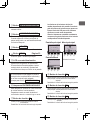
⑦
Function button
F1
Main display: Press to change the
operation mode.
Menu screen: The button function varies
with the screen.
The functions of the function buttons
change depending on the screen. Refer
to the button function guide that
appears at the bottom of the LCD for
the functions they serve on a given
screen.
When the system is centrally
controlled, the button function guide
that corresponds to the locked button
will not appear.
Main display Main menu
Cursor Page
Menu screen
⑧
Function button
F2
Main display:
Press to decrease temperature.
Main menu: Press to move the cursor left.
Menu screen: The button function varies
with the screen.
⑨
Function button
F3
Main display:
Press to increase temperature.
Main menu:
Press to move the cursor right.
Menu screen: The button function varies
with the screen.
⑩
Function button
F4
Main display:
Press to change the fan speed.
Menu screen: The button function varies
with the screen.
Function guide
⑦ ⑧ ⑨ ⑩ ⑦ ⑧ ⑨ ⑩
⑦ ⑧ ⑨ ⑩

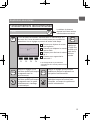
8
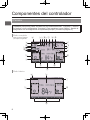
Controller components
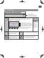
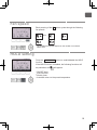
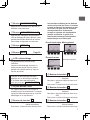
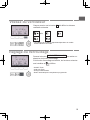
Display
The main display can be displayed in two different modes: “Full” and “Basic.”
The factory setting is “Full.” To switch to the “Basic” mode, change the setting
on the Main display setting. (Refer to page 56.)
Full mode
Basic mode
2
5
k
3
4
i
l
j
a
bn cde f g h
0
8
7
9
6
m
1
* All icons are displayed for
explanation.
1
m
n 2
3
4
5

9
①
Operation mode Page 15
②
Preset temperature Page 17
③
Clock
See the Installation Manual.
④
Fan speed Page 19
⑤
Button function guide
Functions of the corresponding buttons appear
here.
⑥
Appears when the ON/OFF operation is
centrally controlled.
⑦
Appears when the operation mode is centrally
controlled.
⑧
Appears when the preset temperature is
centrally controlled.
⑨
Appears when the filter reset function is
centrally controlled.
⑩
Page 69
Indicates when filter needs maintenance.
⑪
Room temperature
See the Installation Manual.
⑫
Page 44
Appears when the buttons are locked.
⑬
Page 30, 33
Appears when the On/Off timer (Page 30) or
Auto-off timer (Page 33) function is enabled.
appears when the timer is disabled by the
centralized control system.
appears when the HOLD function is
enabled.
⑭
Page 35
Appears when the Weekly timer is enabled.
⑮
Page 49
Appears while the units are operated in the
energy-save mode. (Will not appear on some
models of indoor units)
⑯
Page 38
Appears while the outdoor units are operated in
the silent mode.
⑰
Appears when the built-in thermistor on the
remote controller is activated to monitor the
room temperature (
a
).
appears when the thermistor on the indoor
unit is activated to monitor the room
temperature.
⑱
Page 24
Indicates the vane setting.
⑲
Page 24
Indicates the louver setting.
⑳
Page 25
Indicates the ventilation setting.
㉑
Page 41
Appears when the preset temperature range is
restricted.
㉒
Appears when an energy-saving operation is
performed using a “3D i-See sensor” function.
㉓
Centrally controlled
Appears for a certain period of time when a
centrally-controlled item is operated.
㉔
Error display
An error code appears during the error.
* When an error code is displayed on the main
display, an error is occurring but the indoor unit
can keep its operation. Check the error code,
and consult your dealer.
Most settings (except ON/OFF, mode, fan
speed, temperature) can be made from
the Main menu. (Refer to Page 22.)

10
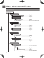
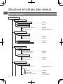
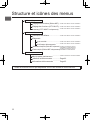
Menu structure and icons
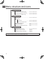
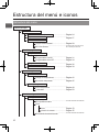
Menu structure
Main menu
Vane•Louver•Vent. (Lossnay)
............................
Page 23
High power
.......................................
Page 26
Comfort
Manual vane angle
.............................
Page 27
3D i-See sensor
...................................
Refer to the indoor unit Instruction Book.
Timer
On/Off timer
........................................
Page 30
Auto-Off timer
.....................................
Page 33
Weekly timer
.......................................
Page 35
OU silent mode
.......................................
Page 38
Restriction
Temp. range
.........................................
Page 41
Operation locked
..................................
Page 44
Energy saving
Auto return
...........................................
Page 47
Schedule
.............................................
Page 49
Basic setting
Main/Sub
.............................................
Refer to the Installation Manual.
Clock
Clock
.........................................
Page 52
Daylight saving time
...................
Page 54
Administrator password
........................
Refer to the Installation Manual.
Operation
Timer menu
Energy saving
Initial setting menu

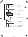
11
Display setting
Main display
.........................................
Page 56
Black and white inversion setting
..........
Page 57
Display details
......................................
Refer to the Installation Manual.
Contrast•Brightness
............................
Page 59
Language selection
..............................
Page 60
Operation setting
Auto mode
...........................................
Refer to the Installation Manual.
Setback mode
......................................
Refer to the Installation Manual.
Error information
.......................................
Page 65
Filter information
.......................................
Page 69
Cleaning
Auto descending panel
.......................
Refer to the Instructions Manual that
came with the automatic elevating panel.
Descending operation
................
Refer to the Instructions Manual that
came with the automatic elevating panel.
Descending adjustment
..............
Refer to the Instructions Manual that
came with the automatic elevating panel.
Test run menu
Test run
...............................................
Refer to the indoor unit Installation
Manual.
Drain pump test run
............................
Refer to the indoor unit Installation
Manual.
Maintenance information
..................................
Refer to the indoor unit Installation
Manual.
Model name input
...............................
Refer to the indoor unit Installation
Manual.
Serial No. input
...................................
Refer to the indoor unit Installation
Manual.
Dealer information input
.....................
Refer to the indoor unit Installation
Manual.
Initialize maintenance info.
.................
Refer to the indoor unit Installation
Manual.
Maintenance menu
Service menu

12
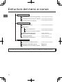
Menu structure and icons
Settings menu
Function setting (M/P-series)
..............
Refer to the Installation Manual.
Function setting (CITY MULTI)
...........
Refer to the Installation Manual.
Lossnay (CITY MULTI only)
................
Refer to the Installation Manual.
Check menu
Error history
........................................
Refer to the Installation Manual.
Diagnosis
Self check
..................................
Refer to the Installation Manual.
Remote controller check
.............
Refer to the Installation Manual.
Smooth maintenance
(
M/P-series
only)
.......................
Refer to the indoor unit Installation
Manual.
Request code (M/P-series
only
)
..........
Refer to the indoor unit Installation
Manual.
Other menu
Maintenance password
.......................
Refer to the Installation Manual.
Initialize remote controller
..................
Page 62
Remote controller information
............
Page 64
Not all functions are available on all models of indoor units.

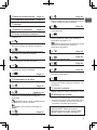
13
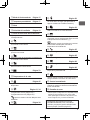
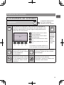
Icon explanations
Controller operation
Timer
The administrator or maintenance user password must be entered
on the password input screen to change settings. There is no
settings that can skip this process.
Main
F1
: Press to move the cursor left.
F2
: Press to move the cursor right.
F3
: Press to decrease the value by 1.
F4
: Press to increase the value by 1.
*
Changes cannot be made unless the
correct password is entered.
Indicates
settings that
can be
made only
from the
main remote
controller.
ON
Indicates settings that can
be changed only while the
units are in operation.
OFF
Indicates settings that can be changed
only while the units are not in operation.
Indicates settings that can
be changed only while the
units are operated in the
Cool, Heat, or Auto mode.
Indicates functions that are not available
when the buttons are locked or the
system is centrally controlled.
The table below
summarizes the square
icons used in this manual.
F4F3F2F1

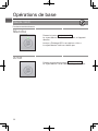
14
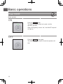
Basic operations
Power ON/OFF
Button operation
ON
Press the
ON/OFF
button.
The ON/OFF lamp will light up in green, and the
operation will start.
When “LED lighting” is set to “No,” the ON/OFF lamp will
not light up.
OFF
Press the
ON/OFF
button again.
The ON/OFF lamp will come off, and the operation will
stop.

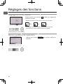
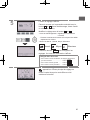
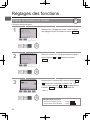
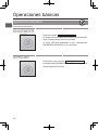
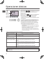
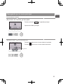
15
Operation mode, temperature, fan speed,
and HOLD settings
Button operation
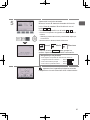
Operation mode
Each pressing of the
F1
button cycles through the following
operation modes.
Select the desired operation mode.
Cool Drying Fan
Auto Heat Setback
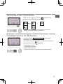
•
Operation modes that are not available to the connected indoor unit
models will not appear on the display.
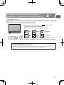
What the blinking mode icon means
The mode icon will blink when other indoor units in the same refrigerant system (connected to the same
outdoor unit) are already operated in a different mode. In this case, the rest of the unit in the same
group can only be operated in the same mode.
ON

16
Basic operations
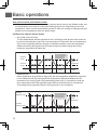
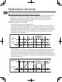
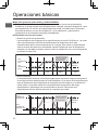
Auto (dual set point) and Setback modes:
When the operation mode is set to the Auto (dual set point) mode or the Setback mode, two
set temperatures (one each for cooling and heating) can be set. Depending on the room
temperature, indoor unit will automatically operate in either the cooling or heating mode and
keep the room temperature within the preset range.
■
Differences between the two modes
•
Auto (dual set point) mode
The set temperatures that are specified for the Cool/Drying mode and the Heat mode will
be used to automatically control the room temperature to stay within the set temperatures.
This mode is especially effective during the in-between seasons, when the temperature
difference between the highest and the lowest is large and both heating and cooling
modes are used within the same day.
•
Setback mode
Room temperature is controlled to stay within the set temperature range that is specified
for the Setback mode. By leaving sufficient temperature differential between the set
temperature for cooling (upper limit) and heating (lower limit), it is possible to keep the
room temperature within the specified range without overworking the air conditioners.
This setting will be especially effective during periods of non-occupancy.
Set temp.
(Cool)
Set temp.
(Heat)
Operation pattern during Auto (dual set point) mode
Heat Cool
The room temperature
changes corresponding
to the change in the
outside temperature.
Heat
Room
temperature
Cool
Set temp.
(Setback_Cool)
Set temp.
(Setback_Heat)
Operation pattern during Setback mode
Heat Cool
The room temperature
changes corresponding
to the change in the
outside temperature.
Heat
Room
temperature
Cool

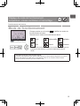
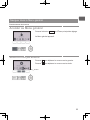
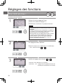
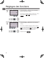
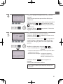
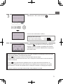
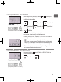
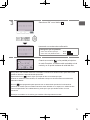
17
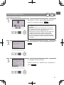
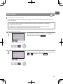
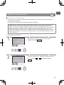
Preset temperature
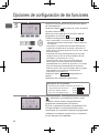
<Cool, Drying, Heat, and Auto (single set point)>
Press the
F2
button to decrease the preset
temperature, and press the
F3
button to increase.
•
Refer to the table on page 18 for the settable
temperature range for different operation modes.
•
Preset temperature range cannot be set for Fan/
Ventilation operation.
•
Preset temperature will be displayed either in Centigrade
in 0.5- or 1-degree increments, or in Fahrenheit,
depending on the indoor unit model and the display mode
setting on the remote controller.
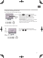
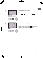
<Auto (dual set point) or Setback mode>
1
The current preset temperatures will appear.
Press the
F2
or
F3
button to display the Settings
screen.
Operation mode
Room
temperature
(Refer to the
Installation
Manual.)
Preset
temperature
for cooling
Preset
temperature
for heating

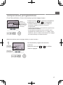
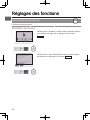
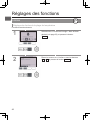
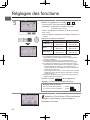
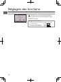
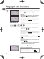
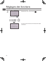
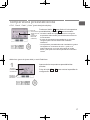
18
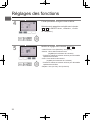
Basic operations
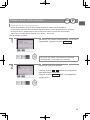
2
Press the
F1
or
F2
button to move the cursor to
the desired temperature setting (cooling or heating).
Press the
F3
button to decrease the selected
temperature, and press the
F4
button to increase.
•
Refer to the table below for the settable temperature
range for different operation modes.
•
The preset temperature settings for cooling and heating in
the Auto (dual set point) mode are also used by the Cool/
Drying and Heat modes.
•
The preset temperatures for cooling and heating in the
Auto (dual set point) mode must meet the conditions
below:
•
Preset cooling temperature is higher than preset heating temperature.
•
The minimum temperature difference requirement between cooling and
heating preset temperatures (varies with the models of indoor units
connected) is met.
•
If preset temperatures are set in a way that does not meet the minimum
temperature difference requirement, both preset temperatures will
automatically be changed within the allowable setting ranges.
Settable preset temperature range
Operation mode Preset temperature range
Cool/Drying 19 ~ 30 ºC (67 ~ 87 ºF)
Heat 17 ~ 28 ºC (63 ~ 83 ºF)
Auto (Single set point) 19 ~ 28 ºC (67 ~ 83 ºF)
Auto (Dual set points) [C ool]
Preset temperature range for the Cool mode
[H eat]
Preset temperature range for the Heat mode
Setback [C ool]
Preset temperature range for the Cool mode
[H eat]
Preset temperature range for the Heat mode
Fan/Ventilation Not settable
The settable temperature range varies with the model of indoor units.
Preset
temperature
for heating
Preset
temperature
for cooling
temperature

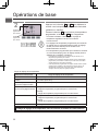
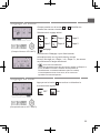
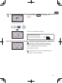
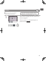
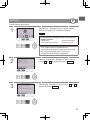
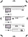
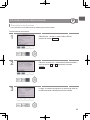
19
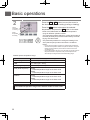
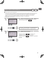
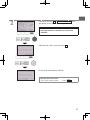
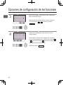
Fan speed
Each pressing of the
F4
button cycles through the following
fan speeds.
Auto
•
The available fan speeds depend on the models of connected
indoor units.
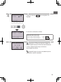
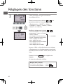
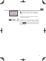
HOLD setting
Press the
SELECT/HOLD
button to enable/disable the HOLD
function.
If the HOLD function is enabled, the following functions will
be prohibited, and
will appear.
•
ON/OFF timer
•
Auto-Off timer
•
Weekly timer
•
Automatic return to the preset temperature

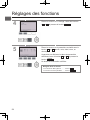
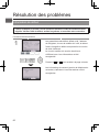
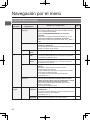
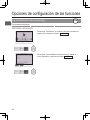
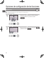
20
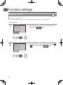
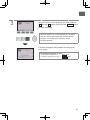
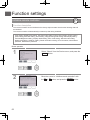
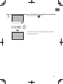
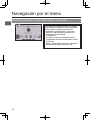
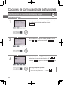
Navigating through the menu
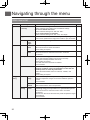
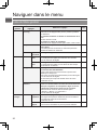
Main menu list
Main menu
Setting items Setting details
Page
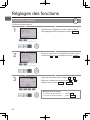
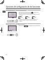
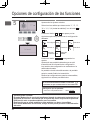
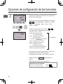
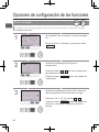
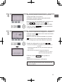
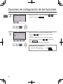
Operation Vane•Louver•Vent.
(Lossnay)
Use to set the vane angle.
•
Select a desired vane setting from five different settings.
Use to turn ON/OFF the louver.
•
Select a desired setting from “ON” and “OFF.”
Use to set the amount of ventilation.
•
Select a desired setting from “Off,” “Low,” and “High.”
23
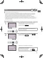
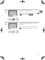
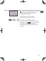
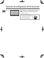
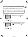
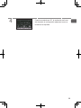
High power Use to reach the comfortable room temperature quickly.
•
Units can be operated in the High-power mode for up to 30 minutes.
26
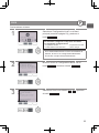
Comfort Manual
vane
angle
Use to fix each vane angle. 27
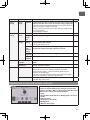
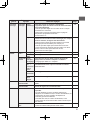
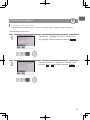
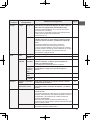
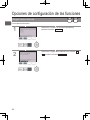
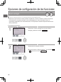
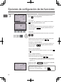
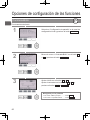
Timer Timer On/Off
timer
Use to set the operation On/Off times.
•
Time can be set in 5-minute increments.
*
Clock setting is required.
30
Auto-Off
timer
Use to set the Auto-Off time.
•
Time can be set to a value from 30 to 240 in 10-minute
increments.
33
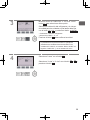
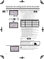
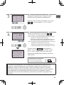
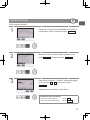
Weekly timer Use to set the weekly operation On/Off times.
•
Up to eight operation patterns can be set for each day.
•
Two types of weekly schedules can be set.
*
Clock setting is required.
*
Not valid when the On/Off timer is enabled.
*
1ºF increments
35
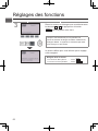
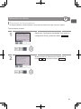
OU silent mode Use to set the time periods in which priority is given to quiet
operation of outdoor units over temperature control. Set the
Start/Stop times for each day of the week.
•
Select the desired silent level from “Normal,” “Middle,” and
“Quiet.”
*
Clock setting is required.
38
Energy
saving
Restriction
Temp.
range
Use to restrict the preset temperature range.
•
Different temperature ranges can be set for different operation
modes.
*
1ºF increments
41
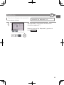
Operation
locked
Use to lock selected functions.
•
The locked functions cannot be operated.
44
Energy
saving
Auto
return
Use to get the units to operate at the preset temperature after
performing energy-save operation for a specified time period.
•
Time can be set to a value from 30 and 120 in 10-minute
increments.
*
This function will not be valid when the preset temperature ranges
are restricted.
*
1ºF increments
47
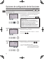
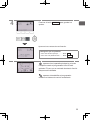
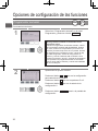
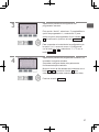
La page est en cours de chargement...
La page est en cours de chargement...
La page est en cours de chargement...
La page est en cours de chargement...
La page est en cours de chargement...
La page est en cours de chargement...
La page est en cours de chargement...
La page est en cours de chargement...
La page est en cours de chargement...
La page est en cours de chargement...
La page est en cours de chargement...
La page est en cours de chargement...
La page est en cours de chargement...
La page est en cours de chargement...
La page est en cours de chargement...
La page est en cours de chargement...
La page est en cours de chargement...
La page est en cours de chargement...
La page est en cours de chargement...
La page est en cours de chargement...
La page est en cours de chargement...
La page est en cours de chargement...
La page est en cours de chargement...
La page est en cours de chargement...
La page est en cours de chargement...
La page est en cours de chargement...
La page est en cours de chargement...
La page est en cours de chargement...
La page est en cours de chargement...
La page est en cours de chargement...
La page est en cours de chargement...
La page est en cours de chargement...
La page est en cours de chargement...
La page est en cours de chargement...
La page est en cours de chargement...
La page est en cours de chargement...
La page est en cours de chargement...
La page est en cours de chargement...
La page est en cours de chargement...
La page est en cours de chargement...
La page est en cours de chargement...
La page est en cours de chargement...
La page est en cours de chargement...
La page est en cours de chargement...
La page est en cours de chargement...
La page est en cours de chargement...
La page est en cours de chargement...
La page est en cours de chargement...
La page est en cours de chargement...
La page est en cours de chargement...
La page est en cours de chargement...
La page est en cours de chargement...
La page est en cours de chargement...
La page est en cours de chargement...
La page est en cours de chargement...
La page est en cours de chargement...
La page est en cours de chargement...
La page est en cours de chargement...
La page est en cours de chargement...
La page est en cours de chargement...
La page est en cours de chargement...
La page est en cours de chargement...
La page est en cours de chargement...
La page est en cours de chargement...
La page est en cours de chargement...
La page est en cours de chargement...
La page est en cours de chargement...
La page est en cours de chargement...
La page est en cours de chargement...
La page est en cours de chargement...
La page est en cours de chargement...
La page est en cours de chargement...
La page est en cours de chargement...
La page est en cours de chargement...
La page est en cours de chargement...
La page est en cours de chargement...
La page est en cours de chargement...
La page est en cours de chargement...
La page est en cours de chargement...
La page est en cours de chargement...
La page est en cours de chargement...
La page est en cours de chargement...
La page est en cours de chargement...
La page est en cours de chargement...
La page est en cours de chargement...
La page est en cours de chargement...
La page est en cours de chargement...
La page est en cours de chargement...
La page est en cours de chargement...
La page est en cours de chargement...
La page est en cours de chargement...
La page est en cours de chargement...
La page est en cours de chargement...
La page est en cours de chargement...
La page est en cours de chargement...
La page est en cours de chargement...
La page est en cours de chargement...
La page est en cours de chargement...
La page est en cours de chargement...
La page est en cours de chargement...
La page est en cours de chargement...
La page est en cours de chargement...
La page est en cours de chargement...
La page est en cours de chargement...
La page est en cours de chargement...
La page est en cours de chargement...
La page est en cours de chargement...
La page est en cours de chargement...
La page est en cours de chargement...
La page est en cours de chargement...
La page est en cours de chargement...
La page est en cours de chargement...
La page est en cours de chargement...
La page est en cours de chargement...
La page est en cours de chargement...
La page est en cours de chargement...
La page est en cours de chargement...
La page est en cours de chargement...
La page est en cours de chargement...
La page est en cours de chargement...
La page est en cours de chargement...
La page est en cours de chargement...
La page est en cours de chargement...
La page est en cours de chargement...
La page est en cours de chargement...
La page est en cours de chargement...
La page est en cours de chargement...
La page est en cours de chargement...
La page est en cours de chargement...
La page est en cours de chargement...
La page est en cours de chargement...
La page est en cours de chargement...
La page est en cours de chargement...
La page est en cours de chargement...
La page est en cours de chargement...
La page est en cours de chargement...
La page est en cours de chargement...
La page est en cours de chargement...
La page est en cours de chargement...
La page est en cours de chargement...
La page est en cours de chargement...
La page est en cours de chargement...
La page est en cours de chargement...
La page est en cours de chargement...
La page est en cours de chargement...
La page est en cours de chargement...
La page est en cours de chargement...
La page est en cours de chargement...
La page est en cours de chargement...
La page est en cours de chargement...
La page est en cours de chargement...
La page est en cours de chargement...
La page est en cours de chargement...
La page est en cours de chargement...
La page est en cours de chargement...
La page est en cours de chargement...
La page est en cours de chargement...
La page est en cours de chargement...
La page est en cours de chargement...
La page est en cours de chargement...
La page est en cours de chargement...
La page est en cours de chargement...
La page est en cours de chargement...
La page est en cours de chargement...
La page est en cours de chargement...
La page est en cours de chargement...
La page est en cours de chargement...
La page est en cours de chargement...
La page est en cours de chargement...
La page est en cours de chargement...
La page est en cours de chargement...
La page est en cours de chargement...
La page est en cours de chargement...
La page est en cours de chargement...
La page est en cours de chargement...
La page est en cours de chargement...
La page est en cours de chargement...
La page est en cours de chargement...
La page est en cours de chargement...
La page est en cours de chargement...
La page est en cours de chargement...
La page est en cours de chargement...
La page est en cours de chargement...
La page est en cours de chargement...
La page est en cours de chargement...
La page est en cours de chargement...
La page est en cours de chargement...
La page est en cours de chargement...
La page est en cours de chargement...
La page est en cours de chargement...
La page est en cours de chargement...
La page est en cours de chargement...
La page est en cours de chargement...
La page est en cours de chargement...
La page est en cours de chargement...
La page est en cours de chargement...
La page est en cours de chargement...
La page est en cours de chargement...
La page est en cours de chargement...
La page est en cours de chargement...
La page est en cours de chargement...
La page est en cours de chargement...
La page est en cours de chargement...
La page est en cours de chargement...
-
 1
1
-
 2
2
-
 3
3
-
 4
4
-
 5
5
-
 6
6
-
 7
7
-
 8
8
-
 9
9
-
 10
10
-
 11
11
-
 12
12
-
 13
13
-
 14
14
-
 15
15
-
 16
16
-
 17
17
-
 18
18
-
 19
19
-
 20
20
-
 21
21
-
 22
22
-
 23
23
-
 24
24
-
 25
25
-
 26
26
-
 27
27
-
 28
28
-
 29
29
-
 30
30
-
 31
31
-
 32
32
-
 33
33
-
 34
34
-
 35
35
-
 36
36
-
 37
37
-
 38
38
-
 39
39
-
 40
40
-
 41
41
-
 42
42
-
 43
43
-
 44
44
-
 45
45
-
 46
46
-
 47
47
-
 48
48
-
 49
49
-
 50
50
-
 51
51
-
 52
52
-
 53
53
-
 54
54
-
 55
55
-
 56
56
-
 57
57
-
 58
58
-
 59
59
-
 60
60
-
 61
61
-
 62
62
-
 63
63
-
 64
64
-
 65
65
-
 66
66
-
 67
67
-
 68
68
-
 69
69
-
 70
70
-
 71
71
-
 72
72
-
 73
73
-
 74
74
-
 75
75
-
 76
76
-
 77
77
-
 78
78
-
 79
79
-
 80
80
-
 81
81
-
 82
82
-
 83
83
-
 84
84
-
 85
85
-
 86
86
-
 87
87
-
 88
88
-
 89
89
-
 90
90
-
 91
91
-
 92
92
-
 93
93
-
 94
94
-
 95
95
-
 96
96
-
 97
97
-
 98
98
-
 99
99
-
 100
100
-
 101
101
-
 102
102
-
 103
103
-
 104
104
-
 105
105
-
 106
106
-
 107
107
-
 108
108
-
 109
109
-
 110
110
-
 111
111
-
 112
112
-
 113
113
-
 114
114
-
 115
115
-
 116
116
-
 117
117
-
 118
118
-
 119
119
-
 120
120
-
 121
121
-
 122
122
-
 123
123
-
 124
124
-
 125
125
-
 126
126
-
 127
127
-
 128
128
-
 129
129
-
 130
130
-
 131
131
-
 132
132
-
 133
133
-
 134
134
-
 135
135
-
 136
136
-
 137
137
-
 138
138
-
 139
139
-
 140
140
-
 141
141
-
 142
142
-
 143
143
-
 144
144
-
 145
145
-
 146
146
-
 147
147
-
 148
148
-
 149
149
-
 150
150
-
 151
151
-
 152
152
-
 153
153
-
 154
154
-
 155
155
-
 156
156
-
 157
157
-
 158
158
-
 159
159
-
 160
160
-
 161
161
-
 162
162
-
 163
163
-
 164
164
-
 165
165
-
 166
166
-
 167
167
-
 168
168
-
 169
169
-
 170
170
-
 171
171
-
 172
172
-
 173
173
-
 174
174
-
 175
175
-
 176
176
-
 177
177
-
 178
178
-
 179
179
-
 180
180
-
 181
181
-
 182
182
-
 183
183
-
 184
184
-
 185
185
-
 186
186
-
 187
187
-
 188
188
-
 189
189
-
 190
190
-
 191
191
-
 192
192
-
 193
193
-
 194
194
-
 195
195
-
 196
196
-
 197
197
-
 198
198
-
 199
199
-
 200
200
-
 201
201
-
 202
202
-
 203
203
-
 204
204
-
 205
205
-
 206
206
-
 207
207
-
 208
208
-
 209
209
-
 210
210
-
 211
211
-
 212
212
-
 213
213
-
 214
214
-
 215
215
-
 216
216
-
 217
217
-
 218
218
-
 219
219
-
 220
220
-
 221
221
-
 222
222
-
 223
223
-
 224
224


Mitsubishi Electric PAR-40MAAU Le manuel du propriétaire
- Taper
- Le manuel du propriétaire
dans d''autres langues
Documents connexes
-
Mitsubishi Electric PKA-A30KA7 Le manuel du propriétaire
-
Mitsubishi Electric PVFY-P08 Le manuel du propriétaire
-
Mitsubishi Electric PAC-YT53CRAU Guide d'installation
-
Mitsubishi Electric PKA-M·LA(L)2 Series Air Conditioners Indoor unit Manuel utilisateur
-
Mitsubishi Electric PLA-A30EA7 Le manuel du propriétaire
-
Mitsubishi Electric PZ-62DR-E Manuel utilisateur
-
-
Mitsubishi SEZ-KD12NA4R1.TH Le manuel du propriétaire
-
Mitsubishi Electric Electric Air Distribution Grille Indoor Cassette Le manuel du propriétaire
-
