AVENTICS Pneumatic piston rod cylinders (ATEX) Mode d'emploi
- Taper
- Mode d'emploi

Betriebsanleitung | Operating instructions | Notice d’instruction
Istruzioni per l'uso | Instrucciones de servicio | Bruksanvisning
R412005817-BAL-001-AJ
2020-10, Replaces: 2020-09
DE/EN/FR/IT/ES/SV
AVENTICS™
Pneumatische Kolbenstangenzylinder (ATEX)
Pneumatic Piston Rod Cylinders (ATEX)
Vérins à tige pneumatiques (ATEX)
Cilindri pneumatici con asta (ATEX)
Cilindros de vástago neumáticos (ATEX)
Pneumatiska kolvstångscylindrar (ATEX)
II 2G Ex h IIC T4 Gb
II 2D Ex h IIIC T135°C Db X

AVENTICS™ | R412005817-BAL-001-AJ | Deutsch 2
Inhaltsverzeichnis
1 Zu dieser Dokumentation.................................................................................................................................................................................................. 3
1.1 Gültigkeit der Dokumentation .......................................................................................................................................................................................... 3
1.2 Erforderliche und ergänzende Dokumentationen ............................................................................................................................................................. 3
1.3 Darstellung von Informationen ......................................................................................................................................................................................... 3
1.3.1 Warnhinweise .................................................................................................................................................................................................... 3
2 Sicherheitshinweise........................................................................................................................................................................................................... 3
2.1 Zu diesem Kapitel ............................................................................................................................................................................................................. 3
2.2 Bestimmungsgemäße Verwendung.................................................................................................................................................................................. 3
2.3 Nicht bestimmungsgemäße Verwendung ........................................................................................................................................................................ 3
2.4 Qualifikation des Personals ............................................................................................................................................................................................... 3
2.5 Allgemeine Sicherheitshinweise........................................................................................................................................................................................ 3
2.6 Produkt- und technologieabhängige Sicherheitshinweise................................................................................................................................................. 4
2.7 Pflichten des Betreibers..................................................................................................................................................................................................... 4
3 Allgemeine Hinweise zu Sachschäden und Produktschäden............................................................................................................................................... 4
4 Einsatz in explosionsgefährdeten Bereichen ...................................................................................................................................................................... 4
4.1 ATEX-Kennzeichnung........................................................................................................................................................................................................ 4
5 Lieferumfang..................................................................................................................................................................................................................... 5
6 Zu diesem Produkt ............................................................................................................................................................................................................ 5
6.1 Identifikation des Produkts ............................................................................................................................................................................................... 5
7 Montage............................................................................................................................................................................................................................ 5
7.1 Einbaubedingungen.......................................................................................................................................................................................................... 6
7.2 Zylinder montieren ........................................................................................................................................................................................................... 6
8 Inbetriebnahme................................................................................................................................................................................................................. 6
8.1 Geschwindigkeit einstellen ............................................................................................................................................................................................... 6
8.2 Pneumatische Endlagendämpfungen einstellen................................................................................................................................................................ 7
8.2.1 Grundeinstellung ............................................................................................................................................................................................... 7
8.2.2 Einstellungen für beide Seiten ............................................................................................................................................................................ 7
9 Pflege und Wartung .......................................................................................................................................................................................................... 8
10 Demontage und Entsorgung.............................................................................................................................................................................................. 8
10.1 Zylinder demontieren ....................................................................................................................................................................................................... 8
10.2 Zylinder entsorgen............................................................................................................................................................................................................ 8
11 Fehlersuche und Fehlerbehebung...................................................................................................................................................................................... 8
12 Technische Daten .............................................................................................................................................................................................................. 8
13 Zubehör ............................................................................................................................................................................................................................ 8
14 Konformitätserklärung...................................................................................................................................................................................................... 8

1 Zu dieser Dokumentation
1.1 Gültigkeit der Dokumentation
Diese Dokumentation gilt für folgende doppeltwirkende pneumatische Kolben-
stangenzylinder:
• Zugankerzylinder nach ISO 15552, Serie ITS und TRB
• Profilzylinder nach ISO 15552, Serie CCL-IS und PRA
• Kompaktzylinder, Serie KPZ
• Kompaktzylinder nach ISO 21287, Serie CCI und CCL-IC
• Minizylinder nach ISO 6432, Serie MNI
• Rundzylinder, Serie CSL-RD und RPC
Diese Dokumentation richtet sich an Anlagenplaner, Anlagenbetreiber und Mon-
teure.
u Lesen Sie diese Dokumentation vollständig und insbesondere das Kapitel „Si-
cherheitshinweise“, bevor Sie mit dem Produkt arbeiten.
1.2 Erforderliche und ergänzende Dokumentationen
u Nehmen Sie das Produkt erst in Betrieb, wenn Ihnen die Anlagendokumentati-
on vorliegt und Sie diese verstanden und beachtet haben.
1.3 Darstellung von Informationen
Damit Sie mit dieser Dokumentation schnell und sicher mit Ihrem Produkt arbei-
ten können, werden einheitliche Warnhinweise, Symbole, Begriffe und Abkürzun-
gen verwendet. Zum besseren Verständnis sind diese in den folgenden Abschnit-
ten erklärt.
1.3.1 Warnhinweise
In dieser Dokumentation stehen Warnhinweise vor einer Handlungsabfolge, bei
der die Gefahr von Personen- oder Sachschäden besteht. Die beschriebenen
Maßnahmen zur Gefahrenabwehr müssen eingehalten werden.
Warnhinweise sind wie folgt aufgebaut:
Aufbau von Warnhinweisen
SIGNALWORT
Art und Quelle der Gefahr
Folgen bei Nichtbeachtung
u Maßnahmen zur Gefahrenabwehr
Bedeutung der Signalwörter
GEFAHR
Unmittelbar drohende Gefahr für das Leben und die Gesundheit von Personen.
Das Nichtbeachten dieser Hinweise hat schwere gesundheitliche Auswirkun-
gen zur Folge, bis hin zum Tod.
VORSICHT
Möglicherweise gefährliche Situation.
Das Nichtbeachten dieser Hinweise kann leichte Verletzungen zur Folge haben
oder zu Sachbeschädigungen führen.
ACHTUNG
Möglichkeit von Sachbeschädigungen oder Funktionsstörungen.
Das Nichtbeachten dieser Hinweise kann Sachbeschädigungen oder Funktions-
störungen zur Folge haben, jedoch keine Personenschäden.
2 Sicherheitshinweise
2.1 Zu diesem Kapitel
Das Produkt wurde gemäß den allgemein anerkannten Regeln der Technik her-
gestellt. Trotzdem besteht die Gefahr von Personen- und Sachschäden, wenn Sie
dieses Kapitel und die Sicherheitshinweise in dieser Dokumentation nicht beach-
ten.
1. Lesen Sie diese Dokumentation gründlich und vollständig, bevor Sie mit dem
Produkt arbeiten.
2. Bewahren Sie die Dokumentation so auf, dass sie jederzeit für alle Benutzer
zugänglich ist.
3. Geben Sie das Produkt an Dritte stets zusammen mit den erforderlichen Do-
kumentationen weiter.
2.2 Bestimmungsgemäße Verwendung
Das Produkt ist eine pneumatische Anlagenkomponente zum Bewegen von Mas-
sen und zur Übertragung von Zug- bzw. Druckkräften.
Das Produkt ist für den professionellen Gebrauch und nicht für die private Ver-
wendung bestimmt.
Das Produkt entspricht den Anforderungen der ATEX- Richtlinie 2014/34/
EU und darf bestimmungsgemäß unter Berücksichtigung der geltenden
Errichtungsbestimmungen für Geräte und Anlagen in explosionsgefährde-
ten Bereichen wie folgt eingesetzt werden:
• In den Zonen 1 und 2 (Gas-Ex, Kategorie 2G und 3G) in den Explosionsgrup-
pen IIA, IIB und IIC, Temperaturklasse 4
• In den Zonen 21 und 22 (Staub-Ex, Kategorie 2D und 3D) in den Explosions-
gruppen IIIA, IIIB und IIIC, Temperaturklasse 135°C
Die bestimmungsgemäße Verwendung schließt auch ein, dass Sie diese Doku-
mentation und insbesondere das Kapitel „Sicherheitshinweise“ vollständig gele-
sen und verstanden haben.
2.3 Nicht bestimmungsgemäße Verwendung
Jeder andere Gebrauch als in der bestimmungsgemäßen Verwendung beschrie-
ben ist nicht bestimmungsgemäß und deshalb unzulässig.
Für Schäden bei nicht bestimmungsgemäßer Verwendung übernimmt die
AVENTICS GmbH keine Haftung. Die Risiken bei nicht bestimmungsgemäßer
Verwendung liegen allein beim Benutzer.
Zur nicht bestimmungsgemäßen Verwendung des Produkts gehört,
• der Betrieb in Bereichen des Schlagwetterschutzes,
• wenn das Produkt als Feder oder Dämpfungselement eingesetzt wird, da es
dadurch zu unzulässigen Belastungen kommen kann.
2.4 Qualifikation des Personals
Die in dieser Dokumentation beschriebenen Tätigkeiten erfordern grundlegende
Kenntnisse der Mechanik und Pneumatik sowie Kenntnisse der zugehörigen
Fachbegriffe. Um die sichere Verwendung zu gewährleisten, dürfen diese Tätig-
keiten daher nur von einer entsprechenden Fachkraft oder einer unterwiesenen
Person unter Leitung einer Fachkraft durchgeführt werden.
Eine Fachkraft ist, wer aufgrund seiner fachlichen Ausbildung, seiner Kenntnisse
und Erfahrungen sowie seiner Kenntnisse der einschlägigen Bestimmungen die
ihm übertragenen Arbeiten beurteilen, mögliche Gefahren erkennen und geeig-
nete Sicherheitsmaßnahmen treffen kann. Eine Fachkraft muss die einschlägigen
fachspezifischen Regeln einhalten.
2.5 Allgemeine Sicherheitshinweise
• Beachten Sie die gültigen Vorschriften zur Unfallverhütung und zum Umwelt-
schutz.
• Berücksichtigen Sie die Bestimmungen für explosionsgefährdete Bereiche im
Anwenderland.
• Beachten Sie die Sicherheitsvorschriften und -bestimmungen des Landes, in
dem das Produkt eingesetzt/angewendet wird.
• Verwenden Sie AVENTICS-Produkte nur in technisch einwandfreiem Zustand.
• Beachten Sie alle Hinweise auf dem Produkt.
• Personen, die AVENTICS-Produkte montieren, bedienen, demontieren oder
warten, dürfen nicht unter dem Einfluss von Alkohol, sonstigen Drogen oder
Medikamenten, die die Reaktionsfähigkeit beeinflussen, stehen.
• Verwenden Sie nur vom Hersteller zugelassene Zubehör- und Ersatzteile, um
Personengefährdungen wegen nicht geeigneter Ersatzteile auszuschließen.
• Halten Sie die in der Produktdokumentation angegebenen technischen Daten
und Umgebungsbedingungen ein.
• Wenn in sicherheitsrelevanten Anwendungen ungeeignete Produkte einge-
baut oder verwendet werden, können unbeabsichtigte Betriebszustände in
der Anwendung auftreten, die Personen- und/oder Sachschäden verursachen
können. Setzen Sie daher ein Produkt nur dann in sicherheitsrelevante Anwen-
AVENTICS™ | R412005817-BAL-001-AJ | Deutsch 3

dungen ein, wenn diese Verwendung ausdrücklich in der Dokumentation des
Produkts spezifiziert und erlaubt ist.
• Sie dürfen das Produkt erst dann in Betrieb nehmen, wenn festgestellt wurde,
dass das Endprodukt (beispielsweise eine Maschine oder Anlage), in das die
AVENTICS-Produkte eingebaut sind, den länderspezifischen Bestimmungen,
Sicherheitsvorschriften und Normen der Anwendung entspricht.
2.6 Produkt- und technologieabhängige Sicherheitshinweise
GEFAHR
Explosionsgefahr beim Arbeiten in explosionsfähiger Atmosphäre!
Wenn die Anlage, in die das Produkt eingebaut werden soll, von explosionsfä-
higer Atmosphäre umgeben ist, kann sich dieses beim Arbeiten entzünden.
1. Berücksichtigen Sie immer die lokalen Errichtungsbestimmungen.
2. Führen Sie Arbeiten nur in explosionsfreier Atmosphäre und bei vorliegen-
dem Feuer-Erlaubnisschein durch. Wenn Sie trotzdem mit dem Vorhanden-
sein von explosionsfähiger Atmosphäre rechnen müssen, verwenden Sie
nur nicht funkendes Werkzeug.
GEFAHR
Explosionsgefahr durch elektrostatische Aufladung!
Eine elektrostatische Aufladung des Produkts kann zu Funkenbildung führen
und stellt in Ex-Schutzzonen eine Explosionsgefahr dar.
u Vermeiden Sie eine elektrostatische Aufladung, z. B. indem Sie das Produkt
erden.
GEFAHR
Funkenbildung aufgrund von mechanischen Belastungen!
Mechanische Belastungen führen zu Funkenbildung und stellen eine Explosi-
onsgefahr dar.
1. Sie dürfen den Zylinder niemals verdrehen, biegen oder unter Spannung
befestigen.
2. Setzen Sie den Zylinder während Transport, Montage und Betrieb niemals
Schlagkräften aus.
3. Bauen Sie den Zylinder so ein, dass er vor Stoßenergie geschützt ist, die
während des Betriebs von außen auf das Gehäuse einwirken kann.
4. Vermeiden Sie Schwingungen, z. B. indem Sie die Anlage auf einen ge-
dämpften Sockel aufstellen.
GEFAHR
Explosionsgefahr durch Funkenbildung!
Einige Kolbenstangenaufsätze und Befestigungselemente lassen oszillierende
Dreh- und Schwenkbewegungen der Zylinder zu. Die Verwendung dieser Ele-
mente als Radialgleitlager mit Umfangsgeschwindigkeiten größer als 1 m/s
führt zu einer unzulässigen Erwärmung. Bei zu hoher Erwärmung entstehen
Reibfunken, die eine Explosionsgefahr darstellen.
u Stellen Sie sicher, dass Umfangsgeschwindigkeiten an den Reibflächen ma-
ximal 1 m/s betragen.
VORSICHT
Unsachgemäß verlegte Druckluftleitungen!
Verletzungsgefahr!
u Verlegen Sie die Druckluftleitungen so, dass niemand darüber stolpern
kann.
VORSICHT
Herabfallende Nutzlast!
Bei vertikaler Einbaulage des Zylinders kann eine angehängte Last herabfallen,
wenn die Druckluftzufuhr abgeschaltet wird.
u Sichern Sie den Zugangsbereich unter einer angehängten Last stets ab.
2.7 Pflichten des Betreibers
Als Betreiber der Anlage, die mit ATEX-Zylindern ausgestattet werden soll, sind
Sie dafür verantwortlich,
• dass die bestimmungsgemäße Verwendung sichergestellt ist,
• dass das Bedienpersonal regelmäßig unterwiesen wird,
• dass die Einsatzbedingungen den Anforderungen an die sichere Verwendung
des Produktes entsprechen,
• dass Reinigungsintervalle gemäß den Umweltbeanspruchungen am Ein-
satzort festgelegt und eingehalten werden,
• dass Zündgefahren, die durch den Einbau von Betriebsmitteln in Ihrer Anlage
entstehen, berücksichtigt werden,
• dass bei einem aufgetretenen Defekt keine eigenmächtigen Reparaturversu-
che unternommen werden.
3 Allgemeine Hinweise zu Sachschäden und Pro-
duktschäden
ACHTUNG
Mechanische Belastungen!
Beschädigung des Zylinders!
1. Sie dürfen den Zylinder nicht verdrehen, biegen oder unter Spannung be-
festigen.
2. Vermeiden Sie beim Anschließen der Schläuche mechanische Spannungen.
3. Achten Sie darauf, dass der Zylinder nicht durch herabfallende Teile oder
den falschen Umgang mit Werkzeugen beschädigt wird. Insbesondere die
Kolbenstange und die Dichtungen dürfen nicht beschädigt werden. Bauen
Sie den Zylinder ggf. geschützt ein.
ACHTUNG
Versehentliches Lösen der durchgehenden Kolbenstange!
Wenn die durchgehende Kolbenstange des Zylinders verschraubt ist, kann sie
bei der Montage versehentlich gelöst werden.
1. Kontern Sie bei Schraubarbeiten an der Kolbenstange stets an einem An-
griffspunkt auf derselben Seite des Zylinders.
2. Führen Sie niemals gegenläufige Konterungen oder Drehbewegungen an
beiden Enden der Kolbenstange aus.
3. Beachten Sie den Warnaufkleber.
4 Einsatz in explosionsgefährdeten Bereichen
Zylinder mit ATEX-Kennzeichnung auf dem Typenschild sind für den Einsatz in ex-
plosionsgefährdeten Bereichen ausgelegt. Alle außenliegenden Werkstoffe be-
stehen aus funkenarmen Materialien.
1. Beachten Sie stets die technischen Daten und die auf dem Typenschild ange-
gebenen Grenzwerte, insbesondere die Daten aus der ATEX-Kennzeichnung.
2. Verwenden Sie als Druckmedium außerhalb des Ex-Bereiches erzeugte und
aufbereitete Druckluft gemäß ISO 8537-1.
3. Verwenden Sie als Druckmedium ausschließlich Druckluft, die den Zylinder
und die beinhaltenden Dichtwerkstoffe nicht angreift.
4.1 ATEX-Kennzeichnung
II 2G Ex h IIC T4 Gb
II 2D Ex h IIIC T135°C Db X
Das Produkt entspricht den Anforderungen der ATEX-Richtlinie 2014/34/EU. Im
Folgenden sind die Merkmale und Einsatzbereiche, die aus der ATEX-Kennzeich-
nung hervorgehen, erläutert:
II alle Bereiche, außer Bergbau
2G Zone 1, 2, Gas-Ex: Kategorie 2G, 3G
2D Zone 21, 22, Staub-Ex: Kategorie 2D, 3D
Ex h Zündschutzart, h: Symbol für Standard
IIC für den Explosionsbereich IIA, IIB und IIC geeignet
AVENTICS™ | R412005817-BAL-001-AJ | Deutsch 4

T4 Temperaturklasse 4 (Gas-Ex)
Zündtemperatur brennbarer Stoffe > 135 °C
max. zulässige Oberflächentemperatur 135 °C
IIIC für den Explosionsbereich IIIA, IIIB und IIIC geeignet
T135° maximale Oberflächentemperatur (Staub-Ex)
Gb, Db Gerätekategorie und Geräteschutzniveau
X besondere Merkmale Technische Daten (Thermischer Anwendungsbereich)
5 Lieferumfang
• 1x Zylinder gemäß Katalog- oder Konfiguratorangaben
• 1x Betriebsanleitung
• Optional: Befestigungselemente
Wenn Sie einen Zylinder mit Befestigungselementen konfiguriert haben, sind die-
se Elemente bereits am Zylinder montiert. Das für Ihre Konfiguration zugelassene
Zubehör und Ersatzteile entnehmen Sie dem Online-Katalog.
Ihr Zylinder wurde nach Ihren Anforderungen individuell konfiguriert.
Die genaue Konfiguration können Sie sich mit Ihrer Bestellnummer im
Internet-Konfigurator anzeigen lassen.
6 Zu diesem Produkt
Auf der Titelseite sind Beispiele von Kolbenstangenzylindern dargestellt.
6.1 Identifikation des Produkts
Auf dem Standard-Typenschild finden Sie folgende Informationen (die dargestell-
ten Typenschilder sind nur Muster):
00135419
1 2 3
4
7 6 58
Abb.1: Standard-Typenschild
1 Herstellerlogo 5 Maximaler Druck
2 Fertigendes Werk 6 Hub
3 Fertigungsdatum 7 Seriennummer (MNR)
4 Hergestellt in 8 Serie
1
9
2 3
6 5 4
7
8
Abb.2: Standard-Typenschild, Serie CCL-IS und RPC
1 Herstellerlogo 6 Hub
2 Seriennummer (MNR) 7 Hergestellt in
3 QR-Code (optional) 8 Fertigungsdatum
4 Maximaler Druck 9 Serie
5 Fertigendes Werk
Auf dem Typenschild für den mechanischen Explosionsschutz finden Sie folgende
Informationen:
1
2
3
4
5
Abb.3: Typenschild für den mechanischen Explosionsschutz
1 TFR (Technical File Reference Num-
ber)
4 ATEX-Kennzeichnung
2 CE-Kennzeichnung 5 ATEX-Symbol
3 Achtung: Besondere Merkmale Tech-
nische Daten
u Überprüfen Sie anhand der Materialnummer, die auf dem Gehäuse aufge-
druckt ist, ob der Zylinder mit Ihrer Bestellung übereinstimmt.
7 Montage
GEFAHR
Explosionsgefahr durch Überhitzung!
Das Produkt entwickelt während des Betriebs Wärme. Durch falschen Einbau
kann sich das Produkt überhitzen.
1. Achten Sie auf ausreichenden Abstand zu benachbarten Bauteilen, so dass
genügend Luft um das Produkt zirkulieren kann.
2. Schirmen Sie das Produkt ab, wenn Sie ihn in der Nähe von Wärmequellen
einbauen.
GEFAHR
Explosionsgefahr bei fehlender Erdung!
Ausgleichs- und Fehlerströme können die Temperatur der Bauteile erhöhen
und ggf. Funken erzeugen.
1. Erden Sie das Gehäuse und die Kolbenstange elektrisch leitend mit der An-
lage.
2. Erden Sie die Anlage nach den geltenden Vorschriften.
GEFAHR
Explosionsgefahr durch elektrostatische Aufladung der Schlauchoberfläche!
Große Schlauchdurchmesser erhöhen die Gefahr der elektrostatischen Aufla-
dung der Schlauchoberfläche. Elektrostatische Entladungen können zu Explo-
sionen führen.
u Verwenden Sie für den Anschluss der Zylinder nur Schläuche mit folgenden
Außendurchmessern:
Zylinder-Ø bis 25 mm: max. 6 mm
Zylinder-Ø 32 mm oder größer: beliebig
GEFAHR
Explosionsgefahr durch unzulässige Verschlauchung!
Lange Schläuche erwärmen sich im Betrieb übermäßig. Die Erwärmung der
Schläuche kann zu Explosionen führen.
u Verwenden Sie folgende Schlauchlängen:
Zylinder-Ø bis 25 mm: max. 5 m
Zylinder-Ø 32 mm oder größer: max. 10 m
GEFAHR
Explosionsgefahr durch aufgewirbelten Staub!
Aufgewirbelter Staub kann Explosionen verursachen.
u Stellen Sie sicher, dass Druckluft bzw. Abluft entweder über Schlauchleitun-
gen aus dem Ex-Bereich herausgeführt werden oder die Abluftleitungen so
montiert werden, dass der eingedrungene Staub immer abgeblasen wird.
AVENTICS™ | R412005817-BAL-001-AJ | Deutsch 5

GEFAHR
Explosionsgefahr durch Zirkulationsströme!
Magnetische Streufelder können Zirkulationsströme verursachen, z. B. in der
Nähe von elektrischen Antrieben bei unsymmetrischer Last, bei Elektroschwei-
ßen, wenn die Masse über die Anlage und nicht über eine 0 V-Leitung geleitet
wird oder bei kathodischem Korrosionsschutz.
u Stellen Sie sicher, dass ein Schutz gegen mögliche Effekte von Zirkulati-
onsströmen besteht, z. B. indem Sie das Produkt erden.
ACHTUNG
Offene Pneumatikanschlüsse!
Verschmutzung des Zylinderinnenraums!
u Entfernen Sie die Verschlussstopfen erst unmittelbar, bevor Sie die Ver-
schlauchung anschließen.
ACHTUNG
Falsche Befestigung des Zylinders!
Beschädigung des Zylinders!
1. Stellen Sie den ordnungsgemäßen Einbau des Zylinders und der Zubehör-
teile sicher.
2. Beachten Sie die maximalen Anzugsmomente und überprüfen Sie den fes-
ten Sitz aller Schrauben.
7.1 Einbaubedingungen
Der Zylinder hat eine Lebensdauerschmierung.
u Verwenden Sie vorzugsweise ungeölte Druckluft.
Druckluftqualität: siehe „Technische Daten“.
7.2 Zylinder montieren
1. Schalten Sie alle relevanten Anlagenteile spannungsfrei und drucklos, bevor
Sie den Zylinder montieren. Sichern Sie die Anlage gegen Wiedereinschalten.
Sie können das Produkt je nach Ihrer Konfiguration auf verschiedene Arten befes-
tigen. Im Lieferumfang ist nur die Befestigung enthalten, die Sie im Konfigurator
gewählt haben.
– Entnehmen Sie die genauen Abmessungen der Befestigungen für Ihren Zy-
linder dem Online-Katalog.
– Bauen Sie den Zylinder so in Ihren Anlagenteil ein, dass Sie die pneumati-
schen Anschlüsse und, falls vorhanden, die Drosselschrauben für die End-
lagendämpfung immer erreichen können.
2. Befestigen Sie den Zylinder so an der Halterung Ihres Anlagenteils, dass er
nicht unter Spannung steht. Beachten Sie dabei die maximal zulässigen An-
zugsmomente im Online-Katalog. Falls keine Angaben gemacht werden oder
Sie eigenes Befestigungsmaterial verwenden, gelten die allgemeinen Regeln
der Technik.
3. Entfernen Sie die Verschlussstopfen an den Pneumatikanschlüssen.
4. Schließen Sie die pneumatischen Anschlüsse des Zylinders an. Im Online-Kata-
log finden Sie pneumatische Verbindungstechnik zur Verschlauchung des Zy-
linders.
5. Befestigen Sie die Nutzlast an der Kolbenstange. Je nach Konfiguration kön-
nen Sie die Nutzlast am Innengewinde oder am Außengewinde befestigen.
Beachten Sie die zulässigen Kolbenkräfte.
Sie finden die max. zulässigen Kolbenkräfte im Online-Katalog.
Bei doppeltwirkenden Zylindern ist durch die Kolbenstange des Zylin-
ders die wirksame Kolbenfläche / Kolbenkraft beim Einfahren kleiner
als beim Ausfahren. Dies gilt nicht für Zylinder mit durchgehender Kol-
benstange.
8 Inbetriebnahme
GEFAHR
Explosionsgefahr durch Wärmeentwicklung!
Der Zylinder entwickelt während des Betriebs Wärme. Wenn vorgegebene
Grenzwerte überschritten werden, ist der Explosionsschutz nicht mehr ge-
währleistet.
u Beachten Sie die unter „Technische Daten“ und auf den Typenschildern an-
gegebenen Grenzwerte.
GEFAHR
Explosionsgefahr durch zu hohe Betriebsfrequenzen und Kolbengeschwin-
digkeiten!
Zu hohe Betriebsfrequenzen und Kolbengeschwindigkeiten erwärmen den Zy-
linder unzulässig und stellen eine Explosionsgefahr dar.
1. Überschreiten Sie niemals die maximal zulässige Doppelhub-Frequenz:
Zylinder-Ø bis 25mm: 0,33Hz
Zylinder-Ø32mm oder größer: 0,4Hz
2. Überschreiten Sie niemals die maximal zulässige Kolbengeschwindigkeit
von 1m/s.
VORSICHT
Verbrennungsgefahr durch heiße Oberflächen!
Berühren der Oberflächen des Produkts im laufenden Betrieb kann zu Verbren-
nungen führen.
1. Lassen Sie das Produkt abkühlen, bevor an ihm arbeiten.
2. Berühren Sie das Produkt nicht im Betrieb.
VORSICHT
Gefahr durch Lärm!
Gehörschäden durch Abluft- und Aufschlaggeräusche
u Stellen Sie die Endlagendämpfung richtig ein.
VORSICHT
Gefahr durch plötzlich freigesetzte Druckluft!
Unkontrollierte Bewegungen der Kolbenstange!
1. Stellen Sie sicher, dass niemand in den Verfahrensbereich der Anlage grei-
fen kann und keine Gegenstände hineinragen.
2. Montieren Sie ggf. eine Schutzeinrichtung.
3. Belüften Sie die Anlage langsam bis zum vorgesehenen Betriebsdruck.
8.1 Geschwindigkeit einstellen
GEFAHR
Explosionsgefahr durch Wärmeentwicklung!
Zu hohe Kolbengeschwindigkeiten erwärmen den Zylinder unzulässig und stel-
len eine Explosionsgefahr dar.
u Überschreiten Sie niemals die maximal zulässige Kolbengeschwindigkeit
von 1m/s.
VORSICHT
Gefahr von Personen- oder Sachschäden!
Ein Zylinder, der ohne Geschwindigkeitssteuerung betrieben wird, kann eine
hohe Kolbengeschwindigkeit erreichen und Verletzungen oder einen Maschi-
nenschaden verursachen.
u Stellen Sie sicher, dass der Zylinder immer mit Geschwindigkeitssteuerung
betrieben wird, z.B. durch Drosselrückschlagventile mit Abluftdrosselung.
Die Geschwindigkeit wird normalerweise gesteuert, indem die Abluft aus den Zy-
linderkammern gedrosselt wird, z. B. durch Drosselrückschlagventile mit Abluft-
drosselung.
AVENTICS™ | R412005817-BAL-001-AJ | Deutsch 6

ACHTUNG
Beschädigung des Zylinders durch zu tiefes Einschrauben der Drosselrück-
schlagventile!
1. Achten Sie auf die Gewindelänge der Drosselrückschlagventile, wenn Sie
diese direkt in den Zylinderdeckeln montieren.
2. Beachten Sie die Schlüsselflächen und Schlüsselweiten.
Beim Einstellen der Geschwindigkeit muss der Zylinder wie im Normalbetrieb be-
lastet und die Geschwindigkeit allmählich auf die gewünschte Betriebsgeschwin-
digkeit erhöht werden.
u Stellen Sie die Betriebsgeschwindigkeit nicht höher ein als nötig. Die Ge-
schwindigkeit muss an die Belastung des Zylinders angepasst werden, damit
die maximal zulässige Dämpfungsenergie nicht überschritten wird. Nutzen
Sie das Berechnungsprogramm im Online-Katalog.
Stellen Sie die Kolbengeschwindigkeit wie folgt ein:
1. Vergewissern Sie sich, dass kein Druck anliegt, und erhöhen Sie den Druck
dann langsam auf den gewünschten Betriebsdruck.
2. Öffnen Sie die Drosselrückschlagventile ein wenig.
3. Erhöhen Sie die Kolbengeschwindigkeit, indem Sie die Drosselrückschlagven-
tile langsam weiter öffnen, bis die gewünschte Betriebsgeschwindigkeit er-
reicht wird.
8.2 Pneumatische Endlagendämpfungen einstellen
Wenn Sie die Kolbengeschwindigkeit, die bewegte Masse oder den Be-
triebsdruck verändern, müssen Sie die pneumatischen Endlagendämp-
fungen neu einstellen.
Abb.4: Endlagendämpfung einstellen
Je nach Konfiguration ist Ihr Zylinder mit zwei pneumatischen Endlagendämpfun-
gen ausgestattet. Die Endlagendämpfungen werden mit Drosselschrauben an
beiden Enden des Zylinders eingestellt.
8.2.1 Grundeinstellung
u Drehen Sie beide Drosselschrauben im Uhrzeigersinn bis zum Anschlag hinein
und dann wieder eine volle Umdrehung heraus.
Damit verhindern Sie, dass der Kolben ungedämpft aufschlägt.
ACHTUNG
Hohe mechanische Belastung des Zylinders durch fehlerhafte Grundeinstel-
lung!
Der Zylinder kann beschädigt werden, wenn der Kolben ungedämpft auf-
schlägt.
u Führen Sie immer die Grundeinstellung durch.
8.2.2 Einstellungen für beide Seiten
Abb.5: Einstellung der Endlagendämpfung
Sie müssen die Dämpfungen immer an beiden Seiten des Zylinders einstellen. Die
Einstellreihenfolge ist beliebig.
einfahrende Kolbenstange
ausfahrende Kolbenstange
1. Fahren Sie den Kolben wiederholt von Endlage zu Endlage. Achten Sie hierbei
auf das Anschlaggeräusch des Kolbens (nachfolgend Schallpegel genannt)
und das Schwingungsverhalten (nachfolgend bewegte Masse genannt) des
Gesamtsystems beim Eintritt in die Dämpfungsphase.
ð Der Schallpegel ist deutlich hörbar.
ð Die bewegte Masse schwingt merklich.
2. Drehen Sie die Drosselschrauben langsam heraus. Damit verringern Sie die
Dämpfung.
Abb.6: Drosselschrauben herausdrehen
3. Fahren Sie den Kolben wiederholt von Endlage zu Endlage. Nehmen Sie dabei
den Schallpegel des Kolbenanschlags und das Schwingungsverhalten der be-
wegten Masse wahr:
ð Der Schallpegel erhöht sich.
ð Die Masse schwingt weniger beim Kolbenanschlag.
4. Drehen Sie die Drosselschrauben weiterhin langsam heraus. Damit verringern
Sie die Dämpfung weiter. Fahren Sie nach jeder Änderung an den Drossel-
schrauben den Kolben von Endlage zu Endlage.
ð Der Schallpegel steigt zuerst weiter an, um dann deutlich abzufallen.
ð Die notwendigen Umdrehungen für die beiden Drosselschrauben können
unterschiedlich sein.
5. Wiederholen Sie diesen Ablauf, bis Sie die idealen Arbeitspunkte für beide
Dämpfungen erreicht haben. So erkennen Sie die idealen Arbeitspunkte für
beide Dämpfungen:
• Der Kolbenanschlag ist kaum noch hörbar.
• Die Schwingung der Masse ist minimal.
Wenn Sie die Drosselschrauben jetzt noch weiter herausdrehen, verlassen Sie die
idealen Arbeitspunkte wieder:
• Der Kolbenanschlag wird lauter.
• Die Schwingung der Masse nimmt zu.
u Drehen Sie die Drosselschrauben wieder hinein und kehren sie zu den idealen
Arbeitspunkten zurück.
Abb.7: Drosselschrauben hineindrehen
AVENTICS™ | R412005817-BAL-001-AJ | Deutsch 7

9 Pflege und Wartung
GEFAHR
Explosionsgefahr durch Überhitzung bei Staubablagerung!
Die Ablagerung von Staub kann zu einer Überhitzung des Produkts führen. Die
Oberfläche kann nicht mehr abkühlen und heizt sich unkontrolliert auf. Der
verursachte Wärmestau stellt eine Explosionsgefahr dar. Aufgewirbelter Staub
kann Explosionen verursachen.
u Entfernen Sie Staubablagerungen regelmäßig. Legen Sie dafür verbindliche
Reinigungsintervalle fest.
VORSICHT
Verbrennungsgefahr durch heiße Oberflächen!
Berühren der Oberflächen des Produkts im laufenden Betrieb kann zu Verbren-
nungen führen.
1. Lassen Sie das Produkt abkühlen, bevor an ihm arbeiten.
2. Berühren Sie das Produkt nicht im Betrieb.
VORSICHT
Beschädigung der Oberfläche durch Lösemittel und aggressive Reinigungs-
mittel!
Unter aggressiven Umgebungsbedingungen können die Dichtungen des Pro-
dukts schneller altern.
u Verwenden Sie niemals Lösemittel oder aggressive Reinigungsmittel.
1. Schalten Sie alle relevanten Anlagenteile spannungsfrei und drucklos.
2. Reinigen Sie den Zylinder in regelmäßigen Abständen ausschließlich mit ei-
nem leicht feuchten Tuch. Verwenden Sie dazu nur Wasser und ggf. ein mil-
des Reinigungsmittel.
Der Zylinder hat eine Lebensdauerschmierung und ist daher wartungsfrei.
u Beachten Sie jedoch die anlagenspezifischen Wartungsintervalle.
10 Demontage und Entsorgung
10.1 Zylinder demontieren
VORSICHT
Verbrennungsgefahr durch heiße Oberflächen!
Berühren der Oberflächen des Produkts im laufenden Betrieb kann zu Verbren-
nungen führen.
1. Lassen Sie das Produkt abkühlen, bevor an ihm arbeiten.
2. Berühren Sie das Produkt nicht im Betrieb.
1. Bei senkrechtem Einbau: Fahren Sie den Kolben in die untere Endlage.
2. Sichern Sie die Nutzlast.
3. Schalten Sie den relevanten Anlagenteil spannungsfrei und drucklos. Entlüf-
ten Sie dabei die Anlage langsam, um unkontrollierte Bewegungen des Kol-
bens zu vermeiden.
4. Entfernen Sie die Nutzlast von der Kolbenstange.
5. Entfernen Sie die pneumatischen Anschlüsse.
6. Entfernen Sie die Erdung.
ð Der Zylinder kann jetzt aus der Halterung ausgebaut und entfernt werden.
10.2 Zylinder entsorgen
Achtloses Entsorgen des Zylinders führt zu Umweltverschmutzungen. Rohstoffe
können dann nicht mehr wiederverwertet werden.
u Entsorgen Sie den Zylinder daher nach den Bestimmungen Ihres Landes.
11 Fehlersuche und Fehlerbehebung
u Überprüfen Sie bei Störungen die Anschlüsse, die Betriebsspannung des An-
lagenteils und den Betriebsdruck.
Sollte die Störungsursache dort liegen, gehen Sie wie folgt vor:
1. Stellen Sie sicher, dass am Zylinder kein Druck ansteht und trennen Sie den
Anlagenteil von der Versorgungsspannung.
2. Beheben Sie die Störung.
3. Nehmen Sie Anlagenteil und Zylinder wieder in Betrieb.
Weitere Hilfestellung bei Störungen finden Sie in nachfolgender Tabelle:
Tab.1: Fehlerbehebung
Störung Mögliche Ursache Abhilfe
Lautes Aufschlaggeräusch
oder Produkt schwingt in
Endlage
Dämpfung zu schwach oder
Produkt unterdimensioniert
Dämpfung korrigieren Pneu-
matische Endlagendämpfun-
gen einstellen
Leistungsabfall im Dauerbe-
trieb
Produkt defekt Produkt austauschen
Produkt erreicht Leistung
nicht Druckluftversorgung
nicht ausreichend
Zu lange Versorgungsleitun-
gen
Versorgungsleitungen kürzen
Zu klein dimensionierte
Schlauchdurchmesser
Schlauchdurchmesser größer
wählen
Mögliche Drosselstellen im
System
Drosselstellen beseitigen
(montierte Armaturen/Win-
kelverschraubungen)
12 Technische Daten
Allgemeine Daten
Bauart doppeltwirkender Zylinder
Thermischer Anwendungsbereich -20 °C ... +60 °C
Einbaulage beliebig
ATEX-Klassifikation ATEX-Kennzeichnung
Betriebsdruck
min./max
KPZ/MNI/CCI/CCL-IC/CSL-RD/RPC:
1... 10 bar
PRA/TRB/CCL-IS/ITS:
1,5 ... 10 bar
zulässiges Medium außerhalb des Ex-Bereichs aufbereitete
Druckluft
max. Partikelgröße 50 µm
Ölgehalt der Druckluft 0 ... 5 mg/m
3
Der Drucktaupunkt muss mindestens 15 °C unter der Umgebungs- und Mediumstempera-
tur liegen, und darf max. 3 °C betragen. Der Ölgehalt der Druckluft muss über die gesamte
Lebensdauer konstant bleiben. Verwenden Sie ausschließlich von AVENTICS zugelassene
Öle.
max. Schlauchlänge für Zylinder-Ø ≤25mm: 5 m
für Zylinder-Ø ≥32mm: 10 m
max. Schlauchdurchmesser für Zylinder-Ø ≤25mm: 6mm
für Zylinder-Ø ≥32mm: beliebig
max. zulässige Betriebsfrequenz (Doppelhub) für Zylinder-Ø ≤25mm: 0,33 Hz
für Zylinder-Ø ≥32mm: 0,4 Hz
max. zulässige Kolbengeschwindigkeit 1 m/s
max. zulässige Umfangsgeschwindigkeit an
der reibenden -Fläche
1 m/s
Weitere technische Daten für Ihre Konfiguration finden Sie im Online-Katalog.
13 Zubehör
Das für Ihre Konfiguration zugelassene Zubehör entnehmen Sie dem Online-Ka-
talog.
14 Konformitätserklärung
Siehe Ende dieser Betriebsanleitung.
AVENTICS™ | R412005817-BAL-001-AJ | Deutsch 8

AVENTICS™ | R412005817-BAL-001-AJ | Deutsch 9

AVENTICS™ | R412005817-BAL-001-AJ | English 10
Contents
1 About This Documentation................................................................................................................................................................................................ 11
1.1 Documentation validity .................................................................................................................................................................................................... 11
1.2 Required and supplementary documentation................................................................................................................................................................... 11
1.3 Presentation of information .............................................................................................................................................................................................. 11
1.3.1 Warnings............................................................................................................................................................................................................ 11
2 Notes on Safety ................................................................................................................................................................................................................. 11
2.1 About this chapter ............................................................................................................................................................................................................ 11
2.2 Intended use..................................................................................................................................................................................................................... 11
2.3 Improper use .................................................................................................................................................................................................................... 11
2.4 Personnel qualifications .................................................................................................................................................................................................... 11
2.5 General safety instructions................................................................................................................................................................................................ 11
2.6 Safety instructions related to the product and technology................................................................................................................................................ 12
2.7 Obligations of the system owner....................................................................................................................................................................................... 12
3 General Instructions on Equipment and Product Damage .................................................................................................................................................. 12
4 Use in Explosive Areas........................................................................................................................................................................................................ 12
4.1 ATEX identification............................................................................................................................................................................................................ 12
5 Delivery Contents.............................................................................................................................................................................................................. 12
6 About This Product ............................................................................................................................................................................................................ 13
6.1 Product identification ....................................................................................................................................................................................................... 13
7 Assembly........................................................................................................................................................................................................................... 13
7.1 Installation conditions....................................................................................................................................................................................................... 13
7.2 Assembling the cylinder.................................................................................................................................................................................................... 14
8 Commissioning ................................................................................................................................................................................................................. 14
8.1 Setting the speed.............................................................................................................................................................................................................. 14
8.2 Adjusting pneumatic cushioning....................................................................................................................................................................................... 14
8.2.1 Basic setting....................................................................................................................................................................................................... 14
8.2.2 Settings for both sides........................................................................................................................................................................................ 15
9 Care and Maintenance ....................................................................................................................................................................................................... 15
10 Disassembly and disposal .................................................................................................................................................................................................. 15
10.1 Disassembling the cylinder ............................................................................................................................................................................................... 15
10.2 Cylinder disposal............................................................................................................................................................................................................... 15
11 Troubleshooting................................................................................................................................................................................................................ 16
12 Technical Data................................................................................................................................................................................................................... 16
13 Accessories........................................................................................................................................................................................................................ 16
14 Declaration of conformity.................................................................................................................................................................................................. 16

1 About This Documentation
1.1 Documentation validity
This documentation applies to the following double-acting pneumatic piston rod
cylinders:
• Tie rod cylinder seriesITS and TRB acc. to ISO15552
• Profile cylinder seriesCCL-IS and PRA acc. to ISO15552
• Compact cylinders, KPZ series
• Compact cylinder seriesCCI and CCL-IC acc. to ISO21287
• Mini cylinder seriesMNI acc. to ISO6432,
• Round cylinder series CSL-RD and RPC
This documentation is geared toward system planning engineers, system opera-
tors, and assembly technicians.
u Read this documentation carefully, especially the section “Notes on Safety”,
before working with the product.
1.2 Required and supplementary documentation
u Only commission the product once you have obtained the system documen-
tation and understood and complied with its contents.
1.3 Presentation of information
To allow you to begin working with the product quickly and safely, standard
warnings, symbols, terms, and abbreviations are used in this documentation. For
better understanding, these are explained in the following sections.
1.3.1 Warnings
In this documentation, there are warning notes before the steps whenever there
is a risk of personal injury or damage to equipment. The measures described to
avoid these hazards must be followed.
Safety instructions are set out as follows:
Structure of warnings
SIGNAL WORD
Hazard type and source
Consequences
u Precautions
Meaning of the signal words
DANGER
Immediate danger to the life and health of persons.
Failure to observe these notices will result in serious health consequences, in-
cluding death.
CAUTION
Possible dangerous situation.
Failure to observe these notices may result in minor injuries or damage to
property.
NOTICE
Possibility of damage to property or malfunction.
Failure to observe these notices may result in damage to property or malfunc-
tions, but not in personal injury.
2 Notes on Safety
2.1 About this chapter
The product has been manufactured according to the accepted rules of current
technology. Even so, there is risk of injury and damage to equipment if the fol-
lowing chapter and safety instructions of this documentation are not followed.
1. Read these instructions completely before working with the product.
2. Keep this documentation in a location where it is accessible to all users at all
times.
3. Always include the documentation when you pass the product on to third par-
ties.
2.2 Intended use
The product is a pneumatic system component for moving masses and transfer-
ring tensile or compressive forces.
The product is intended for professional use only.
The product fulfills the requirements specified in the ATEX Directive
2014/34/EU and may be used in accordance with the installation regula-
tions currently in effect for devices and systems in explosive areas as fol-
lows:
• In zones 1 and 2 (gas explosion protection, category2G and 3G) in the explo-
sion groups IIA, IIB, and IIC, temperature class4
• In zones 21 and 22 (dust explosion protection, category2D and 3D) in the ex-
plosion groups IIIA, IIIB, and IIIC, temperature class135°C
Intended use includes having read and understood this documentation, espe-
cially the “Notes on safety” chapter.
2.3 Improper use
Any use other than that described under Intended use is improper and is not per-
mitted.
AVENTICS GmbH is not liable for any damages resulting from improper use. The
user alone bears the risks of improper use of the product.
Improper use of the product includes:
• use in firedamp protection areas,
• use of the product as a spring or cushioning element, as this may result in im-
permissible loads.
2.4 Personnel qualifications
The work described in this documentation requires basic mechanical and pneu-
matic knowledge, as well as knowledge of the appropriate technical terms. In or-
der to ensure safe use, these activities may therefore only be carried out by quali-
fied technical personnel or an instructed person under the direction and supervi-
sion of qualified personnel.
Qualified personnel are those who can recognize possible hazards and institute
the appropriate safety measures, due to their professional training, knowledge,
and experience, as well as their understanding of the relevant regulations per-
taining to the work to be done. Qualified personnel must observe the rules rele-
vant to the subject area.
2.5 General safety instructions
• Observe the regulations for accident prevention and environmental protec-
tion.
• Observe the national regulations for explosive areas.
• Observe the safety instructions and regulations of the country in which the
product is used or operated.
• Only use AVENTICS products that are in perfect working order.
• Follow all the instructions on the product.
• Persons who assemble, operate, disassemble, or maintain AVENTICS products
must not consume any alcohol, drugs, or pharmaceuticals that may affect
their ability to respond.
• To avoid injuries due to unsuitable spare parts, only use accessories and spare
parts approved by the manufacturer.
• Comply with the technical data and ambient conditions listed in the product
documentation.
• If unsuitable products are installed or used in safety-relevant applications, this
may result in unintended system operating states that may lead to injuries
and/or equipment damage. Therefore, only use a product in safety-relevant
applications if such use is specifically stated and permitted in the product doc-
umentation.
• You may only commission the product if you have determined that the end
product (such as a machine or system) in which the AVENTICS products are in-
stalled meets the country-specific provisions, safety regulations, and stan-
dards for the specific application.
AVENTICS™ | R412005817-BAL-001-AJ | English 11

2.6 Safety instructions related to the product and technology
DANGER
Danger of explosion while operating in explosive atmospheres!
If the system in which the product is to be installed is located in an explosive at-
mosphere, it may ignite during operation.
1. Always comply with local installation regulations.
2. Carry out tasks in non-explosive atmospheres only with a fire permit for
these tasks. Use only non-sparking tools if you still need to deal with the
presence of an explosive atmosphere.
DANGER
Danger of explosion due to electrostatic charge!
Electrostatic charging on the product can cause sparks to form and presents an
explosion hazard in explosion protection zones.
u Avoid electrostatic charging, e.g. by grounding the product.
DANGER
Spark formation due to mechanical loads!
Mechanical loads lead to the formation of sparks and present an explosion haz-
ard.
1. Never twist or bend the cylinder, or mount it when it is under tension.
2. Never expose the cylinder to impacts during transportation, assembly, or
operation.
3. Install the cylinder so that it is protected from the energy of external im-
pacts to the housing that can occur during operation.
4. Avoid vibrations, e.g. by installing the system on a cushioned base.
DANGER
Danger of explosion due to spark formation!
Some piston rod attachments and mounting elements permit oscillating ro-
tary or swivel movements of the cylinders. The use of these elements as a ra-
dial friction bearing with circumferential speeds above 1m/s leads to imper-
missible heating. Overheating can cause friction sparks, which present an ex-
plosion hazard.
u Make sure that the circumferential speed on the friction surfaces does not
exceed 1 m/s.
CAUTION
Improperly installed compressed air lines!
Danger of injury!
u Lay the compressed air lines so that no one can trip over them.
CAUTION
Falling useful load!
With a vertical installation position of the cylinder, a suspended load can fall
when the compressed air supply is switched off.
u Always secure the area below a suspended load.
2.7 Obligations of the system owner
As the owner of a system that will be equipped with ATEX cylinders, you are re-
sponsible for
• ensuring intended use,
• ensuring that operating employees receive regular training,
• ensuring that the operating conditions are in line with the requirements for
the safe use of the product,
• ensuring that cleaning intervals are determined and complied with according
to environmental stress factors at the operating site,
• ensuring that ignition hazards that develop due to the installation of system
equipment are observed,
• ensuring that no unauthorized repairs are attempted if there is a malfunction.
3 General Instructions on Equipment and Product
Damage
NOTICE
Mechanical loads!
Cylinder damage!
1. Do not twist or bend the cylinder, or mount it when it is under tension.
2. Avoid mechanical loads when connecting the tubing.
3. Make sure that the cylinder is not damaged by falling parts or incorrect tool
usage. Especially avoid damage to the piston rod and seals. Provide pro-
tected installation for the cylinder if necessary.
NOTICE
Unintended separation of the through piston rod!
If the cylinder’s through piston rod is screwed-on, it may be accidentally loos-
ened during assembly.
1. Always apply opposing pressure to an acting point on the piston rod on the
same cylinder side during tightening jobs.
2. Never perform opposing countering or rotating motions on both piston rod
ends.
3. Observe the warning label.
4 Use in Explosive Areas
Cylinders with an ATEX ID on their rating plate are designed for use in explosive
areas. All exterior materials are low-spark materials.
1. Always observe the technical data and limits indicated on the rating plate,
particularly the data from the ATEX identification.
2. As the pressure medium, use compressed air generated and prepared outside
the explosive area in accordance with ISO8537-1.
3. As the pressure medium, use only compressed air that does not corrode the
cylinder and its sealing materials.
4.1 ATEX identification
II 2G Ex h IIC T4 Gb
II 2D Ex h IIIC T135°C Db X
The product meets the requirements in the ATEX Directive 2014/34/EU. Charac-
teristics and applications that are derived from the ATEX ID are explained in the
following:
II All areas, except for mining
2G Zone1, 2, gas explosion protection: category2G, 3G
2D Zone21, 22, dust explosion protection: category2D, 3D
Ex h Type of ignition protection, h: Symbol for standard
IIC Suitable for IIA, IIB, and IIC explosive areas
T4 Temperature class 4 (gas explosion protection)
Ignition temperature of flammable material > 135°C
Max. permissible surface temperature 135°C
IIIC Suitable for IIIA, IIIB, and IIIC explosive areas
T135° Maximum surface temperature (dust explosion protection)
Gb, Db Device category and device protection level
X For special features see Technical Data (Temperature range)
5 Delivery Contents
• 1 cylinder in accordance with catalog or configurator specifications
• 1 set of operating instructions
• Optional: mounting elements
AVENTICS™ | R412005817-BAL-001-AJ | English 12

If you have configured a cylinder with mounting elements, these elements will be
pre-assembled on the cylinder. The accessories and spare parts approved for your
configuration can be found in the online catalog.
Your cylinder has been individually configured according to your re-
quirements. You can find the exact configuration in the Internet con-
figurator under your order number.
6 About This Product
Piston rod cylinder examples are depicted on the title page.
6.1 Product identification
On the standard name plate, you will find the following information (the name
plates shown are only samples):
00135419
1 2 3
4
7 6 58
Fig.1: Standard name plate
1 Manufacturer logo 5 Maximum pressure
2 Manufacturing plant 6 Stroke
3 Production date 7 Serial number (Part no.)
4 Manufactured in 8 Series
1
9
2 3
6 5 4
7
8
Fig.2: Standard name plate, series CCL-IS and RPC
1 Manufacturer logo 6 Stroke
2 Serial number (Part no.) 7 Manufactured in
3 QR code (optional) 8 Production date
4 Maximum pressure 9 Series
5 Manufacturing plant
On the name plate for mechanical explosion protection, you will find the follow-
ing information:
1
2
3
4
5
Fig.3: Name plate for mechanical explosion protection
1 TFR (Technical File Reference num-
ber)
4 ATEX identification
2 CE mark 5 ATEX symbol
3 Note: Special features see Technical
Data
u Check that the cylinder matches your order using the material number
printed on the housing.
7 Assembly
DANGER
Danger of explosion through overheating!
The product generates heat during operation. Incorrect installation can cause
the product to overheat.
1. Ensure sufficient distance to adjacent components to permit adequate air
circulation around the product.
2. Shield the product if it is installed near heat sources.
DANGER
Danger of explosion if not grounded!
Compensation and residual currents could increase the temperature of the
components and possibly generate sparks.
1. Ground the housing and the piston rod so they are electroconductive with
the system.
2. Ground the system in accordance with the applicable regulations.
DANGER
Danger of explosion due to electrostatic charge on the tubing surface!
Large tubing diameters increase the risk of an electrostatic charge on the tub-
ing surface. Electrostatic discharge can lead to explosions.
u Only use tubing with the following external diameters to connect the cylin-
ders: CylinderØ up to 25mm: max. 6 mm
CylinderØ 32mm or above: any
DANGER
Danger of explosion due to impermissible tubing!
Long tubing often overheats during operation. Overheated tubing can lead to
explosions.
u Use the following tubing lengths:
CylinderØ up to 25mm: max. 5 m
CylinderØ 32mm or above: max. 10m
DANGER
Danger of explosion due to dust clouds!
Dust clouds can lead to explosions.
u Make sure that the compressed air and exhaust are either evacuated from
the dust protection area through tubing lines or that the exhaust lines are
mounted to permit the continuous controlled exit of penetrating dust.
DANGER
Danger of explosion due to circulating currents!
Stray magnetic fields may cause circulating currents, e.g. near electrical drives
with asymmetrical loads, during arc welding, if the ground is conducted via the
system and not via a 0Vline, or if there is cathodic corrosion protection.
u Make sure that there is protection against the possible effects of circulating
currents, e.g. by grounding the product.
NOTICE
Open pneumatic connections!
Contamination of the cylinder interior!
u Only remove the blanking plugs just before connecting the tubing.
NOTICE
Incorrect cylinder mounting!
Cylinder damage!
1. Make sure that the cylinder and accessory parts are properly installed.
2. Observe the maximum tightening torque values and check that all screws
and bolts are properly tightened.
7.1 Installation conditions
The cylinder has a lifetime lubrication.
AVENTICS™ | R412005817-BAL-001-AJ | English 13

u The preferred medium is oil-free compressed air.
Compressed air quality: see “Technical Data”.
7.2 Assembling the cylinder
1. Make sure that all relevant system parts are not under voltage or pressure be-
fore mounting the cylinder. Protect the system against being restarted.
Depending on your configuration, you can mount the product in different ways.
The content of delivery only includes the mounting you selected in the configura-
tor.
– You can find the exact dimensions of the mountings for your cylinder in
the online catalog.
– Install the cylinder in your system so the pneumatic connections and, if
present, throttle screws for the cushioning are always accessible.
2. Fix the cylinder on the bracket in your system part so that it is not under ten-
sion. Observe the maximum permissible tightening torque values listed in the
online catalog. General technical standards apply if no information is given or
if you use your own mounting materials.
3. Remove the blanking plugs at the pneumatic connections.
4. Make the pneumatic connections for the cylinder. You can find the pneumatic
connection technology for cylinder tubing in the online catalog.
5. Mount the useful load onto the piston rod. Depending on the configuration,
you can mount the useful load onto the internal or external thread. Observe
the permissible piston forces.
You can find the maximum possible piston forces in the online catalog.
On double-acting cylinders, the effective piston surface and piston
force are lower during retraction than extension due to the cylinder
piston rod. This does not apply to cylinders with a through piston rod.
8 Commissioning
DANGER
Danger of explosion due to heat generation!
The cylinder generates heat during operation. Explosion protection is no
longer guaranteed when specified limits are exceeded.
u Observe the limits specified under “Technical Data” and on the rating
plates.
DANGER
Danger of explosion due to excessive operating frequencies and piston
speeds!
Excessive operating frequencies and piston speeds overheat the cylinder and
present an explosion hazard.
1. Never exceed the maximum permissible double-stroke frequency:
CylinderØ up to 25mm: 0.33Hz
CylinderØ32mm or above: 0.4Hz
2. Never exceed the maximum piston speed of 1m/s.
CAUTION
Danger of burns caused by hot surfaces!
Touching the surfaces of the product during operation could cause burns.
1. Let the product cool off before working on it.
2. Do not touch the product during operation.
CAUTION
Danger due to noise!
Hearing damage due to exhaust and impact noise
u Correctly adjust the cushioning.
CAUTION
Danger due to sudden escaping of compressed air!
Uncontrolled piston rod movement!
1. Ensure that no one can reach into the system’s work area and that no ob-
jects can penetrate it.
2. If necessary, assemble a protective barrier.
3. Slowly pressurize the system to the stipulated working pressure.
8.1 Setting the speed
DANGER
Danger of explosion due to heat generation!
Excessive piston speeds overheat the cylinder and present an explosion hazard.
u Never exceed the maximum piston speed of 1m/s.
CAUTION
Risk of injury or damage!
A cylinder that is operated without speed control can reach high piston speeds,
and may cause injury or machine breakdown.
u Make sure that the cylinder is always operated with speed control, e.g. by
using check-choke valves with exhaust air throttling.
The speed is normally controlled by throttling the exhaust air from the cylinder
chambers with, for example, check-choke valves with exhaust air throttling.
NOTICE
Damage to the cylinder due to screwing in the check-choke valves too far!
1. Note the thread length of the check-choke valves if they are directly
mounted in the cylinder covers.
2. Observe the wrench flats and wrench sizes.
When the speed is being set, the cylinder must be loaded as in normal service and
the speed must be increased gradually to the desired operating speed.
u Do not set the operating speed higher than necessary. The speed must be
adapted to the load of the cylinder in order to not exceed the maximum per-
mitted cushioning energy. Use the calculation program in the online catalog.
Set the piston speed as follows:
1. Make sure that the pressure is zero and then increase the pressure slowly to
the desired working pressure.
2. Slightly open the check-choke valves.
3. Increase the piston speed by opening the check-choke valves gradually to
reach the desired operating speed.
8.2 Adjusting pneumatic cushioning
If you change the piston speed, the moving mass, or the working pres-
sure, you have to adjust the pneumatic cushioning.
Fig.4: Setting the cushioning
Depending on the configuration, your cylinder may be equipped with two pneu-
matic cushions. The cushioning is adjusted using throttle screws at both ends of
the cylinder.
8.2.1 Basic setting
u Turn the two flow control screws clockwise up to the stop and then turn them
back out a full rotation.
This will prevent the piston from impacting without cushioning.
AVENTICS™ | R412005817-BAL-001-AJ | English 14

NOTICE
High mechanical cylinder load due to incorrect basic settings!
The cylinder may be damaged if the piston impacts without cushioning.
u Always perform basic setting adjustment.
8.2.2 Settings for both sides
Fig.5: Adjusting pneumatic cushioning
Cushioning always has to be adjusted on both sides of the cylinder. The order
does not matter.
Retracting piston rod
Extending piston rod
1. Repeatedly move the piston from end position to end position. Pay attention
to the piston impact noise (hereinafter referred to as noise level) and the vi-
bration behavior (hereinafter referred to as moving mass) of the overall sys-
tem upon entering the cushioning phase.
ð The noise level is clearly audible.
ð The moving mass vibrates noticeably.
2. Slowly turn the throttle screws out. This lowers the cushioning.
Fig.6: Unscrew flow control screws
3. Repeatedly move the piston from end position to end position. Pay attention
to the noise level of the piston impact and the vibration behavior of the mov-
ing mass:
ð The noise level increases.
ð The mass vibrates less during piston impact.
4. Continue slowly turning the throttle screws out. This lowers the cushioning
further. After every change to the throttle screws, move the piston from end
position to end position.
ð The noise level initially continues to increase, but then decreases signifi-
cantly.
ð The required number of turns for the two throttle screws can differ.
5. Repeat this process until you have achieved the ideal operating points for
both cushions. How to recognize the ideal operating points for both cushions:
• The piston impact is barely audible.
• The vibration of the mass is minimal.
If you now continue to turn out the throttle screws even further, you will abandon
the ideal operating points:
• The piston impact becomes louder.
• The vibration of the mass increases.
u Turn the throttle screws in and return to the ideal operating points.
Fig.7: Screw in flow control screws
9 Care and Maintenance
DANGER
Danger of explosion through overheating caused by dust deposits!
The accumulation of dust can cause the product to overheat. The surface can
no longer cool down and is heated at an uncontrollable rate. The resulting heat
build-up presents an explosion hazard. Dust clouds can lead to explosions.
u Regularly remove dust deposits. Set binding cleaning intervals.
CAUTION
Danger of burns caused by hot surfaces!
Touching the surfaces of the product during operation could cause burns.
1. Let the product cool off before working on it.
2. Do not touch the product during operation.
CAUTION
Damage to the surface caused by solvents and aggressive detergents!
The seals on the product may age faster under aggressive ambient conditions.
u Never use solvents or aggressive detergents.
1. Make sure that all relevant system parts are not under voltage or pressure.
2. Clean the cylinder at regular intervals only using a slightly moist cloth. Only
use water to do this and, if necessary, a mild detergent.
The cylinder has a lifetime lubrication and is thus maintenance-free.
u However, the system-specific maintenance intervals must be observed.
10 Disassembly and disposal
10.1 Disassembling the cylinder
CAUTION
Danger of burns caused by hot surfaces!
Touching the surfaces of the product during operation could cause burns.
1. Let the product cool off before working on it.
2. Do not touch the product during operation.
1. With a vertical installation: move the piston into the lower end position.
2. Secure the useful load.
3. Make sure the relevant system part is without pressure and voltage. Slowly
ventilate the system to avoid uncontrolled piston movements.
4. Remove the useful load from the piston rod.
5. Remove the pneumatic connections.
6. Remove the ground connection.
ð The cylinder can now be taken out of the bracket and removed.
10.2 Cylinder disposal
Careless disposal of the cylinder will lead to pollution of the environment. Fur-
thermore, the materials can no longer be recycled.
AVENTICS™ | R412005817-BAL-001-AJ | English 15

u Dispose of the cylinder in accordance with your country’s national regula-
tions.
11 Troubleshooting
u Check the connections, operating voltage of the system part, and working
pressure if malfunctions occur.
If this is the cause of the malfunction, proceed as follows:
1. Ensure that the cylinder is not under pressure and disconnect the system part
from the supply voltage.
2. Remedy the malfunction.
3. Restart the system part and cylinder.
Additional help for malfunctions can be found in the following table:
Table1: Troubleshooting
Malfunction Possible cause Remedy
Loud impact or product vi-
brates in end position
Cushioning too weak or prod-
uct underdimensioned
Correct the cushioning Ad-
justing pneumatic cushioning
Drop in performance during
continuous operation
Product defective Replace product
Product does not achieve out-
put, compressed air supply in-
sufficient
Supply lines too long Shorten supply lines
Tubing diameter dimen-
sioned too small
Select a larger tubing diame-
ter
Possible throttle points in the
system
Remove throttle points
(mounted fittings/elbow fit-
tings)
12 Technical Data
General data
Version Double-acting cylinder
Temperature range -20 °C … +60°C
Mounting orientation Any
ATEX classification ATEX identification
Operating pressure
min./max
KPZ/MNI/CCI/CCL-IC/CSL-RD/RPC:
1... 10 bar
PRA/TRB/CCL-IS/ITS:
1.5 ... 10 bar
Permissible medium Compressed air prepared outside the explo-
sive area
Max. particle size 50 µm
Oil content of compressed air 0 ... 5 mg/m
3
The medium dew point must be at least 15°C below the ambient and medium temperatures
and must not exceed 3°C. The oil content of compressed air must remain constant during
the service life. Use only the oils approved by AVENTICS.
Tubing length max. For cylinderØ ≤25mm: 5m
For cylinderØ ≥32mm: 10m
Tubing diameter max. For cylinderØ ≤25mm: 6mm
For cylinder Ø ≥32mm: any
Max. permissible operating frequency (dou-
ble stroke)
For cylinderØ ≤25mm: 0.33Hz
For cylinderØ ≥32mm: 0.4Hz
Max. permissible piston speed 1 m/s
Max. permissible circumferential speed on
the wearing surface
1 m/s
Further technical data for your configuration can be found in the online catalog.
13 Accessories
The accessories approved for your configuration can be found in the online cata-
log.
14 Declaration of conformity
See the end of these operating instructions.
AVENTICS™ | R412005817-BAL-001-AJ | English 16

AVENTICS™ | R412005817-BAL-001-AJ | English 17

AVENTICS™ | R412005817-BAL-001-AJ | Français 18
Sommaire
1 A propos de cette documentation...................................................................................................................................................................................... 19
1.1 Validité de la documentation ............................................................................................................................................................................................ 19
1.2 Documentations nécessaires et complémentaires ............................................................................................................................................................ 19
1.3 Présentation des informations .......................................................................................................................................................................................... 19
1.3.1 Mises en garde ................................................................................................................................................................................................... 19
2 Consignes de sécurité ........................................................................................................................................................................................................ 19
2.1 A propos de ce chapitre..................................................................................................................................................................................................... 19
2.2 Utilisation conforme ......................................................................................................................................................................................................... 19
2.3 Utilisation non conforme .................................................................................................................................................................................................. 19
2.4 Qualification du personnel ................................................................................................................................................................................................ 19
2.5 Consignes générales de sécurité ....................................................................................................................................................................................... 19
2.6 Consignes de sécurité selon le produit et la technique ...................................................................................................................................................... 20
2.7 Obligations de l’exploitant................................................................................................................................................................................................ 20
3 Consignes générales concernant les dégâts matériels et les endommagements du produit ............................................................................................... 20
4 Emploi dans les zones à risque d’explosion......................................................................................................................................................................... 20
4.1 Marquage ATEX ................................................................................................................................................................................................................ 20
5 Fourniture ......................................................................................................................................................................................................................... 21
6 A propos de ce produit....................................................................................................................................................................................................... 21
6.1 Identification du produit ................................................................................................................................................................................................... 21
7 Montage............................................................................................................................................................................................................................ 21
7.1 Conditions de pose ........................................................................................................................................................................................................... 22
7.2 Monter le vérin.................................................................................................................................................................................................................. 22
8 Mise en service .................................................................................................................................................................................................................. 22
8.1 Réglage de la vitesse ......................................................................................................................................................................................................... 22
8.2 Réglage des amortissements de fin de course pneumatiques............................................................................................................................................ 23
8.2.1 Réglage de base ................................................................................................................................................................................................. 23
8.2.2 Réglages des deux côtés..................................................................................................................................................................................... 23
9 Entretien et maintenance .................................................................................................................................................................................................. 24
10 Démontage et élimination................................................................................................................................................................................................. 24
10.1 Démontage du vérin ......................................................................................................................................................................................................... 24
10.2 Elimination du vérin .......................................................................................................................................................................................................... 24
11 Recherche et élimination de défauts .................................................................................................................................................................................. 24
12 Données techniques .......................................................................................................................................................................................................... 24
13 Accessoires........................................................................................................................................................................................................................ 24
14 Déclaration de conformité................................................................................................................................................................................................. 24

1 A propos de cette documentation
1.1 Validité de la documentation
La présente documentation est valable pour les vérins à tige pneumatiques à
double effet suivants:
• Vérins à tirants, selon la norme ISO15552, séries ITS et TRB
• Vérins profilés, selon la norme ISO15552, séries CCL-IS et PRA
• Vérins compacts, sérieKPZ
• Vérins compacts, selon la norme ISO21287, séries CCI et CCL-IC
• Mini-vérins, selon la norme ISO6432, sérieMNI
• Vérins cylindriques, séries CSL-RD et RPC
La présente documentation est destinée aux concepteurs et exploitants de l’ins-
tallation ainsi qu’aux monteurs.
u Lire entièrement cette documentation et particulièrement le chapitre
«Consignes de sécurité» avant de travailler avec le produit.
1.2 Documentations nécessaires et complémentaires
u Ne mettre le produit en service qu’en possession des documentations rela-
tives à l’installation et qu’après les avoir comprises et observées.
1.3 Présentation des informations
Afin de pouvoir travailler rapidement et en toute sécurité avec ce produit, cette
documentation contient des avertissements, symboles, termes et abréviations
standardisés. Ces derniers sont expliqués dans les paragraphes suivants.
1.3.1 Mises en garde
Dans la présente documentation, des consignes de danger figurent devant les
instructions dont l’exécution recèle un risque de dommages corporels ou maté-
riels. Les mesures décrites pour éviter les dangers doivent être respectées.
Les avertissements se présentent ainsi:
Structure des consignes de danger
MOT-CLE
Type et source de danger
Conséquences en cas de non-respect
u Mesures préventives contre le danger
Signification des mots-clés
DANGER
Danger imminent menaçant la vie et la santé de personnes.
Le non-respect de ces consignes entraîne de lourdes répercussions sur la santé,
voire la mort.
ATTENTION
Situation potentiellement dangereuse.
Le non-respect de ces consignes peut entraîner des blessures légères ou des
dommages matériels.
AVIS
Possibilité de dommages matériels ou de dysfonctionnements.
Le non-respect de ces consignes peut entraîner des dommages matériels ou
des dysfonctionnements, mais pas de dommages corporels.
2 Consignes de sécurité
2.1 A propos de ce chapitre
Le produit a été fabriqué selon les règles techniques généralement reconnues.
Des dommages matériels et corporels peuvent néanmoins survenir si ce chapitre
de même que les consignes de sécurité ne sont pas respectés.
1. Lire la présente documentation attentivement et complètement avant d’utili-
ser le produit.
2. Conserver cette documentation de sorte que tous les utilisateurs puissent y
accéder à tout moment.
3. Toujours transmettre le produit à de tierces personnes accompagné des do-
cumentations nécessaires.
2.2 Utilisation conforme
Ce produit est un composant d’installation pneumatique permettant le déplace-
ment de masses et la transmission de forces de pression et de traction.
Le produit est destiné à un usage dans le domaine professionnel et non privé.
Ce produit répond aux exigences de la directive ATEX 2014/34/UE et peut,
en toute conformité, être utilisé dans les zones explosibles en tenant
compte des dispositions d’installation des appareils et équipements
comme suit:
• Dans les zones 1 et2 (ATEX gaz catégorie 2G et 3G) dans les groupes d’explo-
sion IIA, IIB et IIC, classe de température4
• Dans les zones 21 et 22 (ATEX poussière catégorie 2D et 3D) dans les groupes
d’explosion IIIA, IIIB et IIIC, classe de température 135°C
L’utilisation conforme inclut aussi le fait d’avoir lu et compris la présente notice
dans son intégralité et en particulier le chapitre «Consignes de sécurité».
2.3 Utilisation non conforme
Toute autre utilisation que celle décrite au chapitre «Utilisation conforme» est
nonconforme et par conséquent interdite.
AVENTICS GmbH décline toute responsabilité en cas de dommages résultant
d’une utilisation non conforme. Toute utilisation non conforme est aux risques et
périls de l’utilisateur.
Comptent parmi les utilisations non conformes du produit:
• Le fonctionnement à proximité d’un dispositif antigrisouteux
• L’utilisation du produit en tant qu’élément de ressort ou d’amortissement,
pouvant entraîner des contraintes non autorisées
2.4 Qualification du personnel
Les opérations décrites dans la présente documentation exigent des connais-
sances mécaniques et pneumatiques de base, ainsi que la connaissance des
termes techniques qui y sont liés. Afin d’assurer une utilisation en toute sécurité,
ces travaux ne doivent par conséquent être effectués que par des techniciens
dans ces domaines ou par une personne initiée mais restant sous la direction d’un
technicien.
Un technicien est capable d’évaluer les tâches qui lui sont confiées, de recon-
naître d’éventuels dangers et de prendre les mesures de sécurité adéquates
grâce à sa formation spécialisée, ses connaissances et son expérience, ainsi qu’à
ses connaissances des directives en vigueur. Il doit respecter les règles spéci-
fiques en vigueur.
2.5 Consignes générales de sécurité
• Respecter les consignes de prévention d’accidents et de protection de l’envi-
ronnement applicables.
• Observer la réglementation en vigueur pour les zones à risque d’explosion
dans le pays d’utilisation.
• Respecter les prescriptions et dispositions de sécurité en vigueur dans le pays
d’utilisation/ d’application du produit.
• Utiliser les produits AVENTICS exclusivement lorsque leur état technique est
irréprochable.
• Respecter toutes les consignes concernant le produit.
• Les personnes montant, commandant, démontant ou entretenant des pro-
duits AVENTICS ne doivent pas être sous l’emprise d’alcool, de drogues ou de
médicaments divers pouvant altérer leur temps de réaction.
• Utiliser exclusivement les accessoires et pièces de rechange agréés par le
constructeur afin de ne pas mettre en danger les personnes du fait de pièces
de rechange non appropriées.
• Respecter les données techniques ainsi que les conditions ambiantes spéci-
fiées dans la documentation du produit.
• En cas de pose ou d’utilisation de produits inappropriés dans des applications
qui relèvent de la sécurité, des états de fonctionnement incontrôlés peuvent
survenir dans ces applications et entraîner des dommages corporels et/ou
matériels. Par conséquent, utiliser des produits dans des applications qui re-
AVENTICS™ | R412005817-BAL-001-AJ | Français 19

lèvent de la sécurité uniquement lorsque ces applications sont expressément
spécifiées et autorisées dans la documentation.
• Ne mettre le produit en service que lorsqu’il a été constaté que le produit final
(parexemple une machine ou une installation) dans lequel les produits AVEN-
TICS sont utilisés satisfait bien aux dispositions du pays d’utilisation, prescrip-
tions de sécurité et normes de l’application.
2.6 Consignes de sécurité selon le produit et la technique
DANGER
Risque d’explosion dû à des travaux dans une atmosphère explosible!
Si l’installation dans laquelle le produit doit être monté est située dans une at-
mosphère explosible, il peut s’enflammer lors de travaux.
1. Toujours respecter les directives de construction locales.
2. Toujours effectuer les travaux dans une atmosphère non explosible, avec
un certificat d’autorisation anti-incendie. N’utiliser que des outils anti-étin-
celles si une atmosphère explosible est tout de même vraisemblable.
DANGER
Risque d’explosion dû à une charge électrostatique!
Une charge électrostatique du produit peut causer la formation d’étincelles et
présente un risque d’explosion dans des zones ATEX.
u Eviter toute charge électrostatique, par exemple par la mise à la terre du
produit.
DANGER
Formation d’étincelles due à des contraintes mécaniques!
Les contraintes mécaniques provoquent la formation d’étincelles et pré-
sentent un risque d’explosion.
1. Ne jamais tordre, plier ou fixer sous contrainte le vérin.
2. Lors du transport, montage et fonctionnement, ne jamais exposer le vérin à
des chocs.
3. Monter le vérin de manière à le protéger de toute énergie de choc pouvant
influer extérieurement sur le boîtier pendant le fonctionnement.
4. Eviter toute vibration, par exemple par la pose de l’installation sur un socle
amortisseur.
DANGER
Risque d’explosion dû à la formation d’étincelles!
Certains composants de la tige de piston et éléments de fixation peuvent en-
traîner des mouvements d’oscillation rotatifs et pivotants des vérins. L’utilisa-
tion de ces éléments en tant que glissières radiales à des vitesses périphériques
supérieures à 1 m/s peut provoquer un échauffement non autorisé. En cas de
surchauffe, des étincelles de friction peuvent apparaître, présentant ainsi un
risque d’explosion.
u S’assurer que les vitesses périphériques aux surfaces de friction ne dé-
passent pas 1m/s max.
ATTENTION
Conduites pneumatiques posées de manière non conforme!
Risque de blessure!
u Poser les conduites pneumatiques de sorte que personne ne puisse trébu-
cher.
ATTENTION
Chute de la charge utile!
En cas de montage vertical du vérin, une charge accrochée peut tomber si l’ali-
mentation en air comprimé est coupée.
u Toujours sécuriser la zone d’accès située en dessous de la charge en sus-
pension.
2.7 Obligations de l’exploitant
En tant qu’exploitant de l’installation devant être équipée de vérins ATEX, il vous
faut:
• Garantir une utilisation conforme
• Assurer l’initiation technique régulière du personnel
• Faire en sorte que les conditions d’utilisation satisfassent aux exigences régle-
mentant une utilisation sûre du produit
• Fixer et respecter les intervalles de nettoyage conformément aux conditions
environnementales sur place
• Tenir compte des risques d’inflammation pouvant survenir en raison du mon-
tage de moyens d’exploitation sur l’installation
• Veiller à ce qu’aucune tentative de réparation ne soit faite par le personnel en
cas de dysfonctionnement.
3 Consignes générales concernant les dégâts maté-
riels et les endommagements du produit
AVIS
Contraintes mécaniques!
Endommagement du vérin!
1. Ne pas tordre, plier ou fixer sous contrainte le vérin.
2. Lors du raccordement des tuyaux, éviter toute contrainte mécanique.
3. Veiller à ce que le vérin ne soit pas endommagé par la chute de pièces ou
par une mauvaise manipulation des outils. La tige de piston et les joints, no-
tamment, ne doivent pas être endommagés. Le cas échéant, poser le vérin
avec une protection.
AVIS
Détachement involontaire de la tige de piston continue!
En cas de vissage de la tige de piston continue du vérin, celle-ci peut se déta-
cher par inadvertance lors du montage.
1. Pour tout travail de vissage sur la tige de piston, toujours bloquer le point
d’attaque du même côté du vérin par contre-écrou.
2. Ne jamais exécuter d’inversions ou de mouvements rotatifs des deux extré-
mités de la tige de piston en sens contraire.
3. Respecter l’autocollant d’avertissement.
4 Emploi dans les zones à risque d’explosion
Les vérins comportant le marquage ATEX sur la plaque signalétique sont conçus
pour être utilisés dans des zones explosibles. Tous les matériaux extérieurs sont
composés de substances produisant peu d’étincelles.
1. Toujours tenir compte des données techniques et respecter les valeurs limites
figurant sur la plaque signalétique, notamment les données résultant du mar-
quage ATEX.
2. Utiliser comme fluide de pression de l’air comprimé généré et préparé à l’ex-
térieur de la zone ATEX selon la norme ISO8537-1.
3. Utiliser uniquement comme fluide de pression de l’air comprimé n’attaquant
pas le vérin ni les matières étanches que comporte celui-ci.
4.1 Marquage ATEX
II 2G Ex h IIC T4 Gb
II 2D Ex h IIIC T135°C Db X
Le produit répond aux exigences de la directive ATEX 2014/34/UE. Les caractéris-
tiques et domaines d’utilisation résultant du marquage ATEX sont expliqués ci-
après:
II Tous les domaines, sauf l’exploitation minière
2G Zone 1, 2, ATEX Gaz catégorie 2G, 3G
2D Zone 21, 22, ATEX poussière catégorie 2D, 3D
Ex h Type de protection contre l’allumage, h: symbole pour standard
IIC Convient pour la zone d’explosion IIA, IIB et IIC
AVENTICS™ | R412005817-BAL-001-AJ | Français 20
La page est en cours de chargement...
La page est en cours de chargement...
La page est en cours de chargement...
La page est en cours de chargement...
La page est en cours de chargement...
La page est en cours de chargement...
La page est en cours de chargement...
La page est en cours de chargement...
La page est en cours de chargement...
La page est en cours de chargement...
La page est en cours de chargement...
La page est en cours de chargement...
La page est en cours de chargement...
La page est en cours de chargement...
La page est en cours de chargement...
La page est en cours de chargement...
La page est en cours de chargement...
La page est en cours de chargement...
La page est en cours de chargement...
La page est en cours de chargement...
La page est en cours de chargement...
La page est en cours de chargement...
La page est en cours de chargement...
La page est en cours de chargement...
La page est en cours de chargement...
La page est en cours de chargement...
La page est en cours de chargement...
La page est en cours de chargement...
La page est en cours de chargement...
La page est en cours de chargement...
-
 1
1
-
 2
2
-
 3
3
-
 4
4
-
 5
5
-
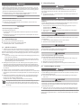 6
6
-
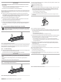 7
7
-
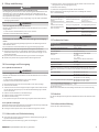 8
8
-
 9
9
-
 10
10
-
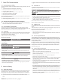 11
11
-
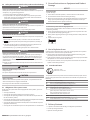 12
12
-
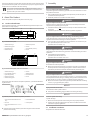 13
13
-
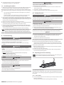 14
14
-
 15
15
-
 16
16
-
 17
17
-
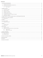 18
18
-
 19
19
-
 20
20
-
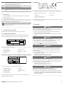 21
21
-
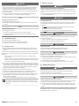 22
22
-
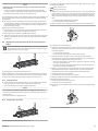 23
23
-
 24
24
-
 25
25
-
 26
26
-
 27
27
-
 28
28
-
 29
29
-
 30
30
-
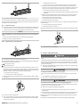 31
31
-
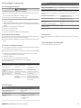 32
32
-
 33
33
-
 34
34
-
 35
35
-
 36
36
-
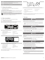 37
37
-
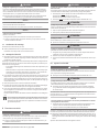 38
38
-
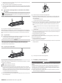 39
39
-
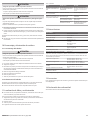 40
40
-
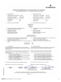 41
41
-
 42
42
-
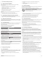 43
43
-
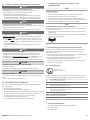 44
44
-
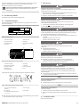 45
45
-
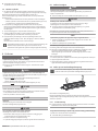 46
46
-
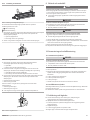 47
47
-
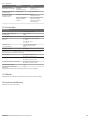 48
48
-
 49
49
-
 50
50


AVENTICS Pneumatic piston rod cylinders (ATEX) Mode d'emploi
- Taper
- Mode d'emploi
dans d''autres langues
- italiano: AVENTICS Pneumatic piston rod cylinders (ATEX) Istruzioni per l'uso
- English: AVENTICS Pneumatic piston rod cylinders (ATEX) Operating instructions
- español: AVENTICS Pneumatic piston rod cylinders (ATEX) Instrucciones de operación
- Deutsch: AVENTICS Pneumatic piston rod cylinders (ATEX) Bedienungsanleitung
- svenska: AVENTICS Pneumatic piston rod cylinders (ATEX) Bruksanvisningar
Documents connexes
-
AVENTICS Pneumatic piston rod cylinders (ATEX) Le manuel du propriétaire
-
-
-
-
-
-
-
-
-
Autres documents
-
Emerson AVENTICS Manuel utilisateur
-
Emerson CO1 Manuel utilisateur
-
-
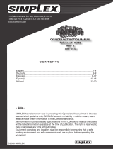 Simplex Cylinders - 86183 B Manuel utilisateur
-
 Simplex RDA1010 Manuel utilisateur
-
GYS PNEUMATIC ALUMINIUM DUST EXTRACTOR (ATEX) Le manuel du propriétaire
-
FANATEC CSL Elite Wheel Base Mode d'emploi
-
sauter 297800 Assembly Instructions
-
 Debem Equaflux 100 Instructions For Use And Maintenance Manual
-
Siemens 8WD44 Manuel utilisateur


