Kichler Lighting 49644OZ Manuel utilisateur
- Taper
- Manuel utilisateur

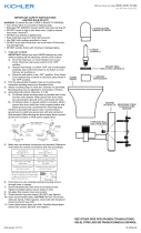
1) TURN OFF POWER.
a) IMPORTANT: Before you start, NEVER attempt any work
without shutting off the electricity until the work is done.
b) Go to the main fuse, or circuit breaker, box in your home.
Place the main power switch in the “OFF” position.
c) Unscrew the fuse(s), or switch “OFF” the circuit breaker
switch(s), that control the power to the fixture or room that
you are working on.
d) Place the wall switch in the “OFF” position. If the fixture to
be replaced has a switch or pull chain, place those in the
“OFF” position.
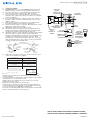
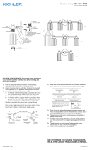
2) Find the appropriate threaded holes on mounting strap.
Assemble mounting screws into threaded holes.
3) Attach mounting strap to outlet box. Mounting strap can be
adjusted to suit position of fixture.
4) Grounding instructions: (See Illus. A or B)
A) On fixtures where mounting strap is provided with a hole
and two raise dimples. Wrap ground wire from outlet box
around green ground screw, and thread into hole.
B) On fixtures where a cupped washer is provided. Put ground
wire from outlet box under cupped washer and green
ground screw and thread screw into hole in mounting strap.
If fixture is provided with ground wire. Connect fixture
ground wire to outlet box ground wire with wire connector
after following the above steps. Never connect ground wire
to black or white power supply wires.
5) Make wire connections. Reference chart below for correct
connections and wire accordingly.
6) Push fixture to wall, carefully passing mounting screws
through holes. Be sure not to pinch wires between wall and
canopy of fixture.
7) Screw threaded lock-up knobs onto mounting screws. Tighten
lock-up knobs to secure fixture to wall.
8) Raise glass up to fixture. Pass hole in glass over socket.
9) Slip spacer over socket.
10) Insert socket ring inside socket ring tool.
11) Raise the socket ring tool with socket ring attached up to
socket and thread socket ring onto socket. Tighten socket ring
to secure glass in place. (DO NOT over tighten.)
12) Insert recommended bulb, align and insert pins on bulb with
holes in socket and twist to secure in place.
Date Issued: 03/17/16 IS-49644-US
GREEN GROUND
SCREW
CUPPED
WASHER
A
B
OUTLET BOX
GROUND
FIXTURE
GROUND
DIMPLES
WIRE CONNECTOR
(NOT PROVIDED)
OUTLET BOX
GROUND
GREEN GROUND
SCREW
FIXTURE
GROUND
Connect Black or
Red Supply Wire to:
Connect
White Supply Wire to:
Black White
*Parallel cord (round & smooth) *Parallel cord (square & ridged)
Clear, Brown, Gold or Black
without tracer
Clear, Brown, Gold or Black
with tracer
Insulated wire (other than green)
with copper conductor
Insulated wire (other than green)
with silver conductor
*Note: When parallel wires (SPT I & SPT II)
are used. The neutral wire is square shaped
or ridged and the other wire will be round in
shape or smooth (see illus.)
Neutral Wire
SEE OTHER SIDE FOR SPANISH TRANSLATIONS.
VEA EL OTRO LADO DE TRADUCCIONES AL ESPAÑOL.
We’re here to help 866-558-5706
Hrs: M-F 9am to 5pm EST
FIXTURE
ARTIFACTO
LOCK-UP
KNOBS
PERILLA DE
BLOQUED
MOUNTING
STRAP
ABRAZADERA DE
MONTAJE
GLASS
VIDRIO
SOCKET RING
ANILLO DEL
CASQUILLO
SOCKET
RING TOOL
HERRA-
MIENTA DEL
ANILLO DEL
CASQUILLO
BULB
(NOT INCLUDED)
BOMBILLA
(NON INCLUS)
SPACER
ESPACIADOR
OUTLET
BOX
MISE À LA
TERRE

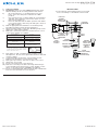
1) APAGUE LA ALIMENTACIÓN DE ENERGÍA ELÉCTRICA.
a) IMPORTANTE: Antes de comenzar, NUNCA trate de tra
bajar sin antes desconectar la corriente hasta que el trabajo
se termine.
b) Vaya a la caja principal de fusibles o interruptor automático
de su casa. Coloque el interruptor de la corriente principal en
posición de apagado “OFF”.
c) Desenrosque el (los) fusible(s), o coloque el interruptor o
interruptores automáticos en posición de apagado “OFF”,
que controla(n) la corriente hacia el artefacto o habitación
donde está trabajando.
d) Coloque el interruptor de pared en posición de apagado
“OFF”. Si el artefacto que se va a reemplazar tiene un
interruptor o cadena que se jala, colóquelos en la posición
de apagado “OFF”.
2) Encuentre los agujeros roscados apropiados sobre la correa
de montaje. Ensamble los tornillos de montaje en los agujeros
roscados.
3) Fije la correa de montaje a la caja de salida. La correa de
montaje puede ser ajustada para adaptarse a la posición del
artefacto.
4) Instrucciones para poner a tierra: (Ver ilustraciones A o B)
A) En artefactos donde se suministra la abrazadera de mon
taje con un agujero y dos depresiones onduladas. Envuelva el
conductor de tierra de la caja de salida alrededor del tornillo
de tierra verde y atornille en el agujero.
B) En artefactos donde se suministra una arandela cóncava.
Fije el conductor de tierra de la caja de salida debajo de la
arandela cóncava y el tornillo de tierra verde y enrosque en la
abrazadera de montaje.
Si se suministra el artefacto con conductor de tierra. Conecte el
conductor de tierra del artefacto al conductor de tierra de la caja
de salida con conector de tierra después de seguir los pasos
anteriores. Nunca conecte el conductor de tierra a los cables de
alimentación eléctrica negros o blancos.
5) Haga las conexiones de cables. Consulte la gráfica de abajo
con la conexiones correctas y haga el cableado que correspon-
de.
6) Empuje el artefacto a la pared, pasando cuidadosamente los
tornillos de montaje a través de los agujeros. Asegúrese de no
pellizcar los alambres entre la pared y el escudete del artefacto.
7) Enrosque las perillas de sujeción en los tornillos de montaje.
Apriete las perillas de sujeción para asegurar el artefacto a la
pared.
8) Suba el vidrio hacia el artefacto. Pase el agujero en el vidrio
sobre el casquillo.
9) Deslice el espaciador sobre el casquillo.
10) Inserte el anillo del casquillo dentro de la herramienta del
anillo del casquillo.
11) Suba la herramienta del anillo del casquillo con el anillo del
casquillo adjunto hasta el casquillo y enrosque el anillo del cas-
quillo en el casquillo. Apriete el anillo del casquillo para asegurar
el vidrio en su lugar. (NO apriete demasiado).
12) Inserte la bombilla o foco recomendado, alinee e inserte las
patas de la bombilla en los agujeros en el casquillo y gire para
asegurar en su lugar.
Date Issued: 03/17/16 IS-49644-US
Conectar el alambre de
suministro negro o rojo al
Conectar el alambre de
suministro blanco al
Negro Blanco
*Cordon paralelo (redondo y liso)
*Cordon paralelo (cuadrado y estriado)
Claro, marrón, amarillio o negro
sin hebra identificadora
Claro, marrón, amarillio o negro
con hebra identificadora
Alambre aislado (diferente del verde)
con conductor de cobre
Alambre aislado (diferente del
verde) con conductor de plata
*Nota: Cuando se utiliza alambre paralelo
(SPT I y SPT II). El alambre neutro es de forma
cuadrada o estriada y el otro alambre será de
forma redonda o lisa. (Vea la ilustracíón).
Hilo Neutral
ARANDELA
CONCAVA
A
B
TIERRA DE LA
CAJA DE SALIDA
TORNILLO DE TIERRA,
VERDE
DEPRESIONES
TIERRA
ARTEFACTO
CONECTOR DE ALAMBRE
(NO SE PROVEE)
TIERRA DE LA
CAJA DE SALIDA
TORNILLO DE TIERRA,
VERDE
TIERRA
ARTEFACTO
SEE OTHER SIDE FOR ENGLISH TRANSLATIONS.
VEA EL OTRO LADO DE TRADUCCIONES AL INGLÉS.
We’re here to help 866-558-5706
Hrs: M-F 9am to 5pm EST
FIXTURE
ARTIFACTO
LOCK-UP
KNOBS
PERILLA DE
BLOQUED
MOUNTING
STRAP
ABRAZADERA DE
MONTAJE
GLASS
VIDRIO
SOCKET RING
ANILLO DEL
CASQUILLO
SOCKET
RING TOOL
HERRA-
MIENTA DEL
ANILLO DEL
CASQUILLO
BULB
(NOT INCLUDED)
BOMBILLA
(NON INCLUS)
SPACER
ESPACIADOR
OUTLET
BOX
MISE À LA
TERRE

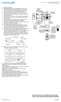
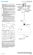
1) TURN OFF POWER.
a) IMPORTANT: Before you start, NEVER attempt any work
without shutting off the electricity until the work is done.
b) Go to the main fuse, or circuit breaker, box in your
home. Place the main power switch in the “OFF”
position.
c) Unscrew the fuse(s), or switch “OFF” the circuit breaker
switch(s), that control the power to the fixture or room
that you are working on.
d) Place the wall switch in the “OFF” position. If the fixture
to be replaced has a switch or pull chain, place those in
the “OFF” position.
2) Find the appropriate threaded holes on mounting strap.
Assemble mounting screws into threaded holes.
3) Attach mounting strap to outlet box. Mounting strap can be
adjusted to suit position of fixture.
4) Make wire connections. Reference chart below for correct
connections and wire accordingly.
5) Push fixture to wall, carefully passing mounting screws
through holes. Be sure not to pinch wires between wall and
canopy of fixture.
6) Screw threaded lock-up knobs onto mounting screws.
Tighten lock-up knobs to secure fixture to wall.
7) Raise glass up to fixture. Pass hole in glass over socket.
8) Slip spacer over socket.
9) Insert socket ring inside socket ring tool.
10) Raise the socket ring tool with socket ring attached up to
socket and thread socket ring onto socket. Tighten socket
ring to secure glass in place. (DO NOT over tighten.)
11) Insert recommended bulb, align and insert pins on bulb with
holes in socket and twist to secure in place.
Connect Black or
Red Supply Wire to:
Connect
White Supply Wire to:
Black White
*Parallel cord (round & smooth) *Parallel cord (square & ridged)
Clear, Brown, Gold or Black
without tracer
Clear, Brown, Gold or Black
with tracer
Insulated wire (other than green)
with copper conductor
Insulated wire (other than green)
with silver conductor
*Note: When parallel wires (SPT I & SPT II)
are used. The neutral wire is square shaped
or ridged and the other wire will be round in
shape or smooth (see illus.)
Neutral Wire
Date Issued: 03/17/16
IS-49644-CB-CB
INSTRUCTIONS
For Assembling and Installing Fixtures in Canada
Pour L’assemblage et L’installation Au Canada
We’re here to help 866-558-5706
Hrs: M-F 9am to 5pm EST
FIXTURE
LUMINAIRE
LOCK-UP
KNOBS
BOULES DE
BLOCAGE
MOUNTING
STRAP
ETRIER DE
MONTAGE
GLASS
VERRE
SOCKET RING
ANNEAU DE
DOUILLE
SOCKET
RING TOOL
OUITL DE
L’ZANNEAU
DE LA
DOUILLE
BULB
(NOT INCLUDED)
AMPOULE
(PAS INCLUSE)
SPACER
ENTRETOISE
OUTLET
BOX
BOÎTE Â
PRISES

Connect Black or
Red Supply Wire to:
Connect
White Supply Wire to:
Black White
*Parallel cord (round & smooth) *Parallel cord (square & ridged)
Clear, Brown, Gold or Black
without tracer
Clear, Brown, Gold or Black
with tracer
Insulated wire (other than green)
with copper conductor
Insulated wire (other than green)
with silver conductor
*Note: When parallel wires (SPT I & SPT II)
are used. The neutral wire is square shaped
or ridged and the other wire will be round in
shape or smooth (see illus.)
Neutral Wire
Date Issued: 03/17/16
IS-49644-CB-CB
INSTRUCTIONS
For Assembling and Installing Fixtures in Canada
Pour L’assemblage et L’installation Au Canada
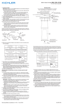
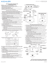
INSTRUCTIONS DE MONTAGE DE LUMINAIRE À L’EXTÉRIEUR
ET/OU DANS DES LIEUX HUMIDES.
1) La surface de montage doit être propre, sèche, plate et de
0,6 cm plus épaisse que le cache sur tous les côtés. Tout
écart entre la surface de montage et le cache dépassant de
0,5 cm doit être rectifié selon les besoins.
2) À l’aide de matériaux d’étanchéité à la silicone, calfeutrer
bien autour où l’arrière du cache entre en contact avec le
mur pour empêcher l’eau de passer dans la boîte de raccor
dement.
We’re here to help 866-558-5706
Hrs: M-F 9am to 5pm EST
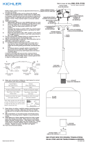
FIXTURE
LUMINAIRE
LOCK-UP
KNOBS
BOULES DE
BLOCAGE
MOUNTING
STRAP
ETRIER DE
MONTAGE
GLASS
VERRE
SOCKET RING
ANNEAU DE
DOUILLE
SOCKET
RING TOOL
OUITL DE
L’ZANNEAU
DE LA
DOUILLE
BULB
(NOT INCLUDED)
AMPOULE
(PAS INCLUSE)
SPACER
ENTRETOISE
OUTLET
BOX
BOÎTE Â
PRISES
1)COUPER LE COURANT.
a) IMPORTANT: TOUJOURS couper le courant avant de com
mencer le travail.
b) Localiser le coffret à fusibles ou le disjoncteur du domicile.
Mettre l’interrupteur principal en position d’Arrêt.
c) Dévisser le ou les fusibles (ou mettre le disjoncteur sur Arrêt)
qui contrôlent l’alimentation vers le luminaire ou la pièce
dans laquelle le travail est effectué.
d) Mettre l’interrupteur mural en position d’Arrêt. Si le luminaire
à remplacer est doté d’un interrupteur ou d’une chaîne con
nectée à l‘interrupteur, placer ces éléments en position
d’Arrêt.
2)Trouver les trous filetés appropriés sur l’étrier de montage.
Visser les vis de montage dans les trous taraudés.
3) Fixer l’étrier de montage sur la boîte à prises. L’étrier de mon-
tage peut être réglé en fonction de la position du luminaire.
4) Établir les branchements des fils. Se reporter au tableau ci-
dessous pour les connexions appropriées et acheminer les fils
selon les instructions.
5) Pousser le luminaire vers le mur, en passant soigneusement
les vis de montage par les trous. Ne pas pincer les fils entre le
mur et le cache du luminaire.
6) Visser les boules de blocage filetées sur les vis de fixation.
Serrer les boules de blocage pour fixer le luminaire au plafond.
7) Soulever le verre jusqu’au luminaire. Passer le trou dans le
verre sur la douille.
8) Glisser l’entretoise sur la douille.
9) Placer l’anneau de douille dans l’outil d’anneau de la douille.
10) Soulever l’outil d’anneau de la douille avec l’anneau de la
douille attaché à la douille et visser l’anneau de la douille sur la
douille. Serrer l’anneau de la douille pour fixer le verre. (NE PAS
serrer avec excès).
11) Insérer l’ampoule recommandée, aligner des broches sur
l’ampoule avec les trous dans la douille, insérer et tourner pour
fixer.
-
 1
1
-
 2
2
-
 3
3
-
 4
4


Kichler Lighting 49644OZ Manuel utilisateur
- Taper
- Manuel utilisateur
dans d''autres langues
Documents connexes
-
Kichler 45581CH Manuel utilisateur
-
 Kichler Lighting 49643OZ Manuel utilisateur
-
 Kichler Lighting 49723WZC Manuel utilisateur
-
 Kichler Lighting 45033DAG Manuel utilisateur
-
 Kichler Lighting 43359CH Manuel utilisateur
-
 Kichler Lighting 44003NI Manuel utilisateur
-
 Kichler Lighting 43354CH Manuel utilisateur
-
 Kichler Lighting 45905CH Manuel utilisateur
-
-
 Kichler Lighting 43152AP Manuel utilisateur


