ROBBE RO-Control NAVY Pro 120 A Mode d'emploi
- Catégorie
- Jouets
- Taper
- Mode d'emploi
Ce manuel convient également à

PRO
ro-navy
ro-navy
PRO
Operating Manual
?

Operating Manual
RO-Control NAVY Pro Series
No.8725
No.8726
Operating Manual
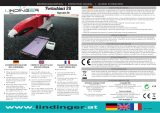
RO-CONTROL Navy Pro
120/160A
Brushless Electronic Speed
Controller
Art.-Nr.: 8725 Ro-Control Navy Pro 120
Art.-Nr.: 8726 Ro-Control Navy Pro 160
Dear customer, we are pleased that you have chosen a RO-Control Navy speed controller for
brushless motors from our range. This gives you a particularly powerful controller for controlling
your rc-boats engine.
Despite the relatively simple operation of these controllers, their use requires some knowledge
from you. These instructions will help you to familiarize yourself quickly with the possibilities of the
speed controller. To achieve this goal safely and quickly, you should read these operating
instructions carefully before commissioning the controller. The safety and warning notices are of
particular importance.
Brushless motors can be very dangerous. Any improper use can
cause personal injury and destroy the controller and the devices
connected to it. We strongly recommend that you read these
operating instructions completely before use.
Since we have no control over the use, installation or maintenance of the controller, we accept no
liability for this product for any damage or loss resulting from the use of the product.
We also accept no responsibility for damage or loss caused by unauthorized changes to our
product.
Remote-controlled models are not toys and may only be used by young people under 14 years of
age under the constant supervision of adults who are familiar with the construction, operation,
material and possible dangers. Construction, commissioning and operation of remote-controlled
models are dangerous and are the full responsibility of the operator. We expressly point out these
risks and accept no liability. Careful, well-considered handling during operation protects against
personal injury and property damage. Perform maintenance and inspections of your models and
electronic devices at short, regular intervals. Check regularly that all fastenings are securely
fastened.
The controllers are only intended for use in battery- or battery-operated, remote-controlled
models. Any other operation is not permitted. Please note that despite many safety features, an
accidentally starting electric motor, e.g. due to a defect of the controller, has considerable risk
potential and can result in considerable injuries. We cannot check the handling of the controller
and reject any claim for damages due to failure, faulty operation or malfunction. We assume no
liability for personal injury, property damage and their consequences arising from our delivery or
work. Never operate a damaged regulator, e.g. due to exposure to water or mechanical
deformation, a crash or similar.
01. Introduction
02. Safety and Warnings

Operating Manual
RO-Control NAVY Pro Series
No.8725
No.8726
Operating Manual
RO-CONTROL Navy Pro
120/160A
Brushless Electronic Speed
Controller
Art.-Nr.: 8725 Ro-Control Navy Pro 120
Art.-Nr.: 8726 Ro-Control Navy Pro 160
Dear customer, we are pleased that you have chosen a RO-Control Navy speed controller for
brushless motors from our range. This gives you a particularly powerful controller for controlling
your rc-boats engine.
Despite the relatively simple operation of these controllers, their use requires some knowledge
from you. These instructions will help you to familiarize yourself quickly with the possibilities of the
speed controller. To achieve this goal safely and quickly, you should read these operating
instructions carefully before commissioning the controller. The safety and warning notices are of
particular importance.
Brushless motors can be very dangerous. Any improper use can
cause personal injury and destroy the controller and the devices
connected to it. We strongly recommend that you read these
operating instructions completely before use.
Since we have no control over the use, installation or maintenance of the controller, we accept no
liability for this product for any damage or loss resulting from the use of the product.
We also accept no responsibility for damage or loss caused by unauthorized changes to our
product.
Remote-controlled models are not toys and may only be used by young people under 14 years of
age under the constant supervision of adults who are familiar with the construction, operation,
material and possible dangers. Construction, commissioning and operation of remote-controlled
models are dangerous and are the full responsibility of the operator. We expressly point out these
risks and accept no liability. Careful, well-considered handling during operation protects against
personal injury and property damage. Perform maintenance and inspections of your models and
electronic devices at short, regular intervals. Check regularly that all fastenings are securely
fastened.
The controllers are only intended for use in battery- or battery-operated, remote-controlled
models. Any other operation is not permitted. Please note that despite many safety features, an
accidentally starting electric motor, e.g. due to a defect of the controller, has considerable risk
potential and can result in considerable injuries. We cannot check the handling of the controller
and reject any claim for damages due to failure, faulty operation or malfunction. We assume no
liability for personal injury, property damage and their consequences arising from our delivery or
work. Never operate a damaged regulator, e.g. due to exposure to water or mechanical
deformation, a crash or similar.
01. Introduction
02. Safety and Warnings
Operating Manual
RO-Control NAVY Pro Series
No.8725
No.8726
Page
2
Make sure that you do not reverse the polarity of the battery, that you avoid short circuits, that the
drive motor is effectively suppressed and that the air can circulate freely. Use plug systems that
are protected against polarity reversal. All cables and connections should be well insulated. The
regulator must not come into contact with grease or oil. Only use the connectors, original parts and
accessories recommended by us. Always set the throttle to "Stop" before switching on the
transmitter.
In addition, it is imperative that you observe the following notes:
• Make sure that all cables and connections are well insulated before connecting the controller to
other devices, as a short circuit can damage the controller.
• Ensure that all equipment is properly connected, poor connections may cause you to lose
control of your model ship and cause other unforeseen problems, personal injury, property
damage or destruction of the controller.
• Please use a soldering iron with a power of at least 60 W to solder all input and output lines.
• Stop the controller if the heat sink temperature exceeds 90 °C. Otherwise the controller and / or
the motor will be damaged. We recommend activating the thermal protection (ESC Thermal
Protection) which automatically stops operation at a value of 105 °C inside the controller.
• Never try to operate two brushless motors with only one controller, otherwise the controller will
fail.
• Always keep the propeller away from your body and other objects, as they can be very
dangerous.
• Protect the speed controller from vibrations, dust, moisture and mechanical stress!
• Always connect the drive battery to the controller just before starting the model. After you have
landed/develed, disconnect immediately.
• The controller is equipped with a tarnish protection. Nevertheless, for safety reasons, be very
careful and cautious when plugging the battery into the controller to prevent personal injury.
• Even if the receiving system is switched off, but the battery is still connected to the controller,
there is a fundamental risk potential.
• Make absolutely sure that the controller is always operated within the values of the technical
data. Overloading can lead to damage, resulting in great dangers.
• Always follow the instructions for connecting and installing the controller.
• High currents cause the cables to heat up, which can cause fire or burns to the skin. Lay the
cabling accordingly and proceed very carefully.
• Be sure to follow the warnings of the manufacturer of the motor, battery and model you are
using.
• The controller must never be connected to the 230V AC mains.
• When operating a rc-boat, you must comply with all safety regulations, so as not to endanger
themselves and others.
After use, please remove all batteries and dispose of them separately. Hand in old
electrically operated equipment free of charge at the municipalities' collection points for
electrical waste. The remaining parts belong in the household waste. Thank you for
your help!

Operating Manual
RO-Control NAVY Pro Series
No.8725
No.8726
Page
3
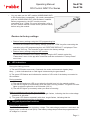
• Lightweight design and therefore perfectly suited for competitive models
• No additional precautions against splash water are necessary, the regulator, however, is
excellently protected by a nano coating, it can be immersed in water.
Note: However, it is necessary to dry all plugs well after use, if they have been in contact with
water, so that the plugs do not oxidize.
• Integrated pulsed BEC with switchable voltage of 6 V / 7.4 V and a load of 4.0 A (peak load 8.0
A), for use with powerful HV servos.
• Patented thermally conductive copper bars combined with water cooling and MOSFETs with
extremely low internal resistance, thus high reliability and high efficiency of the controller and
safe use even under short-term overloads
• Innovative firmware guarantees the user excellent control over the model in various competitive
scenarios
• Innovative turbo acceleration function (turbo timing) possible, the engine suddenly delivers the
absolute maximum power for acceleration and quickly leaves competitors behind during the
race.
• Two different modes adjustable: forward, forward and reverse for universal applications
• Several built-in safety precautions: Undervoltage cut-off, overheating protection, protection
against loss of input signal
• Eight different timing levels programmable, thus compatible with most brushless motors
• Convenient programming via optional LCD programming box possible
• Firmware update possible via the optional LCD programming box
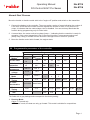
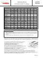
RO-Control Navy Pro 120 A
RO-Control Navy Pro 160 A
Rated current
120 A 160 A
Peak current
760 A 1050 A
BEC Type
clocked BEC, reversible 6 V / 7,4 V encumbrance 4,0 A
LiPo Cells
2 – 6S LiPo battery
Water cooling
inner diameter 2 mm, exterior-
diameter 5,5 mm
inner diameter 3 mm, exterior-
diameter 5,5 mm
Dimension
96,6 x 37,9 x 10,3 mm 108,5 x 51,5 x 14,4 mm
Weight
87,5 g 127 g
Boat Applicable
Mono 1 and other racing boats
(Length to 100 cm)
Mono 2 and other racing boats
(length to 120 cm)
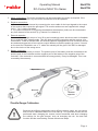
1. Water cooling: (suitable silicone hose must be procured optionally)
The silicone hose for cooling water supply must be pushed onto the aluminium water cooling
tube (outer diameter = 5.5 mm) mounted at the factory.
03
.
Features
04. Technical Specifications
05. Commissioning a new controller
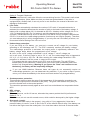
Connections

Moteur
Récepteur
Accu
Condensateur
Externe
Operating Manual
RO-Control NAVY Pro Series
No.8725
No.8726
Page
3
• Lightweight design and therefore perfectly suited for competitive models
• No additional precautions against splash water are necessary, the regulator, however, is
excellently protected by a nano coating, it can be immersed in water.
Note: However, it is necessary to dry all plugs well after use, if they have been in contact with
water, so that the plugs do not oxidize.
• Integrated pulsed BEC with switchable voltage of 6 V / 7.4 V and a load of 4.0 A (peak load 8.0
A), for use with powerful HV servos.
• Patented thermally conductive copper bars combined with water cooling and MOSFETs with
extremely low internal resistance, thus high reliability and high efficiency of the controller and
safe use even under short-term overloads
• Innovative firmware guarantees the user excellent control over the model in various competitive
scenarios
• Innovative turbo acceleration function (turbo timing) possible, the engine suddenly delivers the
absolute maximum power for acceleration and quickly leaves competitors behind during the
race.
• Two different modes adjustable: forward, forward and reverse for universal applications
• Several built-in safety precautions: Undervoltage cut-off, overheating protection, protection
against loss of input signal
• Eight different timing levels programmable, thus compatible with most brushless motors
• Convenient programming via optional LCD programming box possible
• Firmware update possible via the optional LCD programming box
RO-Control Navy Pro 120 A
R
O-Control Navy Pro 160 A
Rated current
120 A 160 A
Peak current
760 A 1050 A
BEC Type
clocked BEC, reversible 6 V / 7,4 V encumbrance 4,0 A
LiPo Cells
2 – 6S LiPo battery
Water cooling
inner diameter 2 mm, exterior-
diameter 5,5 mm
inner diameter 3 mm, exterior-
diameter 5,5 mm
Dimension
96,6 x 37,9 x 10,3 mm 108,5 x 51,5 x 14,4 mm
Weight
87,5 g 127 g
Boat Applicable
Mono 1 and other racing boats
(Length to 100 cm)
Mono 2 and other racing boats
(length to 120 cm)
1. Water cooling: (suitable silicone hose must be procured optionally)
The silicone hose for cooling water supply must be pushed onto the aluminium water cooling
tube (outer diameter = 5.5 mm) mounted at the factory.
03
.
Features
04. Technical Specifications
05. Commissioning a new controller
Connections
Page
4
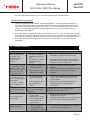
2. Motor connections: The motor connections can be connected to the motor as required. If the
motor runs upside down, any two motor connections must be replaced
3. Receiver connection:
1. Connect the throttle channel by connecting the servo cable for the input signals to the output
of the receiver that outputs the gas signal. The receiver and servos are supplied with voltage
(6.0 V / 7.4 V) via the red cable.
2. The yellow connection for triggering the additional acceleration (turbo) can be connected to
any free channel of the receiver (e.g. channel 3 or channel 4).
4. External capacitor:
Servos with a very high torque of over 20 kg are increasingly used, which can result in feedback
due to relatively high voltage peaks. This can destroy both the controller and the receiver. We
recommend: To be on the safe side, an external capacitor equipped with a JR connector should
be used and plugged into a free receiver output. Make sure that the polarity is correct. If no slot
on the receiver is available, use a "Y" cable. No warranty will be given if the ESC is damaged
due to the choice of the wrong servo.
5. Battery connection:
Make sure that the polarity is correct. The positive pole of the battery must be connected to the
positive pole of the controller and the negative pole of the battery to the negative pole of the
controller. If the controller is connected with the wrong polarity, it may be damaged. This is not
covered by the warranty!
Because the different transmitters have different sensor paths, the gas control
stick must be calibrated before the first start-up. This procedure must also be
performed when changing the remote control transmitter and when changing
the settings for the gas channel, such as changing the trim, the dual rate
function and the travel setting. Please follow these steps.
Operating Manual
RO-Control NAVY Pro Series
No.8725
No.8726
Throttle Range Calibration
Receiver
Speed Controller
Battery
external
capacitor

Page
5
1. Switch on the transmitter and controller, set the parameters for the gas channel such as
Dual rate or the travel setting to 100 %. Set the throttle trim to "0". For transmitters without LC
display, set the encoder to maximum and the mechanical trim to the center. For Futaba
transmitters set the direction to "Reverse", for other transmitters it must remain set to
"Normal". We recommend activating a Fail Safe function to ensure that your ship stops if
there is no valid input signal.
Notice: If the transmitter is equipped with an ABS function, be sure to disable it. It hinders
the procedure for the calibration of the gas control stick or makes the procedure impossible.
2. Calibrate the throttle on a pistol grip transmitter:
Pull the throttle back to the full throttle position and hold it in
this position, then connect the battery to the regulator, 2 sec.
later the engine emits two short tones (beep, beep), the full
throttle position has been accepted.
Move the throttle to the neutral position, a long tone
(beep----) is emitted, i.e. calibration is complete.
Notice:
While the acoustic signal is being emitted,
the red LED lights up simultaneously.
3. Calibrate one transmitter throttle lever with joysticks:
Pull the throttle stick into the front position into full throttle
position, then connect the battery to the regulator, 2 sec. later
the engine emits two short tones (beep-, beep-), the full
throttle position has been accepted.
If you want to set the throttle range to the "half stick travel",
move the throttle lever to the new position. If you want to use
the full stick travel, move the throttle stick to the lower
position. A long tone (beep----) is emitted, i.e. calibration is
complete.
Notice:
While the acoustic signal is being output,
the red LED lights up simultaneously.
Operating Manual
RO-Control NAVY Pro Series
No.8725
No.8726
Page
6
Move the throttle or throttle control stick to the "engine off" position and switch on the transmitter.
1. Connect the battery to the controller. The motor emits a series of tones indicating the number of
LiPo cells. Check that the number of tones matches the number of cells. If only one tone is
output, it indicates that the undervoltage cutoff is disabled. You can and may deactivate this
function during programming only for nickel cells.
2. A second later, the motor emits a long beep (beep----) indicating that the controller is ready for
operation. If the control transmitter is not in the correct position, a permanent warning tone
(beep, beep, beep) is emitted until the encoder is brought into the "motor off" position.
3. Move the throttle control stick forward, the engine starts.
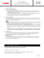
Programmable parameters
1 2 3 4 5 6 7 8
1. Running
Modus
forward
only
forward &
backwards
2. LiPo Cells
automa-
tic
2S 3S 4S 5S 6S
3. Undervoltage
protection
turned-
off
2,8 V/
cell
3,0 V/
cell
3,2V /
cell
3,4V /
cell
4. Over
temperature
protection
105
o
C 125
o
C
deact.
5. BEC
voltage
6,0 V 7,4 V
6. Starter
Mode
Level 1 Level 2
Level
3
Level
4
Level
5
7. General
Timing
0,00
o
3,75
o
7,50
o
11,25
o
15,00
o
18,25
o
22,50
o
26,25
o
8. Turbo
Acceleration
activated deactivated
9. Turbo
Timing
0,00
o
3,75
o
7,50
o
11,25
o
15,00
o
18,75
o
22,50
o
26,25
o
10. PWM
rate
6 kHz 8 kHz
12
kHz
16
kHz
The fields with a grey background correspond to the factory setting
1. Running Mode:
Option 1: Forward only
In "Forward" mode, the boat can only go forward. This mode is suitable for competitions.
06. Programmable parameters of the controller
Operating Manual
RO-Control NAVY Pro Series
No.8725
No.8726
Normal Start Process

Page
7
Option 2: Forward / Backward
The "Forward/Reverse" mode also offers the reverse driving function. This mode is well suited
for most applications. (Note: Make sure that your boat can go backwards. If the drive is
equipped with a flexible shaft, it can only move in one direction, the reversal of direction can
damage a flexible shaft.
2. LiPo Cells:
The controller automatically calculates the number of LiPo cells. If automatic detection is
activated, the controller determines the number of cells on the basis of the battery voltage. A
battery with a voltage below 8.8 V is detected as 2S LiPo. A battery with a voltage of 8.8 V to
13.2 V is identified as 3S LiPo. If a battery is not fully charged when connected to the
controller, miscalculations may occur so that a 6S LiPo that is not fully charged is identified as
5S LiPo. As a result, the undervoltage protection function may not function properly. Therefore,
you must always plug in a fully charged battery. If you only use one LiPo battery at a time, we
recommend manual setting of the LiPo cell count.
3. Undervoltage protection:
If you are using a LiPo battery, you must set a correct cut-off voltage for your battery
according to the discharge rate "C". The ESC constantly monitors the battery voltage.
The undervoltage protection is activated, the output power is significantly reduced if the
battery voltage drops below the programmed cut-off voltage.
A: How is the cut-off voltage calculated? cut-off voltage = cut-off voltage per
cell x cell count. If the limit value is set to 3.2 V / cell, the undervoltage drop is triggered at
9.6 V (3 x 3.2 V) with a 3S LiPo. B: After entering the undervoltage threshold: If the
protection is activated, half the power is output at the output.
This means that the output power is only 50% even at full throttle. The red LED then
flashes slowly at the same time. Please return your boat to land immediately and insert
another fully charged battery. Warning! If you ignore the "Note" and continue to use
the battery, the battery will be irreparably damaged.
C:
If you use NIMH batteries: Because these cell types do not necessarily require an
undervoltage protection, you can deactivate the protection. If you notice a drop in power,
return your rc-boat immediately to the shore and insert another fully charged battery.
4. Overtemperature protection:
This protection does not stop the motor if the temperature of the controller exceeds the set
value, but the output power is reduced to half (50%). The green LED flashes every time you
move the throttle lever to the neutral position.
The controller operates normally again as soon as it has cooled down to a temperature below
80°C.
5. BEC voltage
Option 1: 6.0 V
For normal servos, not for HV servos, otherwise they cannot provide their full performance
Option 2: 7.4 V
For HV servos, do not use with normal servos, which could be destroyed by the higher voltage
6. Start mode / punch:
You can set the start mode in the ranges 1 (very soft) to 5 (very aggressive). Note that a
powerful battery is used in "Level 4" and "Level 5",so the tension doesn't drop. If the battery can
not deliver the high current the model jerks. You must then reduce the level of the start mode.
Operating Manual
RO-Control NAVY Pro Series
No.8725
No.8726
Page
8
7. Timing / General Timing:
This function has three aspects:
• The controller can be configured for operation with different motors. The default setting of
15 degrees is suitable for many motors, but special motors require different values. Set the
optimal timing level for your engine.
• Fine-tune the output power of the motor. The higher the timing is set, the higher the engine
speed and power of the engine, but more electrical energy is consumed.
• Optimum adjustment of the motor to the most efficient operation
8. Turbo acceleration:
When the turbo acceleration is triggered, the controller immediately goes to the set value of the
turbo timing stage and thus provides greater power. This function can be used on longer straight
stretches on the water, outside curves
Note 1:
• For the additional acceleration you need another channel (channel 3 or 4), connect the
additional connection cable to the corresponding receiver output. The servo travel on this
channel must be set to at least 80%, use the normal setting of 100%.
• With a pistol grip transmitter, channel 3 or 4 is usually implemented by a key, pressing the
key activates the turbo acceleration. With a normal transmitter, channel 3 or 4 is usually
implemented by a switch, and turbo acceleration is activated or deactivated by pressing a
switch.
• If the general timing is set higher than the turbo timing (example: normal timing at 22.5
degrees and turbo timing at 15 degrees) the turbo acceleration has no effect. Therefore,
make sure that the turbo timing value is set higher than the normal timing value.
9. Turbo Timing:
The value can be set between 0 and 26.25 degrees, the value becomes effective as soon as
the turbo acceleration is activated. When turbo acceleration is enabled, the ESC sets the
appropriate turbo timing after receiving a signal for turbo acceleration.
10. PWM frequency:
Increasing the PWM frequency can cause the motor to run smoother, smoother and the noise
to decrease, but the regulator will heat up more. If the motor runs smoothly, we recommend
selecting the default setting (8 KHz).
Programming is carried out in four steps.
Activate programming mode → Determine parameters to be changed → Adjust
selected parameters → Exit programming mode
07. Programming the controller
Operating Manual
RO-Control NAVY Pro Series
No.8725
No.8726
Programming the ESC with your transmitter

Page
9
Step 1: Activate programming mode
1) Switch on the transmitter and bring the throttle stick into full throttle position, then connect
the drive battery, a signal sounds (beep, beep). It indicates that the full throttle position has
been detected.
2) After 5 seconds, a sequence of tones will sound, indicating that the programming mode is
active.
2. Determine parameters to be changed
After activating the programming mode, 10 different tones sound in succession, which can be
assigned to the individual parameters according to the following table. To select a parameter,
the throttle stick must be moved to the lower position within 3 seconds after sounding. A
special tone indicates that the selected parameter is active and can be changed.
Adjustable parameters with the respective tone sequences
Sequence of tones
Parameters Description
1
Beep-
Running Mode a short sound
2
Beep-, Beep-
LiPo cell count two short sounds
3
Beep-, Beep-, Beep-
low-voltage protection three short sounds
4
Beep-, Beep-, Beep-,
Beep-
overtemperature protection
four short sounds
5
Beep----
BEC Voltage a long sound
6
Beep----, Beep-
Start Mode a long and a short sound
7
Beep----, Beep-, Beep- Timing
one long and two short sounds
8
Beep----, Beep-, Beep-,
Beep-
Turbo acceleration one long and three short sounds
9
Beep----, Beep-, Beep-,
Beep-, Beep-
Turbo Timing
one long and four short sounds
10
Beep----, Beep-----
PWM Turbo Frequency two long sounds
3. Change the value of the selected parameter
After determining the parameter, different tones sound cyclically in succession, which can be
assigned to the individual values of a parameter according to the following table. To activate
a certain value, bring the throttle stick into full throttle position within 2 seconds. A special
tone sequence will then sound confirming the selection and indicating that the value has been
saved. If you want to stop programming prematurely, move the throttle lever to the lower
"engine off" position within 2 seconds. This allows you to exit the programming mode
immediately and quickly.
If you want to continue, please wait, you will automatically return to step 2 where you can set
another programmable parameter that you can change according to the same procedure.
Note 2: A long note B----- corresponds to five short notes B, B, B, B, B Example: B----B
stands for the sixth value of the parameter (5 + 1)
Operating Manual
RO-Control NAVY Pro Series
No.8725
No.8726
Operating Manual
RO-Control NAVY Pro Series
No.8725
No.8726
Page
10
B B B B B B B B B
B
B---- B---- B B---- B
B
B---- B
B B
Running
Mode
for-
wards
back-
wards
LiPo Cells
auto-
matic
2S 3S 4S 5S 6S
Under-
voltage-
cutoff
deact.
2,8 V
per
cell
3,0 V
per
cell
3,2 V
per
cell
3,4 V
per
cell
Overtemperature
protection
105
o
C 125
o
C
deact.
BEC
voltage
6,0 V 7,4 V
Starter
mode
Level
1
Level
2
Level
3
Level
4
Level
5
General
Timing
0
O
3,75
O
7,5
O
11,25
O
15
O
18,75
O
22,5
O
26,75
O
Turbo
acceleration
activated
deact.
Turbo
Timing
0
O
3,75
O
7,5
O
11,25
O
15
O
18,75
O
22,5
O
26,75
O
PWM
frequency
6 kHz 8 kHz
12
kHz
16
kHz
Exit programming mode
1. Within 2 seconds of selecting the parameter value, move the throttle to the lower position
and you will hear a special tone sequence output from the motor. The programming mode
is exited.
2. The drive battery can be disconnected in order to leave the programming mode.
Programming the ESC with optional Programming Box or WiFi Module
It is possible to combine these controllers with an optional
LCD programming box or a PC for easy configuration.
The RO-Control compatible software from
HOBBYWING (USB LINK Software)
can be installed on your PC. Before programming,
the connection of the gas channel and that of the signal input
must befor the turbo acceleration of the controller.
can be closed. The signal line of your controller is displayed in
the connections marked "- + & - + s". Short
time later the boot screen will appear on the LC display
of the programming box. Press any key on the box to start communication between the
controller and the programming box. Then the first programming step (Running Mode) is
displayed. The settings can be made using the "ITEM" and "VALUE" buttons. Press the "OK"
key to accept the new value and store it in the controller.

Operating Manual
RO-Control NAVY Pro Series
No.8725
No.8726
Page
11
• You can also use the WiFi module (HOBBYWING WIFI
is RO-Control Navy compatible). You need a smartphone
with the "HOBBYWING WiFi LINK Software" installed.
Before programming, the WiFi module must be
connected via a Y-cable. For more information, refer to
the WiFi module manual. Please inform yourself exactly
before using the module.
To return the controller to the factory settings, press the "ITEM" key after connecting the
controller to the LCD programming box until "RESTORE DEFAULT" is displayed. Then
press the "OK" key. The controller is then reset to the factory settings.
• Restore factory settings using the WiFi module
To return the controller to the factory settings using the WiFi module, select the
"Parameters" menu in the app after connection and then activate the "Factory Reset"
menu item.
During the starting process
1) The red LED flashes once every 2 seconds, the motor emits acoustic signals (beep,
beep,...), which indicates that no valid signal is detected by the gas channel.
2) The green LED flashes and indicates the number of LiPo cells of the battery connected to
the controller..
During operation
1) The red LED and green LED go out when the throttle lever is in the neutral position.
2) The red LED lights up continuously when the boat is moving forward. The green LED also
lights up when the gas stick is at full throttle (100 %).
3) The red LED lights up constantly when your boat is reversing.
While a protective measure has been activated
1) The red LED flashes repeatedly with short, single flashes, indicating that the undervoltage
protection is activated.
2) The green LED flashes repeatedly with short, single flashes, indicating that the
overtemperature protection is activated.
Low-voltage protection
The ESC constantly monitors the battery voltage. The undervoltage protection is activated, the
output power is reduced to half (50%) if the battery voltage drops below the programmed cut-
off voltage for 1 second.
8. LED Indications
9. Integrated protection functions
Restore to factory settings
• Restore factory settings using the LCD programming box
Page
12
The red LED flashes whenever you move the throttle to the neutral position.
Overtemperature protection
• The ESC constantly monitors the internal temperature. The temperature protection is
activated, the output power is reduced to half (50%) when the temperature threshold is
exceeded. The green LED flashes every time you move the throttle lever to the neutral
position. The controller operates normally again as soon as it has cooled down to a
temperature below 80 oC.
• If no valid signal is registered by the receiver for a time of 0.1 sec., the controller switches
the motor off. The motor restarts as soon as faultless input signals are detected again. We
recommend activating a Fail Safe function for the gas channel on the transmitter, which
should be set so that the engine is switched off if no valid signal is received from the
transmitter.
Problem
Possible cause Solution
After switching on,
no tones are
emitted and the
LEDs do not
light up.
1.
2.
No battery voltage is
detected by the cont-
roller.
The battery is connect-
ed with the wrong
polarity.
1.
2.
Check the connection between controller
and battery, replace the connectors.
If the polarity is incorrect, disconnect the
controller from the battery immediately,
otherwise it will be destroyed.
After switching on,
a warning signal
sounds with two
short tones each
(B-, B-), in an
interval of 1 sec.
1.
2.
The input voltage is
too high or too low.
The regulator is too
hot (above 80 o C).
1. Check the voltage level of the drive
battery.
2. Check the controller temperature and the
water cooling, possibly use a larger
controller.
After switching on
the motor does not
work, a warning tone
with a short
tone (B-) sounds
at an interval of 2
sec.
1.
2.
No evaluable input
signal is available.
The transmitter and
receiver are not
bound.
1.
2.
Check the connection to the receiver,
check if the cable is connected to the
correct output.
Re-bind the transmitter and receiver
according to the manufacturer's
instructions.
You pull the throttle
but the boat rever-
ses.
The motor runs upside
down, it is connected
incorrectly.
Replace any two connecting cables
between controller and motor.
The rc-boat does
not reverse.
1. 1. the correct mode
(forward and
backward) is not set.
2. The controller does
not recognize the
neutral point.
1.
2.
Check the driving mode and set it to
"forward and reverse".
Calibrate the throttle lever / throttle control
stick according to these instructions.
The motor stops
during operation.
1. The undervoltage
case is triggered.
2. overtemperature
protection is working.
1. Insert a fully charged battery.
2. The controller temperature is too high,
let the controller cool down.
10. Problem solutions
Operating Manual
RO-Control NAVY Pro Series
No.8725
No.8726

1. une ou plusieurs connexions
entre le régulateur et le moteur
sont défectueuses.
2. le moteur est défectueux
1. Veuillez vérifier toutes les connexions à souder.
2. Tester les fonctions avec un autre ESC et puissance
moteur au minimum.
Nous ne pouvons pas surveiller les conditions et les méthodes d'installation, de fonctionnement,
d'assemblage, d'utilisation et d'entretien de ce produit. Par conséquent, nous n'acceptons aucune
responsabilité pour les pertes, dommages ou coûts résultant d'une utilisation et d'un
fonctionnement incorrects ou liés d'une manière ou d'une autre à une utilisation et à un
fonctionnement incorrects. Dans la mesure permise par la loi, l'obligation de payer des
dommages-intérêts, pour quelque raison juridique que ce soit, est limitée à la valeur facturée de
nos marchandises directement impliquées dans l'événement.
Ce produit est accompagné d'une garantie de 24 mois. Notre facture sert de preuve pour le début
et la fin de l'expiration de cette garantie. Les réparations éventuelles ne prolongent pas la période
de garantie. Les conditions de garantie légales s'appliquent. Pour les pays où une expédition non
gratuite n'est pas possible, nous vous rembourserons les frais de port par la suite.
11. Déni de responsabilité
12. Garantie
Le moteur ne démarre pas
normalement,
comportement de
fonctionnement anormal
du moteur.
Le boitier de
programmation continue à
afficher
"CONNECTING ESC"
même si la connexion a
été établie.
Les deux connexions de l'ESC
sont connectées au mauvais port
du boîtier de programmation LCD.
Vérifiez soigneusement les connexions. Assurez-
vous que tout soit bien connecté. Suivez les
instructions d'utilisation.
14 von 14
"robbe Modellsport" est une marque déposée de Modellbau Lindinger GmbH
Sous réserve d'erreurs, de fautes d'impression et de modifications techniques.
Copyright Modellbau Lindinger 2018 Copie et réimpression, même sous forme d'extraits,
uniquement sous autorisation écrite.
www.robbe.com
Rev.4/2018/SM
Modellbau Lindinger GmbH
Industriestrasse 10
4565 Inzersdorf im Kremstal
AUSTRIA
Modellbau
This product is not a toy. Operate only under the
direct supervision of adults
Made in China
+14
2
www.robbe.com
Page
13
Motor does not start
normally, abnormal
running behaviour of
the motor.
1. one or more conn-
ections between
controller and motor
are faulty.
2. the motor is defective
1.
2.
Please check all solder connections.
Test the functions with an ESC or motor
with very low gas setting.
The LCD progamming
box continues to
display "connecting ESC
"
even though the
connection has been
The two connections of the
ESC are connected to
the wrong port of the LCD
programming box.
Check the connections carefully.
Make sure everything is properly
connected and connected. Follow
the operating instructions.
instructions.
We cannot monitor the conditions and methods of installation, operation, assembly, use and
maintenance of this product. Therefore, we accept no liability whatsoever for losses, damages or
costs arising from or in any way connected with incorrect use and operation. To the extent
permitted by law, the obligation to pay damages, for whatever legal reason, is limited to the invoice
value of our goods directly involved in the event.
This product comes with a 24 month warranty. Our invoice serves as proof of the beginning and
expiry of this warranty. Possible repairs do not extend the warranty period. The statutory warranty
conditions apply. For example, you may only have used the product properly but not opened it. In
the event of a warranty repair, return the product to us freight collect with a detailed description of
the fault. The addresses for a freight collect shipment are enclosed with the shipment package. For
countries where an unfree shipment is not possible, we will refund the postage costs afterwards.
Have fun with your new controller for model ships!
11. Disclaimer of liability
12. Warranty
Operating Manual
RO-Control NAVY Pro Series
No.8725
No.8726
established.
Modellbau Lindinger GmbH, Industriestraße 10, 4565 Inzersdorf im Kremstal, Österreich
Telefon: +43(0)7582/81313-0 , info@robbe.com, UID Nr.: ATU69266037
„robbe Modellsport“ ist eingetragenes Markenzeichen der Modellbau Lindinger GmbH
Irrtum, Druckfehler und technische Änderungen vorbehalten. Copyright Modellbau Lindinger 2018
Kopie und Nachdruck, auch auszugsweise, nur mit schrilicher Genehmigung.
Service-Adresse
Über Ihren Fachhändler oder:
Modellbau Lindinger GmbH, Industriestraße 10, 4565 Inzersdorf im Kremstal, service@lindinger.
at,43(0)7582-81313-0
www.robbe.com
-
 1
1
-
 2
2
-
 3
3
-
 4
4
-
 5
5
-
 6
6
-
 7
7
-
 8
8
-
 9
9
-
 10
10
-
 11
11
-
 12
12
-
 13
13
-
 14
14


ROBBE RO-Control NAVY Pro 120 A Mode d'emploi
- Catégorie
- Jouets
- Taper
- Mode d'emploi
- Ce manuel convient également à
dans d''autres langues
Documents connexes
Autres documents
-
Prime-Line T 8726 Mode d'emploi
-
E-flite EFLA1040B Le manuel du propriétaire
-
-
 Lindinger 9784998 Manuel utilisateur
-
-
-
-
ParkZone PKZ1814 Le manuel du propriétaire
-
REDCAT GEN8 AXE Le manuel du propriétaire
-
MULTIPLEX Roxxy Smart Control 45 Msb Le manuel du propriétaire
