
Please read this instructions carefully before using this product, and save this manual for future use.
Winmate FM07
Vehicle Mount Computer
Intel® Celeron® N3350
Microsoft® Windows® 10 IoT Enterprise
User Guide
Version 1.1
Document Part Number: 9152111I109C
For more information on this and other
Winmate products, please visit our
website at: www.winmate.com

FM07 User Guide Table of Contents
- 2 -
TABLE OF CONTENTS
READ ME FIRST ............................................................................................................................................... - 5 -
INFORMATIONS DE SÉCURITÉ (FR) ........................................................................................................................ - 6 -
SAFETY INFORMATION (EN) ................................................................................................................................. - 6 -
ABOUT THIS GUIDE .............................................................................................................................................. - 6 -
CHAPTER 1: INTRODUCTION ........................................................................................................................ - 7 -
1.1 INTRODUCTION .............................................................................................................................................. - 7 -
1.2 PACKAGE CONTENTS ..................................................................................................................................... - 8 -
1.4 COMPONENTS ............................................................................................................................................... - 9 -
CHAPTER 2: HARDWARE ............................................................................................................................. - 13 -
2.1 SYSTEM HARDWARE .................................................................................................................................... - 13 -
2.2 POWER ....................................................................................................................................................... - 14 -
2.3 POWER CONTROL ........................................................................................................................................ - 14 -
2.4 EXTERNAL CONNECTORS ............................................................................................................................. - 14 -
2.5 ANTENNA CONNECTIONS .............................................................................................................................. - 19 -
2.6 EXTERNAL VEHICLE REMOTE ANTENNA INSTALLATION.................................................................................... - 19 -
2.7 FUNCTION KEYS .......................................................................................................................................... - 19 -
2.7 USB KEYBOARD/ MOUSE ............................................................................................................................. - 19 -
2.8 DISPLAY ...................................................................................................................................................... - 19 -
CHAPTER 3: SOFTWARE.............................................................................................................................. - 20 -
3.1 INTRODUCTION ............................................................................................................................................ - 20 -
3.2 CONTROL PANEL ......................................................................................................................................... - 20 -
3.3 HOTTAB INTRODUCTION ............................................................................................................................... - 23 -
3.4 USING RECOVERY WIZARD TO RESTORE COMPUTER ..................................................................................... - 28 -
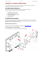
CHAPTER 4: VEHICLE MOUNTING .............................................................................................................. - 29 -
4.1 VEHICLE MOUNT INSTRUCTION ..................................................................................................................... - 29 -
4.2 RAM MOUNT INSTALLATION ......................................................................................................................... - 29 -
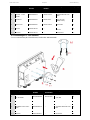
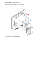
4.3 VESA MOUNT INSTALLATION ....................................................................................................................... - 32 -
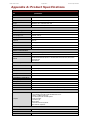
APPENDIX A: PRODUCT SPECIFICATIONS ............................................................................................... - 34 -

FM07 User Guide Preface
- 3 -
Copyright © 2018 Winmate Communication Inc. All rights reserved.
No part of this manual may be reproduce, copied, translated, or transmitted in any form or any means,
electronic or mechanical, for any purpose, without the written permission of Winmate Inc.
Trademarks
All product names, trademarks or logos mentioned herein are the properties of their respective owners.
Microsoft, Windows, and the Windows logo are either registered trademarks or trademarks of Microsoft
Corporation in the United States and/or other countries. Microsoft products are licensed to OEMs by Microsoft
Licensing, Inc., a wholly owned subsidiary of Microsoft Corporation.
All other brand and product names are trademarks or registered trademarks of their respective owners.
NOTE:
Display images shown may vary slightly from actual display. Information in this manual is
subject to change without prior notification.
Disclaimer
Winmate Inc. reserves the right to make any product changes without notice, including circuits and/or
software described or contained in this manual in order to improve design and/or performance. Winmate Inc.
assumes no responsibility or liability for the use of the described product (s), conveys no license or title under
any patent, copyright, or masks work rights to these products, and makes no representations or warranties
that these products are free from patent, copyright, or mask work right infringement, unless otherwise
specified. Applications that are described in this guide are for illustration purposes only. Winmate Inc. makes
no representation or warranty that such application will be suitable for the specified use without further testing
or modification.
Warranty
Winmate Inc. warrants that each of its products is free from material and workmanship defect for a period of
one year starting from the invoice date. If the customer discovers a defect, Winmate Inc. will, at its option,
repair or replace the defective product at no charge to the customer, provided it is returned during the warranty
period, with transportation charges prepaid. The returned product must be properly packaged in its original
packaging to obtain warranty service.
Advisory Conventions
Four types of advisories are used throughout the user manual to provide helpful information or to alert you to
the potential for hardware damage or personal injury. These are Notes, Important, Cautions, and Warnings.
The following is an example of each type of advisory.
NOTE:
A note is used to emphasize helpful information
IMPORTANT:
An important note indicates information that is important for you to know.
CAUTION/ ATTENTION
A Caution alert indicates potential damage to hardware and explains how to avoid the
potential problem.
Une alerte d’attention indique un dommage possible à l’équipement et explique comment
éviter le problème potentiel.
WARNING!/ AVERTISSEMENT!
An Electrical Shock Warning indicates the potential harm from electrical hazards and how to
avoid the potential problem.
Un Avertissement de Choc Électrique indique le potentiel de chocs sur des emplacements
électriques et comment éviter ces problèmes.

FM07 User Guide Preface
- 4 -
FCC Statement
This device complies with part 15 FCC rules.
Operation is subject to the following two conditions:
This device may not cause harmful interference.
This device must accept any interference received including
interference that may cause undesired operation
This equipment has been tested and found to comply with the limits for a class "B" digital device, pursuant to
part 15 of the FCC rules. These limits are designed to provide reasonable protection against harmful
interference when the equipment is operated in a commercial environment. This equipment generates, uses,
and can radiate radio frequency energy and, if not installed and used in accordance with the instruction manual,
may cause harmful interference to radio communications. Operation of this equipment in a residential area is
likely to cause harmful interference in which case the user will be required to correct the interference at him
own expense.
CE Notice (European Union)
Electromagnetic Compatibility Directive (2014/30/EU)
EN55024: 2010/ A1: 2015
o IEC61000-4-2: 2009
o IEC61000-4-3: 2006+A1: 2007+A2: 2010
o IEC61000-4-4: 2012
o IEC61000-4-5: 2014
o IEC61000-4-6: 2014
o IEC61000-4-8: 2010
o IEC61000-4-11: 2004
EN55032: 2012/AC:2013
EN61000-3-2:2014
EN61000-3-3:2013
Low Voltage Directive (2014/35/EU)
EN 60950-1:2006/A11:2009/A1:2010/A12:2011/ A2:2013
This equipment is in conformity with the requirement of the following EU legislations and harmonized standards.
Product also complies with the Council directions.

FM07 User Guide Read Me First
- 5 -
Read Me First
Follow and adhere to all warnings and instructions in this manual. For your safety, please read all safety and
operating instructions before using the product. Keep this manual for future reference.
ATTENTION: Pour réduire le risque d’incendie ou de choc électrique ne pas exposer
l’appareil à la pluie ou à l’humidité. VERIFIER que le cordon électrique est la prise murale pour
un delai d’inactivite prolongé. Pour arrêter complètement l’alimentation de l’appareil,
débranchez le cordon d’alimentation de la prise AC. N’enlever ni le capot arrière ni les pièces
internes de l’appareil. Contactez un personnel qualifié si nécessaire.
AVERTISSEMENT ÉLECTRIQUE
Utilisé pour les instructions destinés à alerter l’utilisateur d’un CHOC
ÉLECTRIQUE mortel ou de blessure grave en cas d’utilisation incorrecte de
l’unité.
SA1965
AVERTISSEMENT
Utilisé pour les instructions destinés à alerter l’utilisateur d’un risque mortel ou
de blessure grave en cas d’utilisation incorrecte de l’unité.
SA1966
ATTENTION: Pour réduire le risque d’incendie ou de choc electrique ne pas exposer
l’appareil à la pluie ou à l’humidité FAIRE le cordon électrique est DÉBRANCHÉ DE LA PRISE
MURALE DANS UN DELAI DE PROLONGER INACTIVITÉ. De se désengager totalement LE
POUVOIR DE L’UNITE, S’IL VOUS PLAÎT DEBRANCHER LE CORDON D’ALIMENTATION
DE LA PRISE AC. NE PAS Romove le capot arrière, pas de PIÈCES À L’INTÉRIEUR.
Contactez un personnel qualifié S’il faut le réparer.
ELECTRIQUE AVERTISSEMENT
Sert aux instructions destin es alerter l’utilisateur d’un CHOC ÉLECTRIQUE
mortel ou de blessure grave en cas d’utilisation incorrecte de l’unit.
SA1965
AVERTISSEMENT
Sert aux instructions destin es alerter l’utilisateur d’un risque mortel ou de
blessure grave en cas d’utilisation incorrecte de l’unit .
SA1966

FM07 User Guide Read Me First
- 6 -
Informations de sécurité (FR)
Suivez et respectez tous les avertissements et instructions figurant sur l’écran. Pour votre sécurité, s’il vous
plaît lire toutes les consignes de sécurité et de fonctionnement avant d’utiliser le device. Gardez ce manuel
pour référence future.
1. Lire avec attention toutes les recommandations et precautions d’emploi avant d’utiliser ce produit.
2. Veuillez conserver ces recommandations et précautions pour référence future.
3. Lire et comprendre tous les avertissements énumérés dans les précautions d’emploi.
4. Suivre toutes les précautions d’emploi pour utiliser ce produit.
5. Utiliser exclusivement un chiffon sec pour nettoyer ce produit.
6. Ne pas placer le produit près de toute source de chaeur telle que radiateurs, arrivées d’air chaud,
fourneaux ou autres appareils générant de la chaleur (incluant les amplificateurs producteurs de chaleur)
.
7. Ne pas négliger la sécurité que procure un branchement polarisé ou avec raccordement à la terre, Un
branchement polarisé comprend deux fiches dont l’une est plus large que l’autre. Un branchement à la
terre comprend deux fiches plus une troisième reliée à la terre. Si la fiche secteur fournie ne s’insert pas
dans votre prise de courant. consulter un ‘électricien afin de remplacer votre prise obsolète.
8. Protéger le cordon d’alimentation de tout écrasement ou pincement, particulièrement au niveau des
fiches, des réceptacles utilisés et à l’endroit de sortie de l’appareil. Ne pas casser la fiche de terre du
cordon d’alimentation.
9. Utiliser uniquement les accessoires spécifiés par le constructeur.
10. Utilisez seulement des accessoires spécifiés par le manufacturier ou vendus avec le
produit.
11. Débrancher cet appareil lors d’orages ou s’il n’est pas utilize pendant une longue période.
12. Faire exécuter le service par du personnel qualifié. Une intervention technique est requise lorsque
l’appareil a été endommagé ou n’opère pas normalement.
Safety Information (EN)
Follow and adhere to all warnings and instructions on the screen. For your safety, please read all safety and
operating instructions before using the device. Keep this manual for future reference.
1.
Carefully read all recommendations and precautions for use before using this product.
2.
Retain all recommendations and precautions for future reference as necessary.
3.
Read and be sure to understand all warnings listed in the precautions.
4.
Follow all operating precautions when using this product.
5.
Use only a dry cloth to clean this product.
6.
Do not place the product near any heat sources such as radiators, warm air intakes, stoves or other heat-
generating devices (including amplifiers or other heat producing equipment).
7.
Do not disregard the safety that a polarized or grounded connection can provide. A polarized connection
consists of two plugs, one of which is larger than the other. A grounded connection has two blades and a
third one that is grounded. If the main plug provided cannot be inserted into your outlet, consult an
electrician to replace your obsolete outlet.
8.
Protect the power cord from being crushed or pinched, particularly in the area of the plugs, any
receptacles used, and the point of exit from the apparatus. Do not break off the ground pin of the power
cord.
9.
Use only accessories specified by the manufacturer.
10.
Use only with accessories specified by the manufacturer or sold with the product.
11.
Unplug this apparatus during lightning storms or when it is not being used for long
periods.
12.
Refer all servicing to qualified service personnel. A technical intervention is required when the apparatus
has been damaged in any way or does not operate normally
About This Guide
This User Guide provides instruction for the system administrator to follow when configuring and using the
FM07 Vehicle Mount Computer. This User Guide has been developed for a FM07 with Windows® 10 IoT
Enterprise operating system.

FM07 User Guide Chapter 1 Introduction
- 7 -
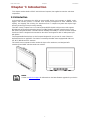
Chapter 1: Introduction
This chapter contains details of FM07 Vehicle Mount Computer, lists supplied accessories and shows
components.
1.1 Introduction
In the warehouse environment, the ability to mount mobile devices and computers to forklifts, trucks,
taggers, and inventory pickers, is essential. From inventory management to order fulfillment, asset
tracking, and shipping and receiving, the warehouse floor is complex ecosystem that requires high-
efficiency technology to keep it running smoothly.
The FM07 Vehicle Computer runs on an Intel® Celeron N3350 (Apollo Lake) processor and supports
Windows® 10 IoT Enterprise operating system. The FM07 features projected capacitive touch screen
with 1024 x 600 pixel resolution. The FM07 delivers flexibility and mobility in a vehicle mounted computer
form factor. FM07 is designed to be mounted on the vehicle and supports 9~36V DC wide power input
with ignition.
The programmable function keys on the front panel designed for easy access for some of the most
important functions or application. For wireless connectivity the tablet comes equipped with SIM card
slot, Wi-Fi, WWAN and GPS antennas.
This vehicle-mount computer is built to endure the rigors of the warehouse, and designed to fit
seamlessly into forklifts and other warehouse vehicles.
NOTE:
Contact our technical support for information on the latest firmware upgrade for your device.

FM07 User Guide Chapter 1 Introduction
- 8 -
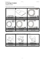
1.2 Package Contents
Standard Accessories
Before using this device, make sure that all the items listed below are present in your package:
FM07 Computer
User Guide
M12 Power Cable
Varies by product specifications
9152111I109C
94J004L040K1
M12 RS232 Cable
M12 LAN Cable
M12 DIDO/ CANBus Cable
94E0123090K0
94I0120080K0
94E012L110K0
Optional Accessories
The following accessories may be included in your package based on your order:
Mounting Kit 1 –
No Drill Solution
Mounting Kit 2 –
Drill Solution
Mounting Kit 3 –
Keyboard Mounting
98K000A0005Y
98K000A0006P
98K000A000AO

FM07 User Guide Chapter 1 Introduction
- 9 -
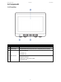
1.4 Components
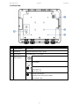
1.4.1 Front View
No
Item
Description
1
7-inch Touch Screen
Acts as one of the inputs for the device
2
Function Keys
5 programmable function keys that can be configured by Win-Set ® Utility
3
LED Indicators
Power LED indicator
On: Power is on
Off: Power is off
Storage LED indicator
Blinking: Data is being read or written
Off: System is idle

FM07 User Guide Chapter 1 Introduction
- 10 -
1.4.2 Rear View
No
Item
Description
1
1 Watt Speaker
Emits sound
2
RAM Mount
RAM base dimensions: 38.1 x 30 mm
3
VESA Mount
VESA dimensions : 75 x 75 mm
4
Physical Buttons and
LED Indicators
Power button
Reset button
Power LED indicator
On: Power is on
Off: Power is off
Storage LED indicator
Blinking: Data is being read or written
Off: System is idle

FM07 User Guide Chapter 1 Introduction
- 11 -
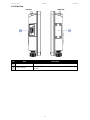
1.4.3 Side View
Left Side
Right Side
No
Item
Description
1
USB A Type
USB A Type connector with protection cap.
2
SIM Card Slot
SIM Card Slot is located under protection cover secured with 4
screws

FM07 User Guide Chapter 1 Introduction
- 12 -
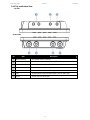
1.4.4 Top and Bottom View
Top Side
Bottom Side
No
Item
Description
1
WWAN Antenna
For WWAN antenna (Optional)
2
GPS Antenna
For GPS antenna
3
Wi-Fi Antenna (Main)
For Wi-Fi antenna (Optional)
4
Power Input
9V-36V DC power input with ignition control
5
DIDO, CANBus
DIDO & CANBus connector (M12 type)
6
LAN
Gigabit Ethernet LAN 10/100/100 Mbps connector (M12 type)
7
RS232
RS232 connector (M12 type)

FM07 User Guide Chapter 2 Hardware
- 13 -
Chapter 2: Hardware
This chapter describes system hardware of FM07 Vehicle Mount Computer.
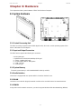
2.1 System Hardware
2.1.1 Central Processing Unit
The FM07 is running on Intel® Celeron N3350 (Apollo Lake), 2M Cache, and the operating system of this
device is Windows 10 IoT Enterprise.
2.1.2 Input and Output Connectors
The FM07 device supports the following I/O connectors:
• RS232 (M12 type)
• Gigabit Ethernet LAN 10/100/100 Mbps (M12 type)
• 1 x DIDO, CANBus (M12 type)
• 1 x Power input 9-36V DC with ignition
• 1 x SIM Card Slot
• 1 x USB A-Type
2.1.3 System Memory
The main system memory is 2GB SODIMM DDR3L-1600 (up to 8GB).
2.1.4 Audio Interface
Your device is equipped with one speaker which is located on the back cover.
2.1.5 WLAN
Your device has an 802.11 a/b/g/n/ac network card that can be used with internal or external antennas.
2.1.6 WWAN
Using a SIM card for network connection, your device supports Wireless Wide Area Networking (WWAN).

FM07 User Guide Chapter 2 Hardware
- 14 -
2.2 Power
2.2.1 Vehicle DC Power Supply
The power input voltage range for the FM07 is between 9 to 36V DC with ignition control.
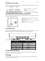
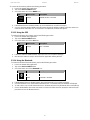
2.3 Power Control
2.3.1 Power Button
Power button is located on the rear side of the
device. When the FM07 is connected to the
external power and the power button is ON, the
device can be powered on.
2.3.2 Ignition Control
The FM07 supports power ignition function.
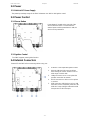
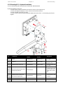
2.4 External Connectors
Power OFF the FM07 before connecting cables to any port.
1. 9-36V DC Power Input with Ignition Control.
2. DIDO & CAN Bus M12 connector allows
direct linking into vehicle, enable access to
wide range of vehicle data.
3. LAN port connects to on access point that
provides connection to network.
4. RS232 connects to a device such as printer
or scanner.
5. USB connects to USB devices such as USB
flash drive, mouse, keyboard, printer etc. this
USB also accept a dongle cable with a USB
host port and a USB Client port.

FM07 User Guide Chapter 2 Hardware
- 15 -
2.4.1 Connector Description
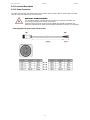
2.4.1.1 Power Connector
The FM07 has M12 type 4 pin male power input connector which accepts 9-36V DC power input. Use power
cable to connect the FM07 to the source of power.
WARNING!/ AVERTISSEMENT!
This procedure requires a trained service personnel only, improper installation can
cause serious damage to the vehicle or the device.
Cette procédure nécessite un personnel de maintenance qualifié uniquement, une
mauvaise installation peut causer des dommages importants au véhicule ou le dispositif.
Pin Assignment and signal names of Power Cable

FM07 User Guide Chapter 2 Hardware
- 16 -
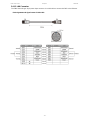
2.4.1.2 LAN Connector
The FM07 has M12 type 12 pin power input connector. Use LAN cable to connect the FM07 to the Ethernet.
Pin Assignment and signal names of LAN Cable

FM07 User Guide Chapter 2 Hardware
- 17 -
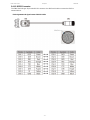
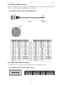
2.4.1.3 RS232 Connector
The FM07 has M12 type 12 pin male RS-232 connector. Use IP65 serial cable to connect the FM07 to
external devices.
Pin Assignment and signal names of RS232 Cable

FM07 User Guide Chapter 2 Hardware
- 18 -
2.4.1.5 DIDO &CANBus Connector
The DIDO & CANBus connector is a M12 type 12 pin waterproof connector located on the bottom side of the
device. The connector supports a CANBus cable or a DIDO cable.
Pin Assignment and signal names of DIDO &CANBus Cable
2.4.1.4 USB 2.0 (D-9 Female) Connector
The FM07 has USB 2.0 connector covered by protection cover and located on the side.
Pin Assignment and signal names of USB2.0 connector
0.5A @ 5 V
Pin №
Signal Name
Pin №
Signal Name
1
+5V
2
Data-
3
Data+
4
GND

FM07 User Guide Chapter 2 Hardware
- 19 -
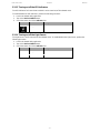
2.5 Antenna Connections
The FM07 is equipped with an 802.11 radio and can be ordered with external remote mount antennas. GPS and
WWAN require external remote mount antennas.
1. Wi-Fi 802.11 External Antenna Connectors
(Optional)
2. GPS External Antenna Connector
3. WWAN External Antenna Connectors (Optional)
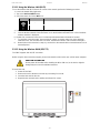
2.6 External Vehicle Remote Antenna Installation
The FM07 is equipped with connectors for additional external antenna (Wi-Fi, GPS or WWAN), to install the
antenna please perform the following:
1. Remove the rubber cap on the SMA connector before
installing the antenna.
2. Align the antenna with the SMA connector and fasten it as
following picture.
3. Adjust the position of external antennas.
2.7 Function Keys
The integrated keypad contains ten programmable keys, F1~ F5 are user programmable keys. Key
Mapping is configured via the HotTab utility. See programmable key to remap these keys.
The default values of front panel function keys are:
Function Key
Default Key Value
F1
Press to open HotTab
F2
Calculator
F3
Notepad
F4
Volume Up
F5
Volume Down
2.7 USB Keyboard/ Mouse
A standard USB keyboard or mouse can be attached to the FM07 using the appropriate adapter cable.
Attach the cable to the FM07 USB-A type connector.
2.8 Display
The FM07’s display measures 7 inches diagonally, display resolution is 1024 x 600 pixel resolution and
bonded with projected capacitive touch.

FM07 User Guide Chapter 3 Software
- 20 -
Chapter 3: Software
This chapter and describes how to operate FM07 Vehicle Mount Computer.
3.1 Introduction
This section includes the software and hardware installation, the FM07 configuration, the wireless
communication, and some other optional features. Since the FM07 configuration varies by your order, utility
programs for its configurations and operations, the examples describe in this section are to be used as a
guideline only; therefore, the function configuration of the device might vary.
3.1.1 Operating System
The operating system of the FM07 is Windows 10 IoT Enterprise.
3.1.2 Windows 10 IoT Enterprise
We assume the user is very familiar with various features and options of Microsoft Windows OS. Therefore,
this section will describe the specific software and utility programs that related to the device usage and the
Windows 10 environment.
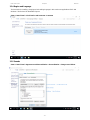
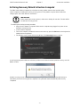
3.1.3 Setting up Windows for the First Time
This section details how to setup different version of the Windows that may be installed on the vehicle
computer for the first time.
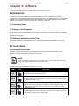
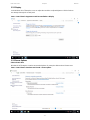
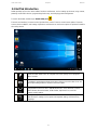
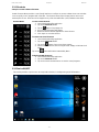
3.2 Control Panel
3.2.1 Using the Touch Screen
The touch screen is a touch-sensitive device that allows you to control and make selections on the
device by controlling the location of the pointer on the screen.
NOTE:
Do not use sharp or pointed objects on the touch screen. These objects may scratch the
screen. Use only the stylus pen or the tip of your finger.
Here are some common terms when using the touch screen.
Gesture
Action
Description
Single
Tap
Tap gently on the touch screen to select or open an item. Tapping is the same
as clicking the left mouse button of a pc
Double-
tap
Rapidly tap twice on the touch screen. This action is similar to double-clicking
the left mouse button of a pc.
Press
and hold
Press and hold the finger/ stylus lightly on the display. A big circle appears to
indicate that a pop-up menu will soon appear. Lift up the stylus and a pop-up
menu appears. Select the desired function. This action is similar to a right
mouse click on a pc.
Drag
Hold the finger/ stylus on the screen and drag across the screen to select text
and images or move icons to a new location.
La page est en cours de chargement...
La page est en cours de chargement...
La page est en cours de chargement...
La page est en cours de chargement...
La page est en cours de chargement...
La page est en cours de chargement...
La page est en cours de chargement...
La page est en cours de chargement...
La page est en cours de chargement...
La page est en cours de chargement...
La page est en cours de chargement...
La page est en cours de chargement...
La page est en cours de chargement...
La page est en cours de chargement...
La page est en cours de chargement...
La page est en cours de chargement...
-
 1
1
-
 2
2
-
 3
3
-
 4
4
-
 5
5
-
 6
6
-
 7
7
-
 8
8
-
 9
9
-
 10
10
-
 11
11
-
 12
12
-
 13
13
-
 14
14
-
 15
15
-
 16
16
-
 17
17
-
 18
18
-
 19
19
-
 20
20
-
 21
21
-
 22
22
-
 23
23
-
 24
24
-
 25
25
-
 26
26
-
 27
27
-
 28
28
-
 29
29
-
 30
30
-
 31
31
-
 32
32
-
 33
33
-
 34
34
-
 35
35
-
 36
36


dans d''autres langues
- English: Winmate FM07 User manual
Documents connexes
-
 Winmate FM07 Manuel utilisateur
-
 Winmate FM10A Manuel utilisateur
-
 Winmate FM10Q Guide de démarrage rapide
-
 Winmate FM07A Manuel utilisateur
-
 Winmate G-Win Series Guide de démarrage rapide
-
 Winmate M900P Manuel utilisateur
-
 Winmate M900P Guide de démarrage rapide
-
 Winmate M101B Series Manuel utilisateur
-
 Winmate M101PR Manuel utilisateur
-
 Winmate M116PT Manuel utilisateur


