
PL-REM
Manual
English....................Page 2
Nederlands.......Pagina 12
Français...............Page 22
Deutsch...............Seite 32
LINK Driver
12-09-22

2
Table of contents
Technical specifications
Box contents
Installation instructions
Pairing Handheld Transmitter & controller
Handheld transmitter functions
Replacing transmitter battery
Change relay A/B mode
Troubleshooting
Page 3
Page 4
Page 5-6
Page 7
Page 8
Page 8
Page 9
Page 10

3
ENG
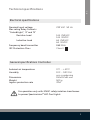
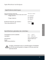
Technical specifications
Electrical specifications
General specifications Controller
Ambient air temperature
Humidity
Dimensions
Weight
Ingress protection rate
0°C ... +40°C
10% ... 90% RH
non condensing
150x157x51 mm
500 g
IP54
Nominal Input voltage
Max rating Relay Contacts
“Color&Light”, “A” and “B”
Resistive Load
Inductive Load
Frequency band transmitter
IEC Protection Class
230 VAC 50 Hz
14A 250VAC
14A 30VDC
6A 250VAC
6A 30VDC
868 MHz
Class II
For operation only with 12VAC safety isolation transformer
to power Spectravision® LED Pool Lights

4
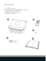
Box contents
12
45
1. PL-REM controller
2. Handheld transmitter (DuraLink™ version)
3. Spare battery (type A23 12V)
4. Screws (4x) & wall plugs (4x)
5. Owners’s manual
3

5
ENG
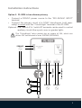
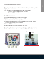
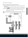
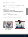
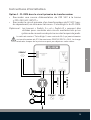
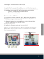
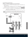
Installation instructions
230VAC
Garden lights
Pool cover
230VAC 230VAC
12VAC
Option 1: PL-REM in transformer primary
• Connect a 230VAC power source to the “220-240VAC INPUT”
terminal
• Connect the primary circuit of a 12VAC transformer (sold sepa-
rately) in series with the “Color&Light” terminal of the PL-REM.
The “Color&Light” relay contact has an output of 14A, which can
drive a 12V transformer of max. 3000W (220Vx14A).
Optional: The “Switch A” & “switch B” terminals can be used to control
auxiliary circuits like a pool cover or garden lights.

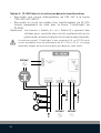
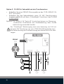
6
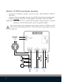
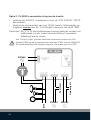
Option 2: PL-REM in transformer secondary
• Connect a 230VAC power source to the “220-240VAC INPUT”
terminal
• Connect the secondary circuit of a 12VAC transformer (sold sepa-
rately) in series with the “Color&Light” terminal of the PL-REM.
The “Color&Light” relay contact has an output of 14A, or 170W on a 12V
transformer secondary (14Ax12V). The total load of pool lights can not
exceed this.
Optional: The “Switch A” & “switch B” terminals can be used to control
auxiliary circuits like a pool cover or garden lights.
230VAC
Garden lights
Pool cover
230VAC 230VAC
12VAC

7
ENG
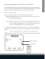
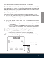
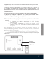
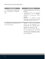
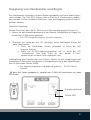
Pairing handheld transmitter & controller
The handheld transmitter is already paired in the factory and ready to
use. The PL-REM can pair with up to 6 handheld transmitters. In case a
problem arises, the pairing process can be done manually:
Manual Pairing process:
Make sure the PL-REM is connected to a power source.
1. Press the pairing button on the small circuit board, inside the con-
troller for at least 5 seconds.
--> The LED will start to blink fast
2. Within 25 seconds, press any button on the handheld transmitter.
--> If the transmitter is paired correctly, the LED will flash slowly for 5 times
--> If the PL-REM pairing memory is full, the LED will flash 15 times.
This means 6 handheld devices have already been paired.
To unpair all handheld transmitters with the controller: Push the pair-
ing button for at least 5 seconds, then do nothing for at least 25 sec-
onds.
--> The pair memory will be erased - the green LED will flash 5x on/o.
Green LED
Pairing button
If no transmitters are paired, the PL-REM-200 will accept messages from any transmitter!

8
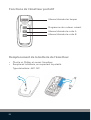
Handheld transmitter functions
Toggle the lamps ON/OFF
Go to next color scenario
Toggle Output A ON/OFF
Toggle Output B ON/OFF
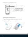
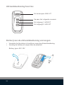
Replacing transmitter battery
+
-
• Remove the philips head screw and open the transmitter
• Replace the battery, respecting the polarity
Battery type: A23 12V

9
ENG
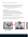
The relays A & B can be used to control auxiliary circuits like garden
lighting or a pool cover.
The operation mode of these relays can be modified:
Option 1: Normal open/closed contact
Option 2: Pulsed contact
Modification process:
1. Locate the 5 pinholes on the circuit board
2. Make a connection between pin 1 and 2
(use a piece of wire, or a paperclip)
3. Power ON the device by connecting a 230VAC power source
to the 220-240VAC INPUT terminal
4. Power OFF the device
5. Remove the connection between pin 1 and 2
Every time the above process is repeated, the A & B relays switch
between Normal open/closed mode and Pulsed operation mode
Pin 1 Pin 2
Change Relay A/B mode

10
PROBLEM SOLUTION
The controller doesn’t react
to transmitter commands
• Check the battery of the hand-
held transmitter
• The transmitter is not paired-
correctly with the controller.
Repeat the pairing process
• Reduce the distance between
handheld transmitter and PL-
REM and/or remove obstacles
The pool lights don’t work • Check if all connections are
made according to the electri-
cal scheme on page 5 or 6.
• Check if the “Color&Light” out-
put terminals of the controller
switch on and of when pushing
the on/o button on the trans-
mitter.
Troubleshooting

11
ENG

12
Inhoudstafel
Technische specificaties
Inhoud van de doos
Installatie instructies
Afstandsbediening en controller koppelen
Afstandsbediening functies
Batterij van de afstandsbediening vervangen
Relais A/B modus veranderen
Probleemoplossing
Pagina 13
Pagina 14
Pagina 15-16
Pagina 17
Pagina 18
Pagina 18
Pagina 19
Pagina 20

13
NL
Technische specificaties
Electrische specificaties
Algemene specificateis controller
Omgevingstemperatuur
Vochtigheidsgraad
Afmetingen
Gewicht
IP klasse
0°C ... +40°C
10% ... 90% RH
non condensing
150x157x51 mm
500 g
IP54
Ingangsspanning (nominaal)
Max vermogen Relais contact A en B
“Color&Light”, “A” and “B”
Resistieve Belasting
Inductieve Belasting
Frequentie band afstandsbediening
IEC Beschermingsklasse
230 VAC 50 Hz
14A 250VAC
14A 30VDC
6A 250VAC
6A 30VDC
868 MHz
Class II
Uitsluitend te gebruiken met een veiligheidstransformer
om DURAVISION® LED verliching aan te sturen

14
Inhoud van de doos
12
45
1. PL-REM controller
2. Afstandsbediening (DuraLink™ versie)
3. Reserve batterij (type A23 12V)
4. Schroeven (4x) & muurpluggen (4x)
5. Handleiding
3

15
NL
Installatie instructies
230VAC
Garden lights
Pool cover
230VAC 230VAC
12VAC
Optie 1: PL-REM in primaire kring van de transfo
• Verbind een 230VAC voedingsbron met de “220-240VAC INPUT”
aansluitklem
• Verbind de primaire kant van een 12VAC transfo (afzonderlijk ver-
krijgbaar) in serie metde “Color & Light” klemmen van de PL-REM
Het “Color & Light” contact heeft een maximum output van 14A, zodat
de aangesloten transfo maximaal 3000W mag zijn (220V x 14A)
Optioneel: De “A” & “B” aansluitklemmen kunnen gebruikt worden om
additionele circuits (zoals tuinverlichting of zwembad-
afdekking) aan te sturen

16
Optie 2: PL-REM in secundaire kring van de transfo
• Verbind een 230VAC voedingsbron met de “220-240VAC” INPUT
aansluitklem
• Verbind de primaire kant van een 12VAC transfo (afzonderlijk ver-
krijgbaar) in serie met de “Color&Light” klemmen van de PL-REM.
230VAC
Garden lights
Pool cover
230VAC 230VAC
12VAC
Het “Color & Light” contact heeft een maximum output van 14A,
oftewel 170W op de secundaire kant van een 12VAC transfo (14Ax12V).
De totale belasting van lampen mag dus niet meer zijn van 170W
Optioneel: De “A” & “B” aansluitklemmen kunnen gebruikt worden om
additionele circuits (zoals tuinverlichting of zwembad-
afdekking) aan te sturen

17
NL
Afstandsbediening en controller koppelen
Groene LED
koppel-knop
De afstandsbediening is reeds gekoppeld van in de fabriek en is klaar
voor gebruik. The PL-REM-200 kan gekoppeld worden met maximaal
6 afstandsbedieningen. In probleemgevallen kan men de afstandsbe-
diening ook manueel koppelen.
Manueel koppel proces:
Zorg ervoor dat de PL-REM verbonden is met een voeding en transfo.
1. Druk op de rode koppel-knop op het kleine printplaatje binnen
in de controller, gedurende 5 seconden.
--> de rode LED zal nu snel knipperen
2. Druk op eender welke knop van afstandsbediening binnen
de 25 seconden
--> Als de afstandsbediening correct gekopeld is, zal de groene LED 5x
traag knipperen
--> Als er al 6 verschillende afstandsbedieningen met de controller gekoppeld
zijn, zal de rode LED 15x knipperen. Dit wil zeggen dat het geheugen vol is
Om ALLE afstandsbedieningen te ontkoppelen van de controller:
Druk op de rode koppel-knop gedurende 5 seconden.
Druk daarna op GEEN ENKELE knop binnen de 25 seconden.
--> Het geheigen is nu gewist. De groene LED zal 5x knipperen
Als er geen afstandsbedieningen gekoppeld zijn, zal de PL-REM-200 boodschappen
ontvangen van alle afstandsbedieningen!

18
Afstandsbediening functies
Zet de lampen AAN/UIT
Ga naar het volgende scenario
Zet uitgang A AAN/UIT
Zet uitgang B AAN/UIT
Batterij van de afstandsbediening vervangen
+
-
Battery type: A23 12V
• Verwijder het kruiskop schroee en open de afstandsbediening
• Vervang de batterij en respecteer de polariteit

19
NL
Pin 1 Pin 2
Relais A/B modus veranderen
De “A” & “B” aansluitklemmen kunnen gebruikt worden om addi-
tionele circuits (zoals tuinverlichting of zwembadafdekking) aan te
sturen
Optie 1: Normaal open/gesloten contact
Optie 2: Pulserend contact
Modificatie proces:
1. Zoek de 5 ‘pinholes’ op de printplaat
2. Verbind pin 1 met 2 (gebruik een stukje draad of een paperclip)
3. Schakel de PL-REM AAN door een 230VAC voedingsbron aan te
sluiten op de “220-240VAC INPUT” klemmen
4. Zet de PL-REM UIT
5. Verwijder de verbinding tussen pin 1 en 2
Telkens wanneer het bovenstaande proces wordt herhaald,
schakelen de A & B aansluitklemmen om tussen de modus
Normaal open/gesloten (Optie 1) en Pulserend (Optie 2)

20
PROBLEEM OPLOSSING
De controller reageert niet
meer op commando’s van de
afstandsbediening
• Controleer de batterij van de af-
standsbediening
• De afstandsbediening is niet
cor- rect gekoppeld met de
control- ler, herhaal het koppel
proces
• Verminder de afstand tussen de
afstandsbediening en de con-
troller en/of verwijder obstakels
De zwembadverlichting werkt
niet
Probleemoplossing
• Controleer of alle verbindingen
gemaakt zijn volgens het sche-
ma op pagina 15 of 16
• Controleer of de “Color & Light”
output klemmen schakelen
wanneer je op de ON/OFF knop
drukt op de afstandsbediening
La page est en cours de chargement...
La page est en cours de chargement...
La page est en cours de chargement...
La page est en cours de chargement...
La page est en cours de chargement...
La page est en cours de chargement...
La page est en cours de chargement...
La page est en cours de chargement...
La page est en cours de chargement...
La page est en cours de chargement...
La page est en cours de chargement...
La page est en cours de chargement...
La page est en cours de chargement...
La page est en cours de chargement...
La page est en cours de chargement...
La page est en cours de chargement...
La page est en cours de chargement...
La page est en cours de chargement...
La page est en cours de chargement...
La page est en cours de chargement...
La page est en cours de chargement...
La page est en cours de chargement...
La page est en cours de chargement...
La page est en cours de chargement...
-
 1
1
-
 2
2
-
 3
3
-
 4
4
-
 5
5
-
 6
6
-
 7
7
-
 8
8
-
 9
9
-
 10
10
-
 11
11
-
 12
12
-
 13
13
-
 14
14
-
 15
15
-
 16
16
-
 17
17
-
 18
18
-
 19
19
-
 20
20
-
 21
21
-
 22
22
-
 23
23
-
 24
24
-
 25
25
-
 26
26
-
 27
27
-
 28
28
-
 29
29
-
 30
30
-
 31
31
-
 32
32
-
 33
33
-
 34
34
-
 35
35
-
 36
36
-
 37
37
-
 38
38
-
 39
39
-
 40
40
-
 41
41
-
 42
42
-
 43
43
-
 44
44


dans d''autres langues
- English: Duratech PL-REM User manual
- Deutsch: Duratech PL-REM Benutzerhandbuch
- Nederlands: Duratech PL-REM Handleiding
Documents connexes
Autres documents
-
Sera LED ballast Information For Use
-
Chamberlain LiftMaster CB124 Le manuel du propriétaire
-
-
Pahlen MA50-25 Le manuel du propriétaire
-
Chamberlain TPD10 Le manuel du propriétaire
-
 Speck pumpen JET wireless control Mode d'emploi
-
-
-
 Key Automation 580IS14A Manuel utilisateur

