Jenn-Air JGD8348CDP17 Guide d'installation
- Catégorie
- Cuisinières
- Taper
- Guide d'installation

Triple Bay Conventional Gas
Prostyle TM Grill Cooktop
Model JGD8348CDP
=JENN-AIR,I
403WEST FOURTHSTREET,NORTH• NEWTON,IA 5020
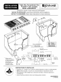
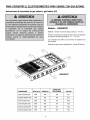
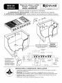
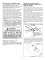
Dimensions shown in both inches and centimenters
NOTICE TO INSTALLER: Leave these instructions with the appliance.
NOTICE TO CONSUMER" Retain these instructions for future reference.
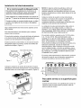
13_6"
34.11 cm
Blower may be
rotated for horizontal
or vertical direction by
loosening nuts
around blower inlet.
Accessible inside
ventilation chamber.
)_
I
I
I
SELECT APPROPRIATE
DUCT CUTOUT
(SEE DUCTING
INSTALLATION INSTRUCTIONS.)
SEE PAGE 2
FOR CUTOUT
DIMENSIONS
f APPLIANCE15" PRESSURE REGULATOR
[38.1 cm]
46 13/16"
3 13/16+ [118.90 cm]
[9.68 cm] _
[40.16 cm] ' '_ IL 3 5/16"
M_N { BOTTOU3 APPLIANCE [8 41 cm]
CL,R*NC,........ ,--?-II 'I--PRESSURE,.+----.JLBO+,O,OE
REQUIRED ........ _ I IREGULATOR EACH END II BURNER BOX
i .BLOWER--"II_W,RE COVER I
II I cox I
I LDRAIN JAR I LEND OF
I I I_BURNER
AI_I 14" I 28 11/16 ° __l BOX
[35.86 cm] I [72+87 cm] -I
INSTRUCTIONS TO INSTALLER:
• Dimension "A" - provide 2" min. (5.08 cm) cabinet clearance to motor for cooling purpose.
• NOTE: Where possible, 6" (15.54 cm)is recommended for motor/blower service.
• Side Clearance: Grills installed near a side wall must allow a minimum clearance of
8" (20.32 cm).
• Access must be provided to remove and empty grease container.
8101 P658-60
(11-04-00)

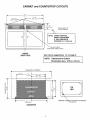
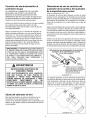
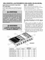
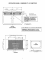
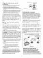
CABINET and COUNTERTOP CUTOUTS
E
45¾"
9[ (116.2 cm) r
I _ 22Y8" Ref
(F__CUTLINES _ (58.11 cm) r i
I
©
\
' t
(17.46-22 cm)
*Recommend 8" for
Custom Cabinetry.
NOTE: LOWER CONTROL
PANEL IS REQUIRED
IF THIS DIMENSION
EXCEEDS 53/_'' (14.60 cm).
SEE PAGE 3 ABOUT
REINFORCING CABINET FRONT
CABINET
(FRONTVIEW)
See cutout suggestions 1-4 on page 6.
NOTE: Tolerances for Cutout
Dimensions are _+1/16 in (.16 cm)
IT
I-
0.
LU
t'_ =
LU
I--
Z
8
As required by installation
< <[ (76.2 cm) 453/k" t
(116.2 cm)l __
I,
< 46 13/16"
(118,90
C0UNTERTOP
. E &4oo
o3._ Lo
/ \
TOP
VIEW
\
REMOVE CORNER SUPPORTS AS NEEDED
TYP. (4) PLS.

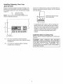
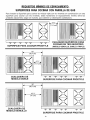
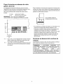
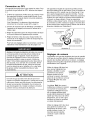
Installing Cabinetry Over Your
Jenn-Air Grill
Minimum horizontal clearance between the edge of the
appliance and combustible construction extending from
the cooking surface to 18" (45.7 cm) above the cooking
surface is:
13/4" (4.45 cm) at rear
8" (20.32 cm) at sides
NOTE: This is not the recommended clearance, but
minimum allowable clearance.
__
18"
(45._ cm)
8"--'1
(20.3 cm)
@
MIN. CLEARANCE
*A
B
= 30" (76.2 cm) minimum vertical clearance
between cooking surface and construction above
the appliance.
= 13" (33.02 cm) maximum depth of cabinets
installed above cooking top.
Avoid use of cabinets above cooktop for storage space to
eliminate associated potential hazards such as reaching
over open flames.
Dotted lines indicate range
hood construction.
* To eliminate the risk of burns or fire by reaching over
heated surface units, cabinet storage space located
above the surface units should be avoided. If cabinet
storage is to be provided, the risk can be reduced by
installing a range hood that projects horizontally a
minimum of 5 inches beyond the bottom of the
cabinets.
Cabinets Above Cooking Top
Maximum depth of cabinets installed above cooking top is
3 inches.
CAUTION:SOME CABINETS AND BUILDING
MATERIALS ARE NOT DESIGNED TO WITHSTAND
THE HEAT PRODUCED BY THE NORMAL SAFE
COLORATION OR DAMAGE, SUCH AS DELAMINA,
TION, MAY OCCUR:

Installation Of Appliance
In The Commonwealth Of Massachusetts
This product must be installed by a licensed plumber or
gas fitter when installed within the Commonwealth of
Massachusetts.
A "T" handle type manual gas valve must be installed in
the gas supply line to this appliance.
A flexible gas connector, when used, must not exceed a
length of three (3) feet / 36 inches.
Follow accompanying ducting instructions carefully.
This appliance is designed to always be vented outdoors.
The Countertop Cutout, Cabinet Front Cutout and Duct
Opening should be prepared according to the illustration
on pages 1 and 2.
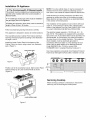
Install the Lower Control Panel in the bottom of the
Cabinet Cutout as shown using screws from Hardware
pack. (Figure 1).
Top View LOWER CONTROL PANEL
NOTE: For some cabinet styles, it may be necessary to
reinforce the front of the cabinet by attaching a brace
from front to rear inside the cabinet under the Burner Box.
Install ductwork per ducting instructions provided. Duct
openings in cabinet are shown in the drawing on page 1.
Make electrical and gas connections as described below
in this section of the instructions.
The installation of this appliance must conform with local
codes or, in the absence of local codes, with the latest
edition of the National Fuel Gas Code, ANSI Z.223.1 USA
or current CAN/CGA-B149 INSTALLATION CODE.
The electrical supply required is 110/120-volt, A.C., 15
amp, 60 Hz. This appliance is equipped with a grounded
type power cord. A grounded outlet must be provided. It is
recommended, for convenience, this outlet be located in
the area shown in the shaded illustration. This appliance,
when installed, must be electrically grounded in
accordance with local codes or, in the absence of local
codes, with the latest edition of the National Electrical
Code ANSI/NFPA No. 70 USA or current CSA
STANDARD C22.1 Canadian Electrical Code part 1.
User may experience occasional circuit tripping if Ground
Fault Circuit Interrupter (GFCI) outlet or breaker is in use.
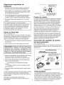
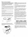
Figure 1
Position unit in the Countertop Cutout. Main Control Panel
should overlap top of Lower Control Panel as shown.
(Figure 2).
10 1/16"
(25.56 cm)
4,
®® @ @® @@
46 13/16" (118.90 cm)
Servicing Cooktop
When servicing cooktop it is necessary to remove the
main top, prior to removing the control panel.
LOWER CONTROL PANEL
Figure 2

Connecting Appliance To Gas Supply
A QUALIFIED SERVICEMAN OR GAS APPLIANCE
INSTALLER MUST MAKE THE GAS SUPPLY
CONNECTION. Leak testing of the appliance shall be
conducted by the installer according to the instructions
given.
Install a manual shutoff valve in an accessible location in
the gas line external to this appliance for the purpose of
turning on or shutting off gas to the appliance.
Make the gas connection to the inlet of the appliance
pressure regulator on this appliance with a 1/2" male pipe
thread. Use an approved pipe joint compound resistant to
the action of LP gas at pipe connections. Test all joints for
gas leaks with a soap and water solution or other
accepted leak detection means. Never test for gas leaks
with an open flame.
CAUTION: WARRANTY IS VOID ON JENN.AIR
EQUIPMENT INSTALLED OTHER THAN AS
RECOMMENDED BY MANUFACTURERI RECOM-
MENDED WALL CAPS AND TRANSITIONS MUST BE
STALLATION.
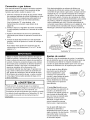
,WARNING
ELECTRICAL GROUNDING INSTRUCTIONS
THIS APPLIANCE IS EQUIPPED WITH A THREE-
PRONG GROUNDING PLUG FOR YOUR
PROTECTION AGAINST SHOCK HAZARD AND
SHOULD BE PLUGGED DIRECTLY INTO A
PROPERLY GROUNDED RECEPTACLE. DO NOT
CUT OR REMOVE THE GROUNDING PRONG FROM
THIS PLUG.
Air Shutter Adjustment
This appliance is shipped from the factory with air shutters
adjusted for use with Natural Gas. If further adjustment is
necessary, or to reset for use with LP, adjust air shutters as
follows:
Grill Burner and Surface Burner
Cartridge Air Shutters
(See Illustrations "A" & "B")
The left hand air shutter controls the rear half of the burner.
The right hand shutter controls the front half. Access to air
shutters on the surface burner cartridge may be found
through openings on the bottom of the cartridge housing.
Slide air shutters backward or forward to increase or
decrease the size of the air opening. Air shutters fit snugly,
so a screwdriver blade or needle nose pliers may be required
to make this adjustment (see illustration).
Observe change in flame appearance as the air shutter is
moved. Adjustment is satisfactory when a clearly defined,
even blue flame results at the high flame setting. The snug
fit of the air shutter assures it will remain positioned correctly.
Grill Burner Air Shutter and Surface Burner
(if so equipped)
"%;"
INSERT SCREWDRIVER
BLADE IN SLOT AND TWIST
WITH SLIGHT PRESSURE TO
ALLOW AIR SHUTTER TO
SLIDE EASILY
Illustration "A"
On any burner, closing the air shutter too far will cause the
flame to become soft and yellow tipped. Opening the air
shutter too wide will cause the flame to blow away from the
burner ports. Proper adjustment will produce a sharp, clearly
defined, even blue flame.
AIR SHUTTER
Illustration "B"

Important Installation Suggestions
1. Chamfer all exposed edges of decorative laminate to
prevent damage from chipping•
2. Radius corners of cutout and file to insure smooth
edges and prevent corner cracking•
3. Rough edges, inside corners which have not been
rounded and forced fits can contribute to cracking of the
countertop laminate•
4. Countertop must be supported within 31 of cutout•
On any burner, closing the air shutter too far will
cause the flame to become soft and yellow tipped•
Opening the air shutter too wide will cause the flame
to blow away from the burner ports. Proper adjustment
will produce a sharp, clearly defined, even blue flame•
Low Flame Adjustment
(See Illustration "C")
This appliance is shipped from the factory with low and
medium flame settings adjusted for use with Natural Gas.
If further adjustment is necessary, or to re-adjust for use
with LP, proceed as follows:
1. Light burner and set control knob for low flame•
2. Remove control knob from valve stem.
CAUTION:NEVER USE A METAL BLADE TO PRY
KNOB OFF: IF KNOB CANNOT BE EASILY
REMOVEDI TUCK THE FOLDS OF A CLOTH
DISHTOWEL UNDER THE KNOB AND PULL THE
TOWEL UPWARD WITH STEADY, EVEN PRESL
SURE.
3. Insert a slender, thin-blade screwdriver into the recess
at center of valve stem and engage blade with slot in
adjusting screw•
4. Turn center stem adjusting screw to set flame size.
•.. clockwise to reduce•
•.. counterclockwise to increase•
5. Replace control knob when adjustment is completed•
Proper adjustment will produce a stable, steady blue flame
of minimum size. The final adjustment should be checked
by turning knob from high to low several times without
extinguishing the flame•
This adjustment, at low setting, will automatically provide
the proper flame size at medium setting•
Pressure Testing
The maximum gas supply pressure for the appliance
pressure regulator supplied on this appliance is 141 W.C.
The test pressure for checking this appliance pressure
regulator must be at least 61 W.C. for Natural Gas, and at
least 111 W.C. for LP. It is shipped from the factory set for
Natural Gas at 51 W.C.
This appliance and its individual shutoff valve must be
disconnected from the gas supply piping system during
any pressure testing of that system at test pressures in
excess of 1/21 PSIG (3.5 k Pa).
This appliance must be isolated from the gas supply
piping system by closing its individual manual shutoff
valve during any pressure testing of the gas supply piping
system at test pressures equal to or less than 1/21 PSIG
(3.5 k Pa).
Appliance Pressure Regulator
Conversion
(See Illustration "D")
This unit is supplied with a Maxitrol Appliance Pressure
Regulator• Follow the instructions in illustration "D".
MAXITROL APPLIANCE PRESSURE REGULATOR
APPLY DOWNWARD
FINGER PRESSURE
AT DISC EDGES TO
ER_I LP REPLACE PIN IN CAP
CONVERT
CAP I T I_ APPLY
_,1_ AND PI_..- ° SIDEWARD
FINGER
NAT t ,,--r "° N.__A_A PRESSURE TO I LP
i_oJ I , REMOVE PIN , --
_ _FROM CAP @
Illustration "D"
High Altitude Notice
The specified gas burner ratings typically apply to
elevations up to 2000 feet. For higher altitudes, the rates may
need to be reduced to achieve satisfactory operation• A
local certified gas servicer will be able to advise if a reduction
is necessary.
Illustration "C"
CLOCk, VISE
TO REDUCE
I1 FLAME SIZE
COU NTERCLOC_,VISE
TO INCREASE FLAME
SIZE

Conversion To LP Gas
This appliance is shipped from the factory equipped for
use with Natural Gas. To convert it from Natural Gas for
use with LP Gas, perform steps 1 through 4.
1. Remove Natural Gas orifice hoods. Install color coded
orifice hoods supplied. Located in a pack attached to
the outer plenum area of this appliance.
(See Illustration "E", below, and LP Gas Conversion
instructions page 8).
2. Invert cap in convertible pressure regulator (if so
equipped) located at entrance to gas manifold.
3. Adjust air shutters on individual burners for proper
flame appearance.
4. Adjust low flame setting at each burner by turning
adjustment screw in center of valve stem.
To make these conversions adjustments follow the
instructions and illustrations ("A" through "E", pages
5-7).
This appliance is shipped from the factory with orifice
hoods drilled for use with Natural Gas. To convert from
Natural Gas to LP, apply a 1/21 open-end wrench to hex
section of orifice hood. Turn counterclockwise to remove.
Save the Natural Gas orifice hoods just removed from this
appliance for future use. Install color coded orifice hoods
supplied. (See LP Gas Conversion instructions above and
page 8). Turn clockwise to install. Hold dimension
specified in illustration "E".
1/2t OPEN END
WRENCH
COU NTETRUc_NcKwlSE _
TO REMOVE
TURN
CLOCKWISE
TO TIGHTEN
ORIFICE HOOD
Illustration "E"
Apply a non-corrosive leak detection fluid to all joints
and fittings in the gas connection between the supply
line shut-off valve and the range. Include gas fitting
and joints in the range if connections were disturbed
during installation. Check for leaks! Bubbles appearing
around fittings and connections will indicate a leak. If a
leak appears, turn off supply line gas shut-off valve,
tighten connections, turn on the supply line gas shut
off valve, and retest for leaks. Never test for gas leaks
with an open flame.
,WARNING
Gas leaks may occur in your system and result in a
dangerous situation. Gas leaks may not be detected
by smell alone. Gas suppliers recommend you
purchase and install a UL approved gas detector.
Install and use in accondance with the
manufacturer's instructions
Control Settings
The size and type of cookware and the amount and type
of food being cooked will influence the setting needed for
best cooking results. The setting indicated should serve as
a guide while you become familiar with your cooktop.
Use the HI flame setting to
quickly bring foods to a boil or to
begin a cooking operation. Then
reduce to a lower setting to
continue cooking. Never lease
food unattended over a HI flame
setting.
Med setting is used to continue a
cooking operation. Food will not
cook any faster when a HI flame
setting is used than that needed
to maintain a gentle boil.
Remember, water boils at the
same temperature whether boiling
gently or vigorously.
__,._,,,v.._
Use LO setting to keep food at
serving temperatures without
further cooking You may find that
some cooking may take place if
the cookware is covered.
|

TO CONVERTAPPLIANCEFOR USEWITH PROPANEGAS
Natural GasTo PropaneGas (LP) ConversionInstructions
Models- JGD8348CDP
Manifold - Propane Gas pressure required - 10" W.C.
Incoming Propane Gas pressure required to appliance
pressure regulator- 11"- 12" W.C.
Propane Conversion Orifice Hoods are supplied with this
model.
Propane Gas input specified - 46,000 BTU/hr.
JGD8348CDP
BURNER
Left Rear (LR)
Left Front (LF)
Center Rear (CR)
Center Front (CF)
Right Rear (RR)
Right Front (RF)
BTU/hr
7500
7500
6500
9000
6500
9000
ORIFICE
#66
#66
#68
#63
#68
#63
DIAMETER
.033
.033
.031
.037
.031
.037
COLOR
Zinc
Zinc
Red
Blue
Red
Blue

TO CONVERTAPPLIANCEFOR USEWITH NATURALGAS
PropaneGas(LP)ToNaturalGas
Conversion Instructions
If this appliance has been converted for use with LP Gas,
each of the following modifications must be performed to
convert the unit back to Natural Gas.
Model- JGD8348CDP
Manifold - Natural Gas pressure required - 5" W.C.
Incoming Natural Gas pressure required to appliance
pressure regulator - 6" - 7" W.C.
Natural Gas input specified - 56,000 BTU/hr.
A. Replace all orifice hoods - Perform steps 1through 4on
page 7. Locate the (6) six Natural Gas hoods (with small
numbers stamped on their sides saved from the original
Natural Gas unit). Page 5 Illustration "E". The two
hoods with .0520 (#55 orifice) stamped on them are for
the left front and left rear burners. The four hoods with
the .0595 (#53 orifice) stamped on them are for the two
right burners.
To make these conversion adjustments follow the
instructions and illustrations ("A" through "E") pages
5-7.
B. Invert cap in appliance pressure regulator (see
Illustration "D", page 6). With the appliance installed,
the appliance pressure regulator is located on the right
underside of the appliance at the inlet to the gas
manifold. Identify the type of appliance pressure
regulator on the unit and follow the instructions in the
appropriate illustration.
C. Adjust low flame setting for each burner. Follow the
instructions for burner low flame adjustment on page 7
to increase the simmer flame size.
JGD8348CDP
BURNER ...........................i BTU/hr ORIFICE ....
Left Rear (LR) 8,000 #55
Left Front (LF) 8,000 #55
Center Rear (CR) 10,000 #53
Center Front (CF) 10,000 #53
Right Rear (RR) 10,000 #53
Right Front (RF) 10,000 #53
DIAMETER
.0520
.0520
.0595
.0595
.0595
.0595
COLOR
Green
Green
Brass
Brass
Brass
Brass

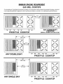
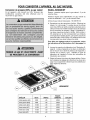
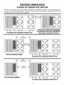
MINIMUMSPACINGREQUIREMENT
GAS GRILLCOOKTOPS
For installing a Triple Bay Downdraft Cooktop in combination with another Downdraft Cooktop, the mini-
mum spacing between adjacent units must be provided, as shown, for satisfactory performance.
\ /
Pk
\ /
/G\
PROSTYLE COOKTOP
4 3/8"
(11.1 cm)
ANY
(SINGLE, DOUBLE OR TRIPLE BAY
i 18"
(45.7 cm)
\/
I o.I
\/
--I/ .1
A 31 li
(11.1 cm)
\/
\I
/ok
\/
Ic,,
\I
ANY DOUBLE BAY
<
ANY SINGLE BAY
18"
(45.7 cm)
16 1/8"
(41 cm)
;I
%=,
PROSTYLE COOKTOP
\ /
/ok
\ /
S,,
\/
N:' N:' N:' ':iF _ ':ii"
PROSTYLE COOKTOP
10

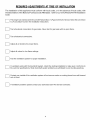
REQUIREDADJUSTMENTSATTIME OF INSTALLATION
The installation of this appliance must conform with local codes, or in the absence of local codes, with
the latest edition of the National Fuel Gas Code ANSI Z223.1 USA or current CAN/CGA-B149 Installation
Code.
This range was manufactu red for use with Natural Gas. If LP gas is the fuel of choice, follow the conversion
to LP procedure found in the installation instructions.
Test all external connections for gas leaks. Never test for gas leaks with an open flame.
Test all electrical connections.
Adjust all air shutters for proper flame.
Adjust all valves for low flame settings.
[_ Test the ventilation system for proper installation.
If a problem exists with the downdraft system, check the ducting installation to make sure it conforms to
the Jenn-Air specifications. Most downdraft system problems are attributed to poor ducting practices.
Contact your installer if the ventilation system will not remove smoke or cooking fumes from well trimmed
cuts of meat.
If ventilation problems persist contact your authorized Jenn-Air Service Contractor.
11

I_JENN-AIRI
403WESTFOURTHSTREET,NORTH° NEWTON,IA50208

Superficie convencional para
cocinar de gas con parrilla
Prostyle TM de modulo triple
Modelo JGD8348CDP
=JENN-AIR
403 WEST FOURTH STREET, NORTH • NEWTON, IA 5020
Las dimensiones se muestran en pulgadas y centimetros
AVlSO AL INSTALADOR: Deje estas instrucciones con el electrodomestico.
AVlSO AL CONSUMIDOR: Conserve estas instrucciones como referencia futura.
93/8"
23,81 cm
13_6"
34.11 cm
El ventilador puede
girarse para orientarlo
horizontal o vertical-
mente aflojando las
tuercas de la entrada del
ventilador.
Asequible desde adentro
de la ca.mara de
ventilacidn.
SELECCIONE EL CORTE
APROPIADO PARA EL DUCTO
(VEA LAS INSTRUCCIONES DE
INSTALACION DEL DUCTO).
VEA LA PAGINA 2
PARA
ENCONTRAR LAS
DIMENSIONES
DEL HUECO
t
15 13/16"
r40.16 cml
ESPACIO LIBRE
MINIMO
REQUERIDO
REGULADOR DE
/-- PRESION DEL
15•
ELECTRODOMESTICO
[,.38, 1 cm] J
- J 46 13/16" =J
3 13/16" 11118.90 cm]
[9.68 cm] _ NI' 'J_ll/ i_E
{ , I ' _'"--" "---"---"
e® ® ®®,,==e®
[14.60 cm]
REGULADOR ..3 5/16"
PARTS INFERIOR _ J _ DE PRESION 1 [8.41 cm]
OELATABLA.,4--1JI--I OELELEOTRO3/4"---- PARTE
DOMESTICO CADA INFERIOR
VENTILADOR _ I I _ CAJA DE EXTREMO DELDELA CAJA
I [ RECIPIENTE I CABLESCUBIERTADE QUEMADOR
l J DEDRENAJE j EXTREMO
DE LA CAJA
I _I 14" I 28 11/16 ° DEL
A_ [.35.56 cm] i [72.87 cm]-- QUEMADOR
INSTRUCCIONES PARA EL INSTALADOR:
• La dimensi6n "A" - proporciona 2" mfnimas (5.08 cm) de espacio libre del gabinete al
motor para fines de enfriamiento.
• NOTA" En donde sea posible, se recomiendan 6" (15.54 cm) para darle servicio al motor
y al ventilador.
• Espacio libre lateral: Las parrillas instaladas muy cerca de una pared deben tener un
espacio libre de 8" (20.32 cm) como mfnimo.
• Debe proporcionarse acceso para quitar y vaciar el recipiente de grasa.

RECORTES DEL GABINETE y DEL MOSTRADOR
E
45%"
9[ (116.2 cm) r
LfNEAS DE COMTE I _ 227/8'' Ref
(SOLAMENTE___ !_DEE __ (58.11 cm) r i
I
O
\
' t
(17.46-22 cm)
*Se recomiendan 8" (20.32 cm)
para los gabinetes a la medida.
Fm
NOTA: SE REQUIERE UN
PANEL INFERIOR DE CONTROL
S ESTA DIMENSION EXCEDE
5 3/4" (14.60 cm).
VE, LA P_,GINA 3 EN RELACION
AL REFUERZO DE LA PARTE
DELANTERA DEL GABINETE
GABINETE
(VISTADE FRENTE)
Vea las sugerencias de recorte 1-4 en la p_igina 6.
NOTA: Las toleranciasdelas dimensionesdel
huecoson de 1/16pulg (0.16cm)
Segt_n se requiera para la instalaci6n
(76.2 cm) 45%" t
(116.2 om)l 22%" Ref SI
r (58.11 era) r I
I
46 13/16"
(118.90 cm',
MOSTRADOR
_ E _oo
_o o_co
/ \
VISTADESDE
ARRIBA
\
QUITE LOS APOYOS DE LAS ESQUINAS
SEGON SEA NECESARIO
TiP. (4) HOJAS

Instalacion de gabinetes encima de la
parrilla Jenn-Air
El espacio libre horizontal mfnimo entre el borde del
electrodomestico y la construccidn combustible que se
extienda de la superficie para cocinar a 18" (45.7 cm) por
encima de la superficie para cocinar es:
1:" (4.45 cm) en la parte posterior
8" (20.32 cm) a los lados
NOTA: I_ste no es el espacio libre que se recomienda
sino el espacio libre mfnimo permitido.
%_____
Las Ifneas punteadas
indican la construccidn de
la campana de la estufa.
__
18"
(45._ c m)
8" --"1
(20.3 cm)
ESPACIO LIBRE MfNIMO
*A = 30" (76.2 cm) espacio libre mfnimo vertical entre
la superficie para cocinar y la construccidn
encima del electrodomestico.
B = 13" (33.02 cm) profundidad maxima de los
gabinetes instalados por encima de la superficie
para cocinar.
Trate de no usar los gabinetes que estAn encima de la
superficie para cocinar como espacios para almacenar ya
que asf eliminara los riesgos potenciales de tener que
atravesarse cuando haya llamas encendidas.
* Para eliminar el riesgo de quemaduras o incendios al
atravesarse por encima de las unidades calientes de la
superficie, debe evitarse el uso del espacio de
almacenamiento de los gabinetes Iocalizados encima
de las unidades de la superficie. Si los gabinetes se
van a usar para almacenamiento, el riesgo puede
reducirse usando una campana de estufa que
sobresalga horizontalmente cuando menos 5 pulgadas
(12.7 cm) de la parte inferior de los gabinetes.
Gabinetes encima de la superficie para
cocinar
La profundidad maxima de los gabinetes instalados por
encima de la superficie para cocinar es de 13 pulgadas
(33 cm).
PRECAUCION: ALGUNOS GABINETES
MATER!ALES DE CONSTRUCCION NO ESTAN
PRODUCIDO DURANTE LA OPERACION NORMAL
DEL ELECTRODOMC:STICO INDICADO, POR LO
TANTO PODRfA OCURRIR DECOLORACION O
DANOS, TALES COMO DESLAMINACION.

Instalacion del electrodomestico
En la Commonwealth de Massachusetts
Este producto debe instalarse por un plomero o un
instalador de gas certificado cuando estA instalado
dentro de la Commonwealth de Massachusetts.
Debe instalarse en el electrodomestico una vAIvula de
gas tipo "T" manual en la tuberfa del suministro de gas.
Cuando se utiliza un conector flexible de gas, no debe
exceder una Iongitud de tres (3) pies o 36 pulgadas
(91,4 cm).
Siga cuidadosamente las instrucciones adjuntas acerca
de los ductos.
Este electrodomestico estA diseSado para ventilarse
siempre hacia el exterior.
El recorte del mostrador, el recorte del frente del gabinete
y los huecos de los ductos deberAn prepararse de
acuerdo con las ilustraciones de las pAginas 1 y 2.
Instale el panel de control inferior en el fondo del recorte
del gabinete segen se muestra, usando los tornillos del
paquete de herrajes. (Figura 1).
Vista desde arriba
PANEL INFERIOR DE CONTROL
\
Figura 1
Coloque la unidad en el recorte del mostrador. El panel
principal de control debe sobreponerse a la parte superior
del panel inferior de control segQn se muestra. (Figura 2).
NOTA: En algunos estilos de gabinetes, podrfa ser
necesario tener que reforzar la parte delantera del
gabinete sujetando una abrazadera del frente a la parte
posterior del gabinete pot dentro desde debajo de la caja
del quemador.
Instale los ductos de acuerdo con las instrucciones
provistas. Los huecos de los ductos en el gabinete se
muestran en el dibujo de la pAgina 1. Haga las
conexiones electricas y de gas segOn se describe mAs
adelante en esta secci6n de instrucciones.
La instalaci6n de este electrodomestico debe estar en
conformidad con los c6digos locales, o si estos no
existieran, con la Qltima edici6n del C6digo Nacional de
Gas Combustible, ANSI Z.223.1 EE.UU. o el CODIGO
DE INSTALAClON actual CAN/CGA-B149.
El suministro electrico requerido es de 110/120-voltios,
C.A., 15 amp, 60 Hz. Este electrodomestico esta
equipado con un tipo de cord6n electrico conectado a
tierra. Debe proveerse un tomacorriente conectado a
tierra. Se recomienda, por comodidad, que este
tomacorriente se ubique en el Area que se muestra en la
ilustraci6n sombreada. Cuando se instale este
electrodomestico, debe conectarse a tierra de acuerdo
con los c6digos locales, o si estos no existieran, con la
Qltima edici6n del C6digo Nacional Electrico ANSI/NFPA
No. 70 EE.UU. o al Cddigo Canadiense Electrico CSA
STANDARD C22.1 parte 1.
El usuario puede experimentar la desconexi6n ocasional
del circuito siesta en uso el interruptor accionado por
corriente de perdida a tierra del circuito (GFCI).
10 1/16"
(25.56 cm)
4,
®® @ @@
46 13/16" (118.90 cm)
Para darle servicio a la superficie para
cocinar
Cuando se le de servicio a la superficie para cocinar es
necesario quitar la parte superior principal, antes de
quitar el panel de control.
PANEL INFERIOR DE
CONTROL
Figura 2

Conexion del electrodomestico al
suministro de gas
LA CONEXION AL SUMINISTRO DE GAS DEBE
REALIZARLA UN TI_CNICO CALIFICADO DE
SERVICIO O UN INSTALADOR DE ELECTRO-
DOMI_STICOS DE GAS. Las pruebas de fugas de gas
del electrodomestico las debe realizar el instalador de
acuerdo con las instrucciones proporcionadas.
Instale una valvula de cierre manual en un lugar accesible
en la tuberfa de gas de la parte exterior de este
electrodomestico para fines de abrir y cerrar el gas que
va al electrodomestico.
Haga la conexi6n de gas a la entrada del regulador de
presi6n del electrodomestico con una rosca de tuberfa
macho de 1/2". Use en las conexiones de la tuberfa un
compuesto para uniones de tuberfa aprobado que sea
resistente a la acci6n del gas butano. Pruebe todas las
uniones para asegurarse de que no haya fugas con una
soluci6n de agua y jab6n u otto medio aprobado de
detecci6n de fugas. Nunca pruebe las fugas con las
llamas encendidas.
PRECAUClON: LA GARANTiA QUEDA ANULADA EN
EL EQUlPO JENN-AIR CUANDO SE INSTALE PARA
OTRO FIN QUE NO SEA EL RECQMENDADO POR
EL FABRICANTE. DEBEN UTILIZARSE LAS TAPAS
DE PARED Y LAS TRANSICIONES RECOMENDA,
DAS PARA OBTENER UNA OPERACION E
INSTALACION CORRECTAS. ..............................
ADVERTENCIA
INSTRUCCIONES ELECTRICAS DE
CONEXION A TIERRA
ESTE ELECTRODOMI_STICO EST.& EQUIPADO
CON UNA CLAVIJA DE TRES PUNTAS DE
CONEXION A TIERRA PARA PROTEGERLO
CONTRA RIESGOS DE DESCARGAS Y DEBE
CONECTARSE DIRECTAMENTE EN UN
RECEPTACULO CORRECTAMENTE CONECTADO
A TIERRA. NO CORTE NI QUITE LA PUNTA DE
TIERRA DE ESTA CLAVIJA.
Ajuste del obturador de aire
Este electrodomestico se embarca de fabrica con los
obturadores de aire ajustados para usarse con gas
natural. Si es necesario ajustarlos mas o reajustarlos para
usarse con gas butano, ajuste los obturadores de aire del
modo siguiente:
Obturadores de aire de cartucho del
quemador de la parrilla y del quemador
de la superficie para cocinar
(Yea las ilustraciones "A" y "B")
El obturador de aire del lado izquierdo controla la mitad
posterior de los quemadores. El obturador de aire del lado
derecho controla la mitad delantera. Los obturadores de aire
del cartucho del quemador de la superficie se acceden a
traves de las aberturas en la parte inferior de la caja del
cartucho.
Deslice los obturadores de aire hacia atras o hacia adelante
para aumentar o reducir el tamafio de la abertura del aire.
Los obturadores quedan muy bien ajustados, asf que podrfa
ser necesario tener que usar la hoja de un destornillador o
unas pinzas con punta de aguja para hacer este ajuste (vea
la ilustraci6n).
Observe los cambios en la apanencia de la llama conforme
mueve el obturador de aire. El ajuste es aceptable cuando
aparece una llama claramente definida, azul y uniforme en
el ajuste mas alto de la llama. El buen ajuste del obturador
de aire garantiza que permanezca correctamente colocado.
Obturador de aire del quemador de la parrilla y
quemador de la superficie para cocinar
f est,. equipado)
.to
.._ _'_/bZ_-,, (PARA
,
ABERTURA _ /_j#_,_ ",,T_,_-'_
DEL AIRE "_/_ "_ "_ (PARA
OBTAUIR#DOR "- L,Z_ CERRAR)
DE AIRE INSERTE LA HOJA DE UN DES-
TORNILLADOR EN LA RANURA Y
GIRE EJERCIENDO UNA PRESION
LEVE PARA PERMITIR QUE EL
OBTURADOR DE AIRE SE
DESLICE CON FACILIDAD
Ilustracidn "A"
En cualquier quemador, el cerrar demasiado el obturador de
aire hara que la llama se vuelva suave y con punta amarilla.
Abrir demasiado el obturador de aire hara que la llama se
separe de los puertos del quemador. El ajuste correcto
producira una llama claramente definida, azul y uniforme.
OBTURADOR
DE AIRE
Ilustracidn "B"

Sugerencias importantes de
instalacion
1. Achaflane todos los bordes expuestos del laminado
decorativo para evitar daSos pot desportilladuras.
2. Haga radiales en las esquinas de los recortes y Ifjelas
para asegurarse que los bordes queden lisos y evitar
que se quiebren las esquinas.
3. Los bordes disparejos, las esquinas interiores que no
se han redondeado y los ajustes forzados pueden
contribuir a que se quiebre el laminado del mostrador.
4. El mostrador debe estar apoyado a 31 (7.6 cm) del
recorte.
En cualquier quemador, cerrar demasiado el
obturador de aire hara que la llama se vuelva suave y
de punta amarilla. Abrir demasiado el obturador de
aire hara que la llama se separe de los puertos del
quemador. El ajuste correcto producira una llama
claramente definida, azul y uniforme.
Ajuste de llama baja
(Vea la ilustraci6n "C")
Este electrodomestico se embarca de fabrica con ajustes
de llama bajo y medio para usarse con gas natural• Si son
necesarios ajustes adicionales, o para reajustarlo para
usarse con gas butano, continQe del modo siguiente:
1. Encienda el quemador y coloque la perilla de control en
la llama baja.
2. Quite la perilla de control del vastago de la valvula.
PRECAUCION: NUNCA USE UNA.HOJA METALICA
PARA SACAR LA PERILLAI SIESTA NO PUEDE
SACARSE CON FACILIDAD, INTRODUZCA UN
SECADOR DOBLADO DE TELA POR DEBAJO DE LA
PERILLA Y TIRE DEL SECADOR HACIA ARRIBA
EJERCIENDO UNA PRESION UNIFORME.
3. Inserte un destornillador de hoja delgada y plana dentro
del receso al centro del vastago de la valvula y
enganche la hoja en la ranura en el tornillo de ajuste.
4. Gire el tornillo de ajuste del centro del vastago para
ajustar el tamaSo de la llama•
•.. en el sentido de las manecillas del reloj para
reducirla.
•.. en sentido contrario al de las manecillas del reloj
para aumentarla.
5. Coloque de nuevo la perilla de control cuando termine
el ajuste.
Un ajuste apropiado producira una llama estable, uniforme
en color azul de tamaSo mfnimo. El ajuste final debe
revisarse girando la perilla de alto a bajo varias veces sin
apagar la llama•
Este ajuste, en el ajuste bajo, proporcionara
automaticamente el tamaSo correcto de llama para el
ajuste medio.
Ilustraci6n "C"
EN EL SENTIDO DE LAS
MANECILLAS DEL RELOJ
PARA REDUCIR EL
I1 TAMANO DE LA LLAMA
EN SENTIDO CONTRARIO AL
DE LAS MANECILLAS DEL
RELOJ PARA AUMENTAR EL
TAMAI_IO DE LA LLAMA
Prueba de presion
La presi6n maxima de suministro de gas para el regulador
de presi6n del electrodomestico proporcionado con este
electrodomestico es de 141 W.C. La presi6n de prueba
para revisar el regulador de presi6n del electrodomestico
debe ser cuando menos de 61 W.C. para gas natural, y
cuando menos de 111 W.C. para gas butano. Se embarca
de fabrica ajustado para usarse con gas natural a 51 W.C.
Este electrodomestico y su valvula de cierre individual
deben estar desconectados del sistema de tuberfa de
suministro de gas durante las pruebas de presi6n a
presiones de prueba por encima de 1/21 PSlG (3.5 k Pa).
Este electrodomestico debe estar aislado del sistema de
tuberfa del suministro de gas cerrando la valvula de cierre
individual durante las pruebas de presi6n del sistema de
tuberfa de suministro de gas a presiones de prueba
iguales o menores de 1/21 PSlG (3.5 k Pa).
Conversion del regulador de presion
del electrodomestico
(Yea la ilustraci6n "D")
Esta unidad se suministra con un regulador de presi6n para
electrodomesticos Maxitrol. Siga las instrucciones de la
ilustraci6n "D".
R DE PRESION PARA
REGULADO
ELECTRODOMI_STICOS MAXITROL
CONVERTIDO_ LP
TAPA Y I
_SADOR .]
NAT--'_t , ..i,,,,°_"
i../ !
APLIQUE PRESION HACIA ABAJO CON
EL DEDO EN LOS BORDES DEL DISCO
PARA VOLVER A COLOCAR EL
PASADOR EN LA TAPA
APLIQUE
T_-_- PRESlON
LATERAL CON
EL DEDO PARA
!
NA QUITAR EL I LP
PASADOR DE
LA TAPA
Ilustraci6n "D"
Aviso de altitud
Las capacidades de funcionamiento especificadas del
quemador de gas por Io general corresponden a elevaciones
de hasta 609.6 metros (2000 pies). Cuando la altitudes
mayor, podria ser necesario reducir las capacidades de
funcionamiento para Iograr un funcionamiento satisfactorio.
Un tecnico local, certificado en servicios de gas, podrA
aconsejarle si es necesaria la reducci6n.

Conversion a gas butano
Este electrodomestico se embarca de fabrica equipado
para usarse con gas natural. Para convertirlo de gas
natural a gas butano, realice los pasos 1 al 4.
1. Quite las campanas de orificio de gas natural. Instale
las campanas adjuntas de orificio codificadas pot color.
Se encuentran en un paquete que esta sujeto en el
area impelente externa de este electrodomestico.
(Vea la ilustraci6n "E", mas adelante, y las
instrucciones de conversi6n a gas butano de la
pagina 8).
2. Invierta la tapa en el regulador de presi6n convertible
(siesta equipado) Iocalizado en la entrada del mQItiple
de gas.
3. Ajuste los obturadores de aire en los quemadores
individuales para obtener la apariencia correcta de la
llama.
4. Coloque el ajuste bajo de llama en cada quemador
girando el tornillo de ajuste en el centro del vastago de
la valvula.
Para realizar estos ajustes de conversi6n siga las
instrucciones y las ilustraciones ("A" a la "E", en las
paginas 5-7).
Este electrodomestico se embarca de fabrica con
campanas de orificio para usarse con gas natural. Para
convertirlo de gas natural a gas butano, coloque una Ilave
espafiola de 1/21 a la secci6n hexagonal de la campana
de orificio. Gire en sentido contrario al de las manecillas
del reloj para quitarla. Conserve las campanas de orificio
de gas natural que quit6 del electrodomestico para usarlas
en el futuro. Instale las campanas suministradas de
orificio codificadas pot color. (Vea las instrucciones de
conversi6n a gas butano anteriores yen la pagina 8). Gire
en el sentido de las manecillas del reloj para instalarla.
Mantenga la dimensi6n especificada en la ilustraci6n "E".
LLAVE
ESPANOLA DE
1/21
GIRE EN SENTIDO
CONTRARIO AL DE LAS
MANECILLAS DEL RELOJ
PARA QUITARLA
GIRE EN EL
SENTIDO DE LAS
MANECILLAS DEL
RELOJ
PARA APRETARLA
CAMPANA DE ORIFICIO
Ilustraci6n "E"
Aplique un Iiquido anticorrosivo detector de fugas en
todas las uniones y accesorios de la conexi6n de gas
entre la valvula de cierre de la tuberia de suministro y
la estufa. Incluya los accesorios de gas y las uniones
de la estufa si las conexiones se alteraron durante la
instalaci6n. Revise si hay fugas. Las burbujas que
aparezcan alrededor de los accesorios y las
conexiones indicaran que hay fugas. Si aparece una
fuga, cierre la valvula de la tuberia de suministro de
gas, apriete las conexiones, abra la valvula de cierre
de la tuberia de suministro de gas, y vuelva a revisar
si hay fugas. Nunca realice pruebas de fugas con la
llama encendida.
ADVERTENCIA
Puede occurrir un escape de gas en su sistema y
provocar una situaci6n peligrosa. Los escapes de gas no
pueden set detectados pot olor solamente. Los
proveedores de gas recomiendan que compare e instale
un detector de gas aprobabo pot el laboratorio UL. Inst
lelo y uselo do acuerdo con las instrucciones del
favricante.
Ajustes de control
El tamafio y tipo de recipientes de cocina y la cantidad y
tipo de alimentos que se cocinen influiran en el ajuste que
se necesita para obtener los mejores resultados de
cocci6n. El ajuste indicado debera servir como una guia
mientras se familiariza con la superficie para cocinar.
Use el ajuste de llama HI (alto)
para hacer que los alimentos
hiervan rapidamente o para
comenzar una operaci6n de
cocci6n. Luego reduzca el ajuste
para continuar el cocimiento.
Nunca desatienda los alimentos
cuando esten en el ajuste de
llama HI (alto).
El ajuste Med (medio) se usa
para continuar una operaci6n de
cocci6n. Los alimentos no se
cocinaran mas rapido cuando se
usa el ajuste de llama HI (alto)
que con el que se necesita para
mantener un hervor suave.
Recuerde, el agua hierve a la
misma temperatura aunque
hierva suave o vigorosamente.
II
Use el ajuste LO (bajo) para
mantener los alimentos a
temperatura de servir sin que se
sigan cocinando. Se data cuenta
que podria haber un poco de
cocci6n adicional si el recipiente
se encuentra tapado.
I

PARACONVERTIREL ELECTRODOMI_STICOPARAUSARSECON GAS BUTANO
Instruccionesde conversi6nde gas naturala gas butano (LP)
Modelos- JGD8348CDP
MQItiple _resi6n necesaria del gas butano - 10" W.C.
Presidn necesaria de entrada del gas butano al regulador
de presidn del electrodomestico - 11" - 12" W.C.
Las campanas de orificio de conversi6n se adjuntan con
este modelo.
Entrada de gas butano especificada - 46,000 BTU/hora.
JGD8348CDP
QUEMADOR BTU/hora ORIFICIO PULGADAS COLOR
Izquieroposterior(IP) 7500 #66 .033 Zinc
Izquierdodelantero(ID) 7500 #66 .033 Zinc
Centroposterior(CP) 6500 #68 .031 Rojo
Centrodelantero(CD) 9000 #63 .037 Azul
Derechoposterior(DP) 6500 #68 .031 Rojo
Derechodelantero(DD) 9000 #63 .037 Azul
La page est en cours de chargement...
La page est en cours de chargement...
La page est en cours de chargement...
La page est en cours de chargement...
La page est en cours de chargement...
La page est en cours de chargement...
La page est en cours de chargement...
La page est en cours de chargement...
La page est en cours de chargement...
La page est en cours de chargement...
La page est en cours de chargement...
La page est en cours de chargement...
La page est en cours de chargement...
La page est en cours de chargement...
La page est en cours de chargement...
La page est en cours de chargement...
-
 1
1
-
 2
2
-
 3
3
-
 4
4
-
 5
5
-
 6
6
-
 7
7
-
 8
8
-
 9
9
-
 10
10
-
 11
11
-
 12
12
-
 13
13
-
 14
14
-
 15
15
-
 16
16
-
 17
17
-
 18
18
-
 19
19
-
 20
20
-
 21
21
-
 22
22
-
 23
23
-
 24
24
-
 25
25
-
 26
26
-
 27
27
-
 28
28
-
 29
29
-
 30
30
-
 31
31
-
 32
32
-
 33
33
-
 34
34
-
 35
35
-
 36
36


Jenn-Air JGD8348CDP17 Guide d'installation
- Catégorie
- Cuisinières
- Taper
- Guide d'installation
dans d''autres langues
Documents connexes
-
Jenn-Air Ventilation Hood JGD8348CDP Manuel utilisateur
-
-
-
-
-
-
-
-
-