Empire Heating Systems UltraSaver90Plus Deep Rear Shroud Kit Le manuel du propriétaire
- Taper
- Le manuel du propriétaire

37848-0-0117 Page 1
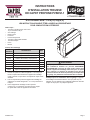
INSTALLATION
INSTRUCTIONS PVSDS1-1
DEEP SHROUD KIT
FOR USE ON: PVS(18,35)(N,P)
INSTRUCTIONS MUST BE LEFT WITH THE OWNER FOR FUTURE REFERENCE.
Tools Needed:
• 5/16” Nut Driver 10”+ or Socket with Extension
• Masking or Painter’s Tape
• Drill
• Masonry Drill Bit
• Standard Flat Screwdriver
• Phillips Screwdriver
• Pliers
• Level
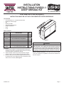
Carton Contents:
PART
NUMBER
DESCRIPTION QTY
31557 Deep Rear Shroud 1
31556 Pipe Stop Bracket 1
32179 Vent Transition Box, Deep Shroud 1
32326 Flue Support Bracket 1
R11567 Intake Connector Gasket 1
R11737 Hose Clamp 1
R3580 #8-18 x 1/2 Phillips Truss Head Screws 6
32642 1” x 1-1/2” White Fiberfrax Spacer 1
Figure 1
WARNING
The deep rear shroud is for use in oor mounted installations
ONLY! DO NOT use the Deep Rear Shroud kit for mounting
the wall furnace in an off the oor, wall mounted installation.
If the wall furnace needs to be installed above oor level, as
in a garage, an elevated platform will need to be constructed.
Note for Garage Installations: The wall furnace must be raised
15-1/2”offoftheooronaplatformtomeetthe18”minimumoff
theoorrequired.
Installation
1. Removethefour#10x1/2”hex-headscrewssecuringthe
standard rear shroud to the wall furnace and remove the rear
shroud.Discardthestandardrearshroud.
2. Attachthedeeprearshroudtothewallfurnaceusingthe
samefour#10x1/2”hex-headscrewsremovedinstep1.
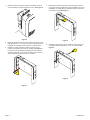
3. Movethewallfurnaceintopositionagainstthewall,ensure
thewallfurnaceislevel.Adjustthelegsonthebottomofthe
wallfurnaceifnecessary.See Figure 1.

37848-0-0117Page 2
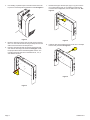
4. Usemaskingorpainter’stapetomarkthelocationofthetwo
topcornersofthedeepshroudagainstthewall.See Figure 2.
Figure 2
5. Movethewallfurnaceawayfromthewall.Removethefour
#10 x 1/2” hex-head screws securing the deep shroud to the
wallfurnaceandremovethedeepshroud.
6, Place the deep shroud back into position against the wall
andmarkthemountingholelocations.See Figure 3. Drill
thepropersizedholesfortheeldsuppliedanchors.The
mounting holes are sized to accommodate 3/16”, 1/4”, or
3/8”diameteranchors.
Figure 3
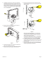
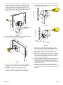
7. Determineuepipedirection(left,right,orup)andremove
thecorrespondingknockout.Ifinstallingthewallfurnace
inadirectventconguration,removebothknockouts.See
Figure 4.
Figure 4
8. Installtheuesupportbracketusingtwo#8-18x1/2Phillips
headscrewsprovided.See Figure 5.
Figure 5

37848-0-0117 Page 3
9. Ifinstallingthewallfurnaceinadirect-ventconguration,
assemble the pipe stop bracket to the inside of the air box
and install the blue intake connector gasket to the vent tran-
sitionbox.Attachtheventtransitionboxtotherearshroud
usingtwo#8-18x1/2Phillipsheadscrewsprovided.Make
sure that the vent transition box opening is aligned with the
knockout.See Figure 6.
NOTE ORIENTATION
OF BRACKET.
Figure 6
10. Securethedeepshroudinplaceonthewallusingfour
eld-suppliedanchors.See Figure 7.
Figure 7
11. Installthegassupplylinetothewallfurnacefollowingthe
wallfurnace’sinstallationinstructions.
12. Refertotheventingsectionofthewallfurnace’sinstallation
instructionsandruntheventpipetotherearshroud.
13. Securethe90degreeelbowinsideofthedeepshroudto
theuesupportbracketusingthehoseclampprovided.See
Figures 8 and 9.
Figure 8
Figure 9
Makesurethattheueterminates11/2”fromtheendof
thesupportbracket.See Figure 8. For PVC a short piece
of pipe will need to be used as an extension, the Poly-Pro
elbownoextensionwillbeneeded.
If using Poly-Pro piping, place the white 1” x 1-1/8” pad pro-
videdbetweentheelbowandtheuesupportbracketprior
toinstallingandtighteningthehoseclamp.See Figure 9.
14. IfInstallingthewallfurnaceinadirect-ventconguration,
insert the intake air pipe through the shroud and into the vent
transitionbox.Makesurethatthepipeisfullyupagainstthe
pipestopbracket.
15. Installcondensationdrainandsecurethewallfurnacetothe
deep shroud following the venting section of the installation
instructionsprovidewiththewallfurnace.

37848-0-0117Page 4
www.empirecomfort.com
Empire Comfort Systems Inc.
Belleville, IL
Ifyouhaveageneralquestion
about our products, please e-mail
usat[email protected].
If you have a service or repair
question,pleasecontactyourdealer.

37848-0-0117 Page 1
LES INSTRUCTIONS DOIVENT ÊTRE LAISSÉES AU PROPRIÉTAIRE
POUR CONSULTATION ULTÉRIEURE.
Outils requis :
• Tournevis à douille 5/16 po d’au moins
10 po ou douille 5/16 po
• avec rallonge
• Ruban cache
• Perceuse
• Foret de maçonnerie
• Tournevis à lame plate standard
• Tournevis Phillips
• Pince
• Niveau
Contenu de l’emballage
NUMÉRO
DE PIÈCE
DESCRIPTION QTÉ
31557 Capot arrière profond 1
31556 Support d’arrêt de tuyau 1
32179 Caisson de transition, capot profond 1
32326 Support de tuyau de fumée 1
R11567 Joint du connecteur d’admission 1
R11737 Collier de serrage 1
R3580 Vis Phillips à tête bombée n
o
8-18 x 1/2 po 6
32642 Espaceur Fiberfrax blanc 1 x 1-1/2 po 1
Figure 1
AVERTISSEMENT
Le capot profond arrière est destiné à une utilisation sur
des installations montées sur plancher SEULEMENT!
N’UTILISEZ PAS la trousse de capot arrière profond pour
monter l’appareil de chauffage mural sans qu’il ne repose
sur le plancher. Si l’appareil de chauffage mural doit être
installé au-dessus du niveau du plancher, par exemple dans
un garage, une plateforme surélevée doit être construite.
Remarque pour les installations dans un garage : L’appareil
dechauffagemuraldoitêtreélevéà15-1/2po(394mm)du
plancher sur une plateforme pour satisfaire la distance minimale
requisede18po(457mm)depuisleplancher.
Installation
1. Enleverlesquatrevisàtêtehexagonalen
o
10x1/2poqui
xentlecapotarrièrestandardsurl’appareildechauffage
muraletenleverlecapotarrière.Sedépartirducapotarrière
standard.
2. Fixerlecapotarrièreprofondàl’appareildechauffageen
utilisant les vis à tête hexagonale n
o
10 x 1/2 po enlevées à
l’étape1.
3. Placerl’appareildechauffagemuralenposition
contrelemur,ens’assurantqu’ilestdeniveau.Régler
lespiedsdanslebasdel’appareilsinécessaire.
INSTRUCTIONS
D’INSTALLATION TROUSSE
DE CAPOT PROFOND PVSDS1-1
À UTILISER SUR : PVS(18,35)(N,P)

37848-0-0117Page 2
4. Utiliserduruban-cachepourmarquerlapositiondesdeux
coinssupérieursducapotprofondsurlemur.Voir Figure 2.
Figure 2
5. Déplacerl’appareilàl’écartdumur.Enleverlesquatrevisà
tête hexagonale n
o
10x1/2poquixentlecapotprofondsur
l’appareildechauffagemuraletenleverlecapotprofond.
6. Replacerlecapotprofondenpositioncontrelemuret
marquerlespositionsdestrousdemontage.Voir Figure 3.
Percer des trous de diamètre approprié pour les ancrages
achetéslocalement.Lestrousdemontagedevrontrecevoir
desancragesdediamètres3/16,1/4ou3/8po.
Figure 3
7. Déterminerladirectiondutuyaudefumée(gauche,droite
ouhaut)etenleverladébouchurecorrespondante.Pourune
installationencongurationàventilationdirecte,enleverles
deuxdébouchures.Voir Figure 4.
Figure 4
8. Installerlesupportdetuyaudecheminéeàl’aidedesdeux
vis Phillips à tête hexagonale n
o
8-18x1/2fournies.Voir
Figure 5.
Figure 5

37848-0-0117 Page 3
9. Pouruneinstallationencongurationàventilationdirecte,
monter le support d’arrêt de tuyau sur l’intérieur du caisson
d’airetposerlejointduconnecteurd’admissionbleusurle
caissondetransition.Fixerlecaissondetransitionsurle
capot arrière à l’aide des deux vis à tête Phillips n
o
8-18 x 1/2
fournies.S’assurerquel’oriceducaissondetransitionest
alignésurladébouchure.Voir Figure 6.
NOTE ORIENTATION
OF BRACKET.
Figure 6
10. Fixerlecapotprofondenplacesurlemuràl’aidedesquatre
ancragesachetéslocalement.Voir Figure 7.
Figure 7
11. Installerlaconduited’alimentationengazsurl’appareilde
chauffage mural en suivant les instructions d’installation de
l’appareil.
12. Sereporteràlasectionsurlaventilationdansles
instructions d’installation de l’appareil de chauffage et
acheminerletuyaudeventilationjusqu’aucapotarrière.
13. Fixerlecoudeàangledroitàl’intérieurducapotprofondsur
le support de tuyau de fumée à l’aide du collier de serrage
fourni.Voir les Figures 8 et 9.
Figure 8
Figure 9
S’assurerqueletuyaudefuméesetermineà1-1/2po
(38mm)del’extrémitédusupport.Voir Figure 8. Pour le
PVC, un petit segment de tuyau devra servir de rallonge;
dans le cas du coude Poly-Pro aucune rallonge n’est
nécessaire.
Dans le cas d’une tuyauterie Poly-Pro, placer le coussinet
blanc de 1 x 1-1/8 po fourni entre le coude et le support de
tuyau de fumée avant d’installer et de serrer le collier de
serragedetuyau.Voir Figure 9.
14. Pouruneinstallationdel’appareildechauffagemuraldans
unecongurationàventilationdirecte,insérerletuyau
d’admission d’air à travers le capot et dans le caisson de
transition.S’assurerqueletuyauestbienappuyécontrele
supportd’arrêtdetuyau.
15. Installerledraindecondensationetxerl’appareilde
chauffage sur le capot profond en se reportant à la section
sur la ventilation des instructions d’installation fournies avec
l’appareil.
NOTERL’ORIENTATION
DUSUPPORT
COUSSINET
BLANC

37848-0-0117Page 4
www.empirecomfort.com
Empire Comfort Systems Inc.
Belleville, IL
Pourtoutequestiongénérale
concernant nos produits, veuillez nous
envoyeruncourrielà[email protected].
Pourtoutequestiond’entretienoude
réparation,veuillezcontactervotrerevendeur.
-
 1
1
-
 2
2
-
 3
3
-
 4
4
-
 5
5
-
 6
6
-
 7
7
-
 8
8


Empire Heating Systems UltraSaver90Plus Deep Rear Shroud Kit Le manuel du propriétaire
- Taper
- Le manuel du propriétaire
dans d''autres langues
Documents connexes
-
Empire Heating Systems UltraSaver90Plus Condensate Hose Kit Le manuel du propriétaire
-
-
-
-
-
-
-
-
-