
N-Tron
®
Series
300 Series
Media Converter & Industrial Ethernet Switches
Installation Guide | December 2015

COPYRIGHT
Copyright, © 2015 Red Lion Controls, Inc.
20 Willow Springs Circle
York, PA 17406
All rights reserved. Red Lion, the Red Lion logo and N-Tron are registered trademarks of Red Lion Controls,
Inc. All other company and product names are trademarks of their respective owners.
CONTACT INFORMATION :
AMERICAS
York, PA: +1 (717) 767-6511
Mobile, AL: +1 (251) 342-2164
Ballston Lake, NY: +1 (518) 877-5173
Hours: 8am-6pm Eastern Standard Time
(UTC/GMT -5 hours)
ASIA-PACIFIC
Shanghai, P.R. China: +86 21-6113-3688 x767
Hours: 10am-6pm China Standard Time
(UTC/GMT +8 hours)
EUROPE
The Netherlands: +31 33-4723-225
Hours: 9am-6pm Central European Time
(UTC/GMT +1 hour)
Website: www.redlion.net
Email: [email protected]

N-Tron® 300 Series Hardware Guide i
Table of Contents Revised 2015-12-04
Table of Contents
Preface . . . . . . . . . . . . . . . . . . . . . . . . . . . . . . . . . . . . . . . . . . . . . . . . . . . . . . . . . . . . . . . . . . . . . . . . . . . . . . . iii
Disclaimer . . . . . . . . . . . . . . . . . . . . . . . . . . . . . . . . . . . . . . . . . . . . . . . . . . . . . . . . . . . . . . . . . . . . . . . . . . iii
Compliance Information . . . . . . . . . . . . . . . . . . . . . . . . . . . . . . . . . . . . . . . . . . . . . . . . . . . . . . . . . . . . . . iii
Part 15 of the Federal Communications Commission (FCC) - A Rules: Interference . . . . . . . . iii
Industry Canada . . . . . . . . . . . . . . . . . . . . . . . . . . . . . . . . . . . . . . . . . . . . . . . . . . . . . . . . . . . . . . iii
Environmental Impact Statement . . . . . . . . . . . . . . . . . . . . . . . . . . . . . . . . . . . . . . . . . . . . . . . . iv
Toxic Emissions . . . . . . . . . . . . . . . . . . . . . . . . . . . . . . . . . . . . . . . . . . . . . . . . . . . . . . . . . . . . . . . iv
Trademark Acknowledgments . . . . . . . . . . . . . . . . . . . . . . . . . . . . . . . . . . . . . . . . . . . . . . . . . . . . . . . . . iv
Applicable 300 Series Industrial Ethernet Switches . . . . . . . . . . . . . . . . . . . . . . . . . . . . . . . . . . . . . . . . iv
Release Notes and Document Updates . . . . . . . . . . . . . . . . . . . . . . . . . . . . . . . . . . . . . . . . . . . . . . . . . . iv
Publication History . . . . . . . . . . . . . . . . . . . . . . . . . . . . . . . . . . . . . . . . . . . . . . . . . . . . . . . . . . . . iv
Related Documents . . . . . . . . . . . . . . . . . . . . . . . . . . . . . . . . . . . . . . . . . . . . . . . . . . . . . . . . . . . . v
Document Comments . . . . . . . . . . . . . . . . . . . . . . . . . . . . . . . . . . . . . . . . . . . . . . . . . . . . . . . . . . v
Additional Product Information . . . . . . . . . . . . . . . . . . . . . . . . . . . . . . . . . . . . . . . . . . . . . . . . . . . . . . . . v
Warnings and Cautions / Avertissements et mises en garde . . . . . . . . . . . . . . . . . . . . . . . . . . . . . . . . . v
General Safety Cautions and Warnings / Précautions et avertissements
de sécurité générale . . . . . . . . . . . . . . . . . . . . . . . . . . . . . . . . . . . . . . . . . . . . . . . . . . . . . . . . v
Electrical Safety Warnings / Avertissements de sécurité électrique . . . . . . . . . . . . . . . . . . . . . vi
Environmental Safety Cautions and Warnings / Sécurité environnementale
mises en garde et avertissements . . . . . . . . . . . . . . . . . . . . . . . . . . . . . . . . . . . . . . . . . . . . . vi
Hazardous Location Warnings / Les avertissements d'emplacement dangereux. . . . . . . . . . vii
Laser Safety Waning / Consignes de sécurité relatives au laser. . . . . . . . . . . . . . . . . . . . . . . . viii
Introduction and Specifications . . . . . . . . . . . . . . . . . . . . . . . . . . . . . . . . . . . . . . . . . . . . . . . . . . . . . . . . . 1-1
Introduction . . . . . . . . . . . . . . . . . . . . . . . . . . . . . . . . . . . . . . . . . . . . . . . . . . . . . . . . . . . . . . . . . . . . . . 1-1
302MC/MCE . . . . . . . . . . . . . . . . . . . . . . . . . . . . . . . . . . . . . . . . . . . . . . . . . . . . . . . . . . . . . . . 1-1
304TX, 306TX, and 308TX . . . . . . . . . . . . . . . . . . . . . . . . . . . . . . . . . . . . . . . . . . . . . . . . . . . . . 1-1
305FX and 306FX2 . . . . . . . . . . . . . . . . . . . . . . . . . . . . . . . . . . . . . . . . . . . . . . . . . . . . . . . . . . . 1-1
305FXE and 306FXE2 . . . . . . . . . . . . . . . . . . . . . . . . . . . . . . . . . . . . . . . . . . . . . . . . . . . . . . . . . 1-1
Key Features . . . . . . . . . . . . . . . . . . . . . . . . . . . . . . . . . . . . . . . . . . . . . . . . . . . . . . . . . . . . . . . . . . . . . . 1-1
300 Series Specifications . . . . . . . . . . . . . . . . . . . . . . . . . . . . . . . . . . . . . . . . . . . . . . . . . . . . . . . . . . . . 1-2
Regulatory Approvals . . . . . . . . . . . . . . . . . . . . . . . . . . . . . . . . . . . . . . . . . . . . . . . . . . . . . . . . . . . . . . 1-3
Safety . . . . . . . . . . . . . . . . . . . . . . . . . . . . . . . . . . . . . . . . . . . . . . . . . . . . . . . . . . . . . . . . . . . . . 1-3
EMI . . . . . . . . . . . . . . . . . . . . . . . . . . . . . . . . . . . . . . . . . . . . . . . . . . . . . . . . . . . . . . . . . . . . . . . 1-3
EMS . . . . . . . . . . . . . . . . . . . . . . . . . . . . . . . . . . . . . . . . . . . . . . . . . . . . . . . . . . . . . . . . . . . . . . 1-3
Conducted Low Frequency: IEC60533 . . . . . . . . . . . . . . . . . . . . . . . . . . . . . . . . . . . . . . . . . . . 1-3
Shock: IEEE 1613 (250 mm) . . . . . . . . . . . . . . . . . . . . . . . . . . . . . . . . . . . . . . . . . . . . . . . . . . . 1-3

Table of Contents Revised 2015-12-04
ii N-Tron® 300 Series Hardware Guide
Vibration . . . . . . . . . . . . . . . . . . . . . . . . . . . . . . . . . . . . . . . . . . . . . . . . . . . . . . . . . . . . . . . . . . 1-3
Cold: IEC60068-2-1 . . . . . . . . . . . . . . . . . . . . . . . . . . . . . . . . . . . . . . . . . . . . . . . . . . . . . . . . . . 1-3
Dry Heat: IEC60068-2-2 . . . . . . . . . . . . . . . . . . . . . . . . . . . . . . . . . . . . . . . . . . . . . . . . . . . . . . 1-3
Damp Heat: IEC60068-2-30 (Test Db) . . . . . . . . . . . . . . . . . . . . . . . . . . . . . . . . . . . . . . . . . . . 1-3
Certifications . . . . . . . . . . . . . . . . . . . . . . . . . . . . . . . . . . . . . . . . . . . . . . . . . . . . . . . . . . . . . . . . . . . . . 1-3
Installation . . . . . . . . . . . . . . . . . . . . . . . . . . . . . . . . . . . . . . . . . . . . . . . . . . . . . . . . . . . . . . . . . . . . . . . . . . 2-5
Introduction . . . . . . . . . . . . . . . . . . . . . . . . . . . . . . . . . . . . . . . . . . . . . . . . . . . . . . . . . . . . . . . . . . . . . . 2-5
Unpacking . . . . . . . . . . . . . . . . . . . . . . . . . . . . . . . . . . . . . . . . . . . . . . . . . . . . . . . . . . . . . . . . . . . . . . . . 2-5
Inspection . . . . . . . . . . . . . . . . . . . . . . . . . . . . . . . . . . . . . . . . . . . . . . . . . . . . . . . . . . . . . . . . . . . . . . . . 2-5
Installing/Mounting . . . . . . . . . . . . . . . . . . . . . . . . . . . . . . . . . . . . . . . . . . . . . . . . . . . . . . . . . . . . . . . . 2-5
DIN-Rail Mounting . . . . . . . . . . . . . . . . . . . . . . . . . . . . . . . . . . . . . . . . . . . . . . . . . . . . . . . . . . 2-7
Connections . . . . . . . . . . . . . . . . . . . . . . . . . . . . . . . . . . . . . . . . . . . . . . . . . . . . . . . . . . . . . . . . . . . . . . 2-8
Power Connection . . . . . . . . . . . . . . . . . . . . . . . . . . . . . . . . . . . . . . . . . . . . . . . . . . . . . . . . . . . 2-8
Ground Connection . . . . . . . . . . . . . . . . . . . . . . . . . . . . . . . . . . . . . . . . . . . . . . . . . . . . . . . . . . 2-9
300 Series Grounding Techniques . . . . . . . . . . . . . . . . . . . . . . . . . . . . . . . . . . . . . . . . . . . . . . 2-9
RJ45 Connector Crimp Specifications . . . . . . . . . . . . . . . . . . . . . . . . . . . . . . . . . . . . . . . . . . . . . . . . . 2-10
Connecting the Unit . . . . . . . . . . . . . . . . . . . . . . . . . . . . . . . . . . . . . . . . . . . . . . . . . . . . . . . . . . . . . . 2-10
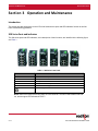
Operation and Maintenance . . . . . . . . . . . . . . . . . . . . . . . . . . . . . . . . . . . . . . . . . . . . . . . . . . . . . . . . . . 3-11
Introduction . . . . . . . . . . . . . . . . . . . . . . . . . . . . . . . . . . . . . . . . . . . . . . . . . . . . . . . . . . . . . . . . . . . . . 3-11
300 Series Ports and Indicators . . . . . . . . . . . . . . . . . . . . . . . . . . . . . . . . . . . . . . . . . . . . . . . . . . . . . 3-11
300 Series LED’s and Operating Modes . . . . . . . . . . . . . . . . . . . . . . . . . . . . . . . . . . . . . . . . . . . . . . . 3-12
Maintenance . . . . . . . . . . . . . . . . . . . . . . . . . . . . . . . . . . . . . . . . . . . . . . . . . . . . . . . . . . . . . . . . . . . . 3-12
Verify/Troubleshoot . . . . . . . . . . . . . . . . . . . . . . . . . . . . . . . . . . . . . . . . . . . . . . . . . . . . . . . . 3-12
Limited Warranty . . . . . . . . . . . . . . . . . . . . . . . . . . . . . . . . . . . . . . . . . . . . . . . . . . . . . . . . . . . . . . . . . 3-13

N-Tron® 300 Series Hardware Guide iii
Preface Revised 2015-12-04
Preface
Disclaimer
Portions of this document are intended solely as an outline of methodologies to be followed during the
maintenance and operation of N-Tron® 300 series Industrial Ethernet Switch equipment. It is not intended as a
step-by-step guide or a complete set of all procedures necessary and sufficient to complete all operations.
While every effort has been made to ensure that this document is complete and accurate at the time of release, the
information that it contains is subject to change. Red Lion Controls is not responsible for any additions to or
alterations of the original document. Industrial networks vary widely in their configurations, topologies, and traffic
conditions. This document is intended as a general guide only. It has not been tested for all possible applications,
and it may not be complete or accurate for some situations.
Users of this document are urged to heed warnings and cautions summarized at the front of the document, such as
electrical hazard warnings.
Compliance Information
It is recommended that the owner of this equipment determine and ensure conformance with any specific and
applicable local regulations.
Part 15 of the Federal Communications Commission (FCC) - A Rules: Interference
Every effort has been made to ensure that this equipment is designed to comply with the limits for a Class A digital
device, as described in the FCC Rules.
This product complies with Part 15 of the FCC-A Rules.
Operation is subject to the following conditions:
1. This device may not cause harmful Interference
2. This device must accept any interference received, including interference that may cause undesired operation.
This equipment has been tested and found to comply with the limits for a Class A digital device, pursuant to Part 15
of the FCC Rules. These limits are designed to provide reasonable protection against harmful interference in a
residential installation. This equipment generates, uses, and can radiate radio frequency energy and, if not
installed and used in accordance with the instructions, may cause harmful interference to radio communications.
Operation of this device in a residential area is likely to cause harmful interference in which case the user will be
required to correct the interference at their own expense.
Industry Canada
This Class A digital apparatus meets all requirements of the Canadian Interference Causing Equipment
Regulations. Operation is subject to the following two conditions; (1) this device may not cause harmful
interference, and (2) this device must accept any interference received, including interference that may cause
undesired operation.
Cet appareillage numérique de la classe A répond à toutes les exigences de l'interférence canadienne causant des
règlements d'équipement. L'opération est sujette aux deux conditions suivantes: (1) ce dispositif peut ne pas
causer l'interférence nocive, et (2) ce dispositif doit accepter n'importe quelle interférence reçue, y compris
l'interférence qui peut causer l'opération peu désirée.

Preface Revised 2015-12-04
iv N-Tron® 300 Series Hardware Guide
Environmental Impact Statement
Red Lion equipment contains no hazardous materials as defined by the United States Environmental Protection
Agency (USEPA). Red Lion recommends that all failed product be returned to Red Lion for failure analysis and
proper disposal.
Toxic Emissions
Red Lion equipment releases no toxic emissions.
Trademark Acknowledgments
Ethernet is a registered trademark of Xerox Corporation.
All other product names, company names, logos or other designations mentioned herein are trademarks of their
respective owners.
Applicable 300 Series Industrial Ethernet Switches
This Hardware Installation Guide applies to the following 300 series devices:
302MC-XX 302MCE-XX-YY 304TX
305FX-XX 305FXE-XX-YY
306TX 306FX2-XX 306FXE2-XX-YY
308TX Where: XX=ST or SC and YY= -15, -40, or -80
Release Notes and Document Updates
The hard copy and electronic media versions of this document are revised only at major releases and therefore,
may not always contain the latest product information. As needed, Documentation Notes and/or Product Bulletins
will be provided between major releases to describe any new information or document changes.
The latest online version of this document and all product updates can be accessed through the Red Lion web site
at http://www.redlion.net
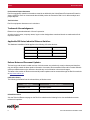
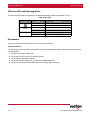
Publication History
The following information lists the release history of this document.
Related Documents
Visit the Technical Resources page on the Red Lion website at the following link to view available documents
related to this product.
Issue/Revision Content Description
Revised 2011-11-29 Document Updates
Revised 2015-11-06 Document reformatted and safety information added.

N-Tron® 300 Series Hardware Guide v
Preface Revised 2015-12-04
www.redlion.net/n-tron_documentation
Document Comments
Red Lion appreciates all comments that will help us to improve our documentation quality. The user can submit
comments through the Red Lion Customer Service. Simply email us at customer[email protected].
Additional Product Information
Additional product information can be obtained by contacting the local sales representative or Red Lion through the
contact numbers and/or e-mail addresses listed on the inside of the front cover.
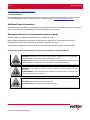
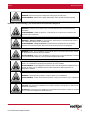
Warnings and Cautions / Avertissements et mises en garde
Warnings apply to situations where personal injury or death may result.
Mises en garde s'appliquent aux situations où des blessures corporelles ou la mort peuvent en résulter.
Cautions apply to where reduced function or damage to equipment may result.
Avertissements s'appliquent à où fonction réduite ou d'endommagement de l'équipement peut entraîner.
General Safety Cautions and Warnings / Précautions et avertissements de sécurité générale
CAUTION: Do not perform any services on the unit unless qualified to do so. Do not substitute
unauthorized parts or make unauthorized modifications to the unit.
ATTENTION: Ne pas effectuer de services sur l'appareil s'il n'est pas qualifié pour le faire. Ne pas
substituer pièces non autorisées ou de modifications non autorisées de l'appareil.
WARNING: Do not operate the unit with the top cover removed, as this could create a shock or
fire hazard.
AVERTISSEMENT - Ne pas faire fonctionner l'unité avec le couvercle retiré, ceci pourrait créer
une décharge électrique ou un incendie.
CAUTION:
Do not block any air vents on the unit.
ATTENTION: N'obstruez pas les fentes d'aération de l'unité.

Preface Revised 2015-12-04
vi N-Tron® 300 Series Hardware Guide
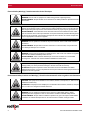
Electrical Safety Warnings / Avertissements de sécurité électrique
Environmental Safety Cautions and Warnings / Sécurité environnementale mises en garde et avertissements
WARNING: Do not work on equipment or cables during periods of lightning activity.
AVERTISSEMENT: Ne pas travailler sur le matériel ou les câbles pendant les périodes d'activité
de la foudre.
WARNING: Properly ground the unit before connecting anything else to the unit. Units not
properly grounded may result in a safety risk and could be hazardous and may void the warranty.
See the grounding technique section of this Hardware Guide for proper ways to ground the unit.
AVERTISSEMENT: Correctement à la terre de l'unité avant tout raccordement à l'unité. Unités
pas correctement mise à la terre peut entraîner un risque de sécurité et pourraient être dangereux
et peut annuler la garantie. Voir la section technique de mise à la terre de ce mode d'emploi des
moyens appropriés à la masse de l'appareil.
WARNING: Do not operate the unit with the top cover removed, as this could create a shock or
fire hazard.
AVERTISSEMENT: Ne pas faire fonctionner l'unité avec le couvercle retiré, ceci pourrait créer
une décharge électrique ou un incendie.
WARNING: Power must be supplied by an isolating source, and a 3.3A max. rated UL recognized
fuse must be installed immediately before the unit.
AVERTISSEMENT: Celui-ci doit être alimenté par une source à isolation et un 3.3A fusible
homologué UL nominale max. doit être installé immédiatement avant l'unité.
CAUTION: Observe proper DC Voltage polarity when installing power input cables. Reversing
voltage polarity can cause permanent damage to the unit and voids the warranty.
ATTENTION: Respecter la polarité correcte de tension DC lors de l'installation des câbles
d'alimentation d'entrée. Inversion de polarité de tension peut causer des dommages permanents à
l'appareil et annule la garantie.
CAUTION: This equipment is suitable for use in Class I, Division 2, Groups A, B, C, and D or non-
hazardous locations only.
ATTENTION: Cet équipement est adapté pour une utilisation dans la classe I, Division 2, Groupes
A, B, C et D ou non dangereux endroits seulement.
WARNING: Do not operate the equipment in the presence of flammable gases or fumes.
Operating electrical equipment in such an environment constitutes a definite safety hazard.
AVERTISSEMENT: Ne pas utiliser le matériel en présence de gaz ou de vapeurs inflammables.
L'utilisation de matériel électrique dans un tel environnement constitue un danger certain.

N-Tron® 300 Series Hardware Guide vii
Preface Revised 2015-12-04
Hazardous Location Warnings / Les avertissements d'emplacement dangereux
WARNING: Disconnect the power cable before removing the enclosure top.
AVERTISSEMENT: Débranchez le câble d'alimentation avant de retirer le boîtier supérieur.
WARNING: Install only in accordance with Local and National Codes of authorities having
jurisdiction.
AVERTISSEMENT: Installer uniquement, conformément aux codes locaux et nationaux des
autorités ayant compétence.
WARNING – Explosion Hazard: Do not connect or disconnect any connections while circuit is
live unless area is known to be non-hazardous.
AVERTISSEMENT - Risque d'explosion: Ne pas brancher ou débrancher les connexions
lorsque le circuit est sous tension sauf si la zone est connue pour être non dangereux.
WARNING: Class I, Div 2 installations require that all devices connected to this product must be
UL approved for the area in which it is installed.
AVERTISSEMENT: Classe I, Div 2 installations nécessitent que tous les périphériques connectés
à ce produit doit être certifié UL pour la zone dans laquelle il est installé.
WARNING: Only UL approved wiring with temperature ratings greater than 90°C permitted for
Class I, Div 2 installations operating at temperatures up to70°C ambient.
AVERTISSEMENT: Seul le câblage homologué UL avec cotes de température supérieure à 90 °C
Permis de classe I, Div 2 installations opérant à des températures allant jusqu'à70°C de
température ambiante.
WARNING: Limited Operating Voltage: 12-30V for Class I, Div 2 installations.
AVERTISSEMENT: Tension de fonctionnement limité: 12-30 V pour la classe I, Div 2 installations.
CAUTION: This equipment is suitable for use in Class I, Division 2, Groups A, B, C, and D or non-
hazardous locations only.
ATTENTION: Cet équipement est adapté pour une utilisation dans la classe I, Division 2, Groupes
A, B, C et D ou non dangereux endroits seulement.

Preface Revised 2015-12-04
viii N-Tron® 300 Series Hardware Guide
Laser Safety Warning / Consignes de sécurité relatives au laser
CAUTION (Only for FXE products): CLASS 1 LASER PRODUCT. Do not stare into the laser.
ATTENTION (Uniquement pour les produits FXE):
PRODUIT LASER CLASSE 1. Ne pas
regarder dans le laser.

N-Tron® 300 Series Hardware Guide 1-1
Introduction and Specifications Revised 2015-12-04
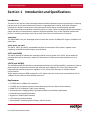
Section 1 Introduction and Specifications
Introduction
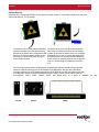
The Red Lion N-Tron® 300 series Unmanaged Industrial Ethernet Switches support high speed layer 2 switching
between ports. All 300 series switches are housed in a ruggedized steel enclosure, and provide Category-5
compliant 10/100-BaseT connections for high performance network design, and hub/repeater upgrades.
The 300 series provides Fast Ethernet connectivity from 4 to 17 ports. These unmanaged switches are available in
copper and fiber port combinations for maximum deployment flexibility.They are also optionally available with
N-View™ monitoring technology, which can be found in the Red Lion monitored family of products.
302MC/MCE
The 302MC/MCE is a 2 port unmanaged media converter that converts 10/100BaseTX copper to 100BaseFX full
duplex fiber.
304TX, 306TX, and 308TX
The 304TX, 306TX, and 308TX are affordable and share a small footprint. Each switch is capable of auto
negotiating 10/100 Mb and half/full duplex communications.
305FX and 306FX2
The 305FX and 306FX2 switches are unmanaged and have 4 ports similar to the 304TX, plus an additional
multimode fiber optic up-link port(s), capable of 2 Kilometers of 100 Mb communications without the use of
repeaters.
305FXE and 306FXE2
The 305FXE and 306FXE2 switches are unmanaged and similar to the 305FX and 306FX2, respectively. However,
these models use singlemode transceivers with extended range capability. The N-Tron FXE products utilize
singlemode fiber transceiver(s) that are capable of 15, 40, and up to 80 Kilometers of 100 Mb full duplex
communications.
All fiber products utilize the IEEE compliant SC or ST duplex connectors for fiber optic communications. All 10/
100Base-TX ports utilize the RJ45 shielded connectors.
Key Features
• Full IEEE 802.3 & 100Base-FX Compliance
• Full IEEE 1613 Compliance (Communications Networking Devices in Electric Power Stations)
• NEMA TS1/TS2 Compliance (Traffic Control Systems)
• American Bureau of Shipping (ABS) Type Approval (Maritime and Offshore Applications)
• Extended Environmental Specifications
• Support for Full/Half Duplex Operation
• LED Link/Activity Status Indication
• Autonegotiation, Autosensing Speed, Duplex, and Flow Control

Introduction and Specifications Revised 2015-12-04
1-2 N-Tron® 300 Series Hardware Guide
• Up to 1.8 Gb/s Maximum Throughput
• Industry Standard 35mm DIN-Rail Mounted Enclosure
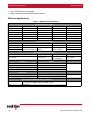
300 Series Specifications
Table 1.
Physical Specifications
Model Height Width Depth Weight
302MC 2.97 in (75.56mm) 2.01 in (50.99mm) 3.17 in (80.56mm) 0.75 lbs (0.3 kg)
304TX 3.06 in (77.64mm) 2.01 in (50.99mm) 3.38 in (85.87mm) 0.75 lbs (0.3 kg)
305FX 3.46 in (87.96mm) 2.01 in (50.99mm) 3.38 in (85.87mm) 0.75 lbs (0.3 kg)
306FX2 3.46 in (87.96mm) 2.01 in (50.99mm) 3.38 in (85.87mm) 0.75 lbs (0.3 kg)
306TX 3.06 in (77.64mm) 2.01 in (50.99mm) 3.39 in (86.08mm) 0.75 lbs (0.3 kg)
308TX 3.46 in (87.96mm) 2.01 in (50.99mm) 3.38 in (85.87mm)
0.75 lbs (0.3 kg)
Electrical Specifications
Input Voltage Input Current Input Ripple Input Wire Size
10-30 VDC (Regulated) 230mA max. @ 24VDC (Steady State) Less than 100 mV 16-28 AWG
Inrush Current 8.0A /0.6 ms @ 24VDC
(302MC/304TX/306TX)
9.0A /0.5 ms @ 24VDC
(308TX)
10A /0.9 ms @ 24VDC
(305FX / 306FX2)
Environmental Specifications
Operating Temperature Storage Temperature Operating Humidity Operating Altitude
-40°C to 70°C -40°C to 85°C
10% to 90%
(non condensing)
0 to 10,000 ft.
Network Media
10BaseT > Cat-3 Cable
100BaseT > Cat-5 Cable
100BaseFX Multimode:50-62.5/125μm Fiber
100BaseFX Singlemode:7-10/125μm Fiber
Connectors
10/100BaseT RJ45 UTP Ports
100BaseFX SC or ST Duplex Port(s) (if equipped)
Recommended Minimum Wiring Clearance
Front
2" (5.08 cm) for 304TX, 306TX, & 308TX models
4” (10.16 cm) for 302MC, 305FX, & 306FX2 models
Side 1" (2.54 cm)
300 Series Key Specifications

N-Tron® 300 Series Hardware Guide 1-3
Introduction and Specifications Revised 2015-12-04
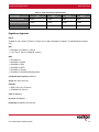
Table 2.
Fiber Length 2km* 15km** 40km** 80km**
TX Power Minimum
-19dBm -15dBm -5dBm -5dBm
RX Sensitivity Maximum
-31dBm -31dBm -34dBm -34dBm
Wavelength
1310nm 1310nm 1310nm 1550nm
[Fiber Transceiver Characteristics
* = Multimode **= Singlemode
Regulatory Approvals
Safety
Suitable for use in Class I, Division 2, Groups A, B, C and D Hazardous Locations, or Nonhazardous Locations
only.
EMI
•
EN61000-6-4, EN55011 - Class A
• FCC Title 47, Part 15, Subpart B - Class A
EMS
•
EN61000-6-2
• EN61000-4-2 (ESD)
• EN61000-4-3 (RS)
• EN61000-4-4 (EFT)
• EN61000-4-5 (Surge)
• EN61000-4-6 (Conducted Disturbances)
Conducted Low Frequency: IEC60533
Shock: IEEE 1613 (250 mm)
Vibration
•
IEEE 1613 (V.S.4 150mm/s)
• IEC60068-2-6 (Test Fc)
Cold: IEC60068-2-1
Dry Heat: IEC60068-2-2
Damp Heat: IEC60068-2-30 (Test Db)

Introduction and Specifications Revised 2015-12-04
1-4 N-Tron® 300 Series Hardware Guide
Certifications
GOST-R Certified

N-Tron® 300 Series Hardware Guide 2-5
Installation Revised 2015-12-04
Section 2 Installation
Introduction
This section contains the information and procedures necessary to unpack, inspect, install and connect the N-Tron
300 series models.
Unpacking
Remove all the equipment from the packaging, and store the packaging in a safe place or dispose according to
your standard operating procedure.
Inspection
Please ensure the shipping package contains the following items in undamaged condition:
1. 300 series unit
2. N-Tron product CD
If the package contents are damaged:
1. Contact your carrier.
2. File any damage claims with the carrier.
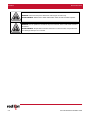
Installing/Mounting
Read the following warning before beginning the installation:
Lire l'avertissement suivant avant de commencer l'installation:
WARNING: Never install or work on electrical equipment or cabling during periods of lightning
activity. Never connect or disconnect power when hazardous gases are present.
AVERTISSEMENT: Ne jamais installer ou de travailler sur un équipement électrique ou de
câblage pendant les périodes d'activité de la foudre. Ne jamais brancher ou débrancher l'alimen-
tation en gaz dangereux sont présents.
CAUTION (Only for FXE products): CLASS 1 LASER PRODUCT. Do not stare into the laser.
ATTENTION (Uniquement pour les produits FXE):
PRODUIT LASER CLASSE 1. Ne pas
regarder dans le laser.

Installation Revised 2015-12-04
2-6 N-Tron® 300 Series Hardware Guide
WARNING: Disconnect the power cable before removing the enclosure top.
AVERTISSEMENT: Débranchez le câble d'alimentation avant de retirer le boîtier supérieur.
WARNING: Do not operate the unit with the top cover removed, as this could create a shock or
fire hazard.
AVERTISSEMENT: Ne pas faire fonctionner l'unité avec le couvercle retiré, ceci pourrait créer
une décharge électrique ou un incendie.

N-Tron® 300 Series Hardware Guide 2-7
Installation Revised 2015-12-04
DIN-Rail Mounting
Install the unit in a standard DIN-Rail. Recess the unit to allow at least 5” of horizontal clearance for fiber optic
cable bend radius (2” for TX models).
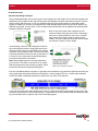
To install the unit to 35mm industrial DIN-Rail,
place the top edge of the included mounting
bracket on the back of the unit against the DIN-
Rail at a 15° angle as shown. Rotate the bot-
tom of the unit to the back (away from you)
until it snaps into place.
To remove the unit from the 35mm industrial DIN-
Rail, place a flat head screwdriver into the orange
release clip found at the bottom of the unit, and apply
downward force on the clip until it disengages from
the bottom of the unit from the DIN-Rail. Rotate the
bottom of the unit towards you and up at an approxi-
mate 15° upward angle to completely remove the
unit.
All N-Tron 300 series products are designed to be mounted on industry standard 35mm DIN-Rail.
However, DIN-Rail mounting may not be suitable for all applications. We offer three alternative
mounting solutions: the 300 Panel Mount Assembly (P/N: 300-PM), the 900 Panel Mount Assembly
(P/N: 900-PM), and the Universal Rack Mount Kit (P/N: URMK). These may be used to securely
mount 302MC, 304TX, 305FX, 306FX2, 306TX, and 308TX units to a panel or standard 19" rack.
300-PM 900-PM URMK

Installation Revised 2015-12-04
2-8 N-Tron® 300 Series Hardware Guide
Connections
Power Connection
1. Unscrew & Remove the DC Voltage Input Plug from the top header.
2. Install the DC Power Cables into the Plug (observing polarity on unit).
3. Plug the Voltage Input Plug back into the top header.
4. Tightening torque for the terminal block power plug is 0.22 Nm/0.162 Pound Foot.
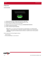
5. All LED’s will flash ON Momentarily.
6. Verify the Power LED stays ON (GREEN).
Note: Either V1 or V2 can be connected to power for minimal operation. For redundant power
operation, V1 and V2 plugs must be connected to separate DC Voltage sources. Use wire sizes of
16-28 gauge. The power cord should be limited to less than 10 meters in order to ensure optimum
performance.
Recommended 24V DC Power Supplies, similar to:
100VAC/240VAC:
N-Tron series NTPS-24-1.3, DC 24V/1.3A

N-Tron® 300 Series Hardware Guide 2-9
Installation Revised 2015-12-04
Ground Connection
300 Series Grounding Techniques
The grounding philosophy of any control system is an integral part of the design. N-Tron 300 series switches are
designed to be grounded, but the user has been given the flexibility to float the switch when required. The best
noise immunity and emissions (i.e. CE) are obtained when the N-Tron switch chassis is connected to earth
ground via a drain wire. Some N-Tron switches have metal DIN-Rail brackets that can ground the switch if the
DIN-Rail is grounded. In some cases, N-Tron switches with metal brackets can be supplied with optional plastic
brackets if isolation is required.
Both V- legs of the power input connector are con-
nected to chassis internally on the PCB. Connecting a
drain wire to earth ground from one of the V- terminal
plugs as shown here will ground the switch and the
chassis. The power leads from the power source should
be limited to 3 meters or less in length.
As an alternate, users can run a drain wire & lug from
any of the DIN-Rail screws or empty PEM nuts on the
enclosure. When using an unused PEM nut to connect
a ground lug via a machine screw, care should be taken
to limit the penetration of the outer skin by less than 1/4
in. Failure to do so may cause irreversible damage to
the internal components of the switch.
Note: Before applying power to the grounded switch,
you must use a volt meter to verify there is no voltage
difference between the power supply’s negative output
terminal and the switch chassis grounding point.
If the use of shielded cables is required, it is generally recommended to only connect the shield at one end to pre-
vent ground loops and interfere with low level signals (i.e. thermocouples, RTD, etc.). Cat5e cables manufac-
tured to EIA-568A or 568B specifications are required for use with N-Tron Switches.
In the event all Cat5e patch cable distances are small (i.e. All Ethernet devices are located the same local cabi-
net and/or referenced to the same earth ground), it is permissible to use fully shielded cables terminated to chas-
sis ground at both ends in systems void of low level analog signals.

Installation Revised 2015-12-04
2-10 N-Tron® 300 Series Hardware Guide
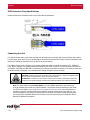
RJ45 Connector Crimp Specifications
Please reference the illustration below for the Cat5 cable specifications:
Connecting the Unit
For 300 series fiber units, remove the dust cap from the fiber optic connectors and connect the fiber optic cables.
For Fiber Optic ports, the TX port on the near station should be connected to the RX port of the far end station, and
the RX port should be connected to the TX port of the far end station.
For 10Base-T ports, plug a Category 3 (or greater) twisted pair cable into the RJ45 connector. For 100Base-T
ports, plug a Category 5 (or greater) twisted pair cable into the RJ45 connector. Connect the other end to the far
end station. Verify that the LNK LED’s are ON once the connection has been completed. To connect any other port
to another Switch or Repeater, use a standard Cat5 straight through or crossover cable.
Note: For units which have the N-View Option, you can validate that all ports are working cor-
rectly by installing the N-View OPC Server software. The software is freely distributed on the Prod-
uct CD and our website (http://www.redlion.net/support/software-firmware). Once the software is
installed, you should view the Ports Counter page to remotely monitor each connected port. You
may find it helpful to copy [Alt]+[Print Screen] the Port Counter information for each port and paste
[Control]+[V] into a Windows document for further review. Please consult your N-View OPC Server
Manual for additional information.
CAUTION: Creating a port to port connection on the same switch (i.e. loop) is an illegal operation
and will create a broadcast storm which will crash the network!
ATTENTION: La création d'un port à l'autre connexion sur le même commutateur (c'est-à-dire
boucle) est une opération illégale et créera une tempête de diffusion qui va planter le réseau!
La page charge ...
La page charge ...
La page charge ...
La page charge ...
-
 1
1
-
 2
2
-
 3
3
-
 4
4
-
 5
5
-
 6
6
-
 7
7
-
 8
8
-
 9
9
-
 10
10
-
 11
11
-
 12
12
-
 13
13
-
 14
14
-
 15
15
-
 16
16
-
 17
17
-
 18
18
-
 19
19
-
 20
20
-
 21
21
-
 22
22
-
 23
23
-
 24
24


dans d''autres langues
- English: N-Tron N-Tron 304TX User manual
Documents connexes
Autres documents
-
red lion 700_7000 Managed Industrial Ethernet Switches Hardware , Vol I & II Manuel utilisateur
-
-
-
red lion RAM-99x1 Series Manuel utilisateur
-
-
Sixnet RAM 9000 Hardware Guide d'installation
-
-
-
-
 ANTAIRA LNX-C800-T Manuel utilisateur
