MULTIPLEX FunJET Ultra Building Instructions
- Catégorie
- Jouets
- Taper
- Building Instructions

www.modellmarkt24.ch
1
F
GB
D
E
I
Bauanleitung 03 ... 07
Building instructions 08 ... 12
Notice de construction 13 ... 18
Instruzioni di montaggio 19 ... 23
Instrucciones de montaje 24 ... 28
Kit Best.-Nr. 21 4245
© Copyright by MULTIPLEX 2010 Version 1.0
Ersatzteile 32
Replacement parts
Pièces de rechanges
Parti di ricambio
Repuestos
www.modellmarkt24.ch

www.modellmarkt24.ch
2
D
F
GB
I
E
Sicherheitshinweise
Prüfen Sie vor jedem Start den festen Sitz des Motors und der Luftschraube - insbesondere nach dem Transport, härteren Landungen
sowieAbstürzen. Prüfen Sie ebenfalls vor jedem Start den festen Sitz und die richtige Position der Tragflächen auf dem Rumpf.
Akku erst anstecken, wenn Ihr Sender eingeschaltet ist und Sie sicher sind, dass das Bedienelement für die Motorsteuerung auf "AUS"
steht.
Im startbereiten Zustand nicht in den Bereich der Luftschraube greifen!
Vorsicht in der Luftschraubendrehebene - auch Zuschauer zur Seite bitten!
Zwischen den Flügen die Motortemperatur durch vorsichtige Fingerprobe prüfen und
vor einem Neustart den Motor ausreichend abkühlen lassen. Die Temperatur ist richtig, wenn Sie den Motor problemlos berühren
können. Insbesondere bei hohen Außentemperaturen kann dieses einige Minuten dauern.
Denken Sie immer daran: Niemals auf Personen und Tiere zufliegen.
Conseils de sécurité
Avant chaque décollage, vérifiez la fixation du moteur et de l'hélice, notamment après le transport, après les atterrissages violents et
après un “Crash”. Vérifiez également, avant chaque décollage la fixation ainsi que le positionnement de l’aile par rapport au fuselage.
Ne branchez l’accu de propulsion que si vous êtes sûr que votre émetteur est allumé et que l’élément de commande moteur est en
position “ARRET”.
Ne mettez pas vos doigts dans l’hélice! Attention à la mise en marche, demandez également aux spectateurs de reculer.
Entre deux vols, vérifiez en posant un doigt dessus, la température du moteur, laissezle refroidir suffisamment avant le prochain
décollage. La température est correcte si vous pouvez maintenir votre doigt ou votre main sur le moteur. Le temps de refroidissement
peut varier jusqu’à 15 minutes s’il fait particulièrement chaud.
Pensez-y toujours: ne volez jamais vers ou au-dessus des personnes ou des animaux.
Safety notes
Before every flight check that the motor and propeller are in place and secure - especially after transporting the model, and after hard
landings and crashes. Check also that the wing is correctly located and firmly secured on the fuselage before each flight.
Don’t plug in the battery until you have switched on the transmitter, and you are sure that the motor control on the transmitter is set to
“OFF”.
When the model is switched on, ready to fly, take care not to touch the propeller. Keep well clear of the propeller disc too, and ask
spectators to stay back.
Allow the motor to cool down after each flight. You can check this by carefully touching the motor case with your finger. The
temperature is correct when you can hold your finger on the case without any problem. On hot days this may take up to 15 minutes.
Please keep in mind at all times: don’t fly towards people or animals.
Note di sicurezza
Prima di ogni decollo controllare che il motore e la eliche siano fissati stabilmente - specialmente dopo il trasporto, atterraggi duri e se il
modello è precipitato. Controllare prima del decollo anche il fissaggio e la posizione corretta delle ali sulla fusoliera.
Collegare la batteria solo quando la radio è inserita ed il comando del motore è sicuramente in posizione ”SPENTO”.
Prima del decollo non avvicinarsi al campo di rotazione della eliche. Attenzione alla eliche in movimento - pregare che eventuali spettatori
si portino alla dovuta distanza di sicurezza!
Tra un volo e l’altro controllare cautamente con le dita la temperatura del motore e farli raffreddare sufficientemente prima di ogni nuovo
decollo. La temperatura è giusta se si possono toccare senza problemi. Specialmente con una temperatura esterna alta questo può
durare fino a 15 minuti.
Fare attenzione: Non volare mai nella direzione di persone ed animali.
Advertencias de seguridad
Compruebe antes de cada despegue que el motor y la hélice estén fuertemente sujetados, sobretodo después de haberlo transportado,
de aterrizajes más fuertes así como después de una caída. Compruebe igualmente antes de cada despegue que las alas estén bien
sujetas y bien colocadas en el fuselaje.
Conectar la batería, cuando la emisora esté encendida y Usted esté seguro que el elemento de mando para el motor esté en ”OFF”.
No meter la mano en la zona inmediata a la hélice cuando el avión esté a punto de despegar. ¡Cuidado con la zona de la hélice! ¡Pedir a
los espectadores que se aparten!
Entre los vuelos hay que comprobar cuidadosamente la temperatura del motor con el dedo y dejar que el motor se enfríe antes de volver
a despegar. La temperatura es correcta, si puede tocar el motor sin problemas. Sobretodo en el caso de temperaturas del ambiente muy
altas, esto puede tardar unos 15 minutos.
Recuerde: No volar nunca hacía personas o animales.
www.modellmarkt24.ch

www.modellmarkt24.ch
3
Machen Sie sich mit dem Bausatz vertraut!
MULTIPLEX – Modellbaukästen unterliegen während der Produktion einer ständigen Materialkontrolle. Wir hoffen, dass Sie mit
dem Baukasteninhalt zufrieden sind. Wir bitten Sie jedoch, alle Teile (nach Stückliste) vor Verwendung zu prüfen, da bearbeitete
Teile vom Umtausch ausgeschlossen sind. Sollte ein Bauteil einmal nicht in Ordnung sein, sind wir nach Überprüfung gern zur
Nachbesserung oder zum Umtausch bereit. Senden Sie das Teil, bitte ausreichend frankiert, an unsere Modellbauabteilung
und fügen Sie unbedingt die vollständig ausgefüllte Reklamationsmeldung (Formular) bei.
Wir arbeiten ständig an der technischen Weiterentwicklung unserer Modelle. Änderungen des Baukasteninhalts in Form, Maß,
Technik, Material und Ausstattung behalten wir uns jederzeit und ohne Ankündigung vor. Bitte haben Sie Verständnis dafür, dass
aus Angaben und Abbildungen dieser Anleitung keine Ansprüche abgeleitet werden können.
Achtung!
Ferngesteuerte Modelle, insbesondere Flugmodelle, sind kein Spielzeug im üblichen Sinne. Ihr Bau und Betrieb erfordert
technisches Verständnis, ein Mindestmaß an handwerklicher Sorgfalt sowie Disziplin und Sicherheitsbewusstsein.
Fehler und Nachlässigkeiten beim Bau und Betrieb können Personen- und Sachschäden zur Folge haben. Da der
Hersteller keinen Einfluss auf ordnungsgemäßen Zusammenbau, Wartung und Betrieb hat, weisen wir ausdrücklich
auf diese Gefahren hin.
Zusätzlich erforderlich:
MULTIPLEX Fernsteuerelemente für das Modell FunJet ULTRA:
Empfohlene Komponenten
2 x Servo Nano Pro MG digi4 Best.-Nr. 6 5117
alternativ Nano Pro KARBONITE® Best.-Nr. 6 5118
Empfänger RX-6-DR light M-LINK Best.-Nr. 5 5809
2 x Verlängerungskabel 30 cm Best.-Nr. 8 5031
Antriebsempfehlung: Antriebssatz FunJet ULTRA Best.-Nr. 33 2647
Inhalt: Motor: Brushless C 3514 – 2900 Best.-Nr. 33 3091
Regler: MULTIcont BL-70 S-BEC Best.-Nr. 7 2287
Propeller: 6“x5,5“ Best.-Nr. 73 3195
Mitnehmer mit Spinner, für Wellen Ø 4 mm, Prop-Bohrung 8 mm Best.-Nr. 33 2329
oder
Antriebsatz FunJet ULTRA Li-BATT powered Best.-Nr. 33 3647
Inhalt wie # 33 2647, jedoch zusätzlich mit Li-BATT FX 3/1-3200 (M6)
Antriebsakku:
MULTIPLEX Antriebsakku Li-BATT FX 3/1-3200 (M6) Best.-Nr. 15 7371
Ladegerät:
MULTIcharger LN-6015 EQU Best.-Nr. 9 2532
Ladestrom 100mA ...6 A
1-15 Zellen NiCd/NiMH -und 1-6 Zellen Lithium Polymer
Klebstoff: Zacki ELAPOR
®
20g VE 20 Best.-Nr. 59 2727
Zacki ELAPOR
®
Super liquid 10g VE20 Best.-Nr. 59 2728
Werkzeuge:
Schere, Kombizange, Klingenmesser, Schraubendreher, Dorn Ø 4-5 mm oder eine kleine Rundfeile
Technische Daten:
Spannweite 783 mm
Rumpflänge 750 mm
Fluggewicht ca. 875 g
Flächeninhalt ca. 14,5 dm²
Flächenbelastung 60 g/dm²
RC-Funktionen Quer-, Höhenruder (Delta Mix erforderlich) und Motorsteuerung
Best.-Nr. 21 4245
www.modellmarkt24.ch

www.modellmarkt24.ch
4
1. Vor dem Bau
Prüfen Sie den Inhalt Ihres Baukastens. Dazu ist die Abb.01+02
und die Stückliste hilfreich.
Montage des Modells:
2. Durchstoßen der Kabelkanäle zum Rumpf
Mit einem Dorn, einer Rundfeile oder Schraubendreher für die
Kabel, Durchbrüche zum Rumpf schaffen. Dazu das Modell
auf den Rücken legen und vom Kabelkanal her den Dorn unter
Drehbewegung einführen. Lose Schaumpartikel entfernen.
Abb. 03
3. Weitere Vorbereitungen
Für beide Ruder die Einkleberuderhörner 24 zum Einbau
vorbereiten.
Abb. 04
Dazu den Gestängeanschluss 25 in das äußerste Loch des
Ruderhorns einsetzen und in Verbindung der U-Scheibe 26
und der Mutter 27 montieren. Achtung: Die Muttern zusätzlich
mit einem Tropfen Lack oder Sekundenkleber sichern.
Sekundenkleber aus Sicherheitsgründen nur mit einer
Stecknadel auftragen.
Den Inbus-Gewindestift 28 vormontieren. In die „Nester“ für
die Ruderhörner Zacki ELAPOR geben, die Ruderhörner
einsetzen und den Kleber aushärten lassen.
Vorsicht: Beim Einsetzen kann Kleber herausspritzen -
Schutzbrille tragen!
4. Die Servos einbauen
Als Servos wurden die MULTIPLEX Nano Pro MG digi4
vorgesehen. Die Servokabel werden mit den Servo-
verlängerungskabel mit Trennfilter # 8 5035 verlängert
(Trennfilter nur bei 35 MHz). Sie benötigen, wenn der
Empfänger vor dem Antriebsakku eingebaut wird, 30 cm
# 8 5031 und wenn der Empfänger hinter dem Akku eingebaut
wird, 15 cm # 8 5019.
Die Servos mit einem Servotester oder mit der Fernsteuerung
auf Neutral stellen. Die Servohebel sollen 90° zum Servo
stehen (ggf. korrigieren). Die Servos mit Klebeband umwickeln
oder einschrumpfen.
Diese Maßnahme soll, beim späteren Einkleben, das Ein-
dringen von Klebstoff in das Servo und insbesondere in das
Servogetriebe verhindern.
In die Servonester sparsam, Zacki ELAPOR geben (und
nur dort, wo das Servo durch Schrumpfschlauch oder Klebe-
band gesichert ist).
Die Servos in die Servonester einsetzen. Das Kabel in den
Servokabelschacht einstecken und die Schächte mit
Klebeband verschließen. Abb. 05
Wichtiger Hinweis
Dieses Modell ist nicht aus Styropor ™! Daher sind Verklebungen mit Weißleim, Polyrurethan oder Epoxy nicht
möglich. Diese Kleber haften nur oberflächlich und platzen im Ernstfall einfach ab. Verwenden Sie nur Cyanacrylat -
Sekundenkleber mittlerer Viskosität, vorzugsweise unser Zacki -ELAPOR® # 59 2727, der für ELAPOR® Partikelschaum
optimierte und angepasste Sekundenkleber. An einigen Stellen wird auch die extrem dünnflüssige Version Zacki
ELAPOR super liquid # 59 2728 benötigt. Bei Verwendung von Zacki-ELAPOR® können Sie auf Kicker oder Aktivator
weitgehend verzichten. Wenn Sie jedoch andere Kleber verwenden, und auf Kicker/Aktivator nicht verzichten können,
sprühen Sie aus gesundheitlichen Gründen nur im Freien.
5.Das Ruder in Betrieb nehmen
Mit einem Klingenmesser nach Abb. 06 den Ruderspalt
seitlich freimachen - er sollte ca. 1mm breit sein. Dann durch
mehrfaches hin und her bewegen das Scharnier gängig
machen. Dabei die Ruder nicht überstrecken und keinesfalls
abtrennen! Arbeitsbereich ca. +/- 45°.
Abb. 06
6. Holm einbauen und die Außenfügel mit dem Mittelteil
verkleben
Den Holm 10 seitlich durch den Rumpf stoßen und mittig
platzieren. Erst später verkleben. Abb.08
7. Außenflügel mit Innenteil verkleben
Außenteile anpassen und mit ZACKi ELAPOR verkleben.
Fertigungsbedingt kann es zu Dickendifferenzen an der
Klebstelle kommen. Durch Druck von Hand (mit den Fingern)
lässt sich der Schaum vor dem Verkleben sauber anpassen.
Das Servokabel verlegen und in Verbindung mit
Verlängerungskabeln in den Rumpf einführen. Die
Kabelkänäle mit klarem Klebeband verschließen. Auch im
Rumpf die Servokabel festlegen, damit sie später beim
Akkuwechsel nicht stören. Abb. 08
8. Holm verkleben
Prüfen Sie sorgfältig, ob der Flügel gerade und ohne
Verwindung ist. Der CFK Holm 10 muss spannungsfrei in
seinem Schacht liegt. Geben Sie am Holm entlang
dickflüssigen ZACKi Elapor an. Den Flügel einige Minuten nicht
belasten.Vor dem Aushärten des Klebers den Flügel auf
Verbiegung prüfen ggf. richten.
9. Rudergestänge
Die Rudergestänge 30 mit Z-Biegung in das innerste Loch
des Servohebels einhängen. Ruderseitig wird das Gestänge
im Gestängeanschluss 25 mittels der Inbusschraube (M3) 28
in Verbindung mit dem Inbusschlüssel 29 befestigt, dabei ist
das Ruder auf Neutral zu stellen. Die Servohutzen 31 links
und 32 rechts anpassen. Entweder mit ZACKi Elapor
einkleben oder mit ein paar kurzen Streifen klarem Klebeband
(z.B. Tesa) ankleben (Servicezugang für das Servo).
Abb. 07+09
10. Gegenhalter für den Haubenverschluss einsetzen
Die Verschlussklammern 22 mit ZACKi Elapor einstreichen
und positioniert einsetzen.
Abb. 10
11. Rumpfrücken schließen
Bevor Sie den Rumpf schließen, kleben Sie die Kabelsicherung
39 in den dafür vorgesehenen Schlitz im Rumpfdeckel.
Den Rumpfdeckel 4 in Verbindung mit der Kabinenhaube 5
anpassen. Die Positionen markieren und den Rumpfdeckel
4 mit dem Rumpf 3 verkleben. Abb. 11.
Die Verschlusszapfen 23 auf der Verzahnung mit Kleber
www.modellmarkt24.ch

www.modellmarkt24.ch
5
bestreichen und in die Kabinenhaube 5 bis zum Ende der
Verzahnung bündig eindrücken.
Die Verschlussklammern 22 positioniert im Rumpf einkleben.
Nachdem der Kleber ausgehärtet ist, die Haube probeweise
einrasten lassen. Abb.12
Achtung:
Den Rumpfdeckel unbedingt mit dem Rumpf sorgfältig
verkleben, nur so erhalten Sie die notwendige strukturelle
Festigkeit.
Abb. 11
12. Motoreinbau und Befestigung
Den Motorspanthalter 11 probehalber auf den Rumpf stecken
Skala nach unten), wenn alles passt, mit Zacki ELAPOR auf
dem Rumpf aufkleben Abb. 13
13. Motoranschluss
Da der Motor im „Druckbetrieb“ arbeitet, muss er im Linkslauf
betrieben werden. Bei Brushless Motoren werden zum
Umpolen zwei der drei Anschlüsse getauscht.
Achtung!
Immer zwischen Regler und Motor umpolen, nicht etwa
zwischen Akku und Regler (schon passiert) - das Ergebnis
ist sonst ein defekten Regler !
14. Antriebseinheit vorbereiten
Der gesamte Antriebsstrang wird von hinten durch den
Motorspanthalter bis nach vorn in den Rumpf eingeführt. Den
Motor mit dem Motorspant 33 bzw. Aluspant aus dem
Antriebssatz verschrauben und den Regler anstecken.
ACHTUNG:
Der beigefügte Motorspant aus Kunststoff ist für Antriebe
bis maximal 330W Eingangsleistung geeignet. Z.B. Für den
Antriebsatz # 33 2630.
Für den ULTRA-Tuningantrieb # 33 2647 und ähnliche Antriebe
ist der Alu Motorspant # 332606 aus dem og. Tuning-
Antriebsset zwingend erforderlich!
Bei der Tuningvariante mit dem Außenläufermotor werden die
Motorkabel bei der Montage in die Kabelsicherung 39
eingehängt. Dazu den Antriebsstrang, um ca. 90° verdreht
nach links, einführen. Den Motor mit dem Spant nach rechts
drehen und darauf achten, dass sich die Motorkabel in der
Kabelhalterung fangen.
Den Motorspant mit dem Motorträger verschrauben. Den
Controller (Regler) an den Empfänger anstecken, benutzen
Sie ggf. eine Verlängerung für das Anschlußkabel.
Abb. 14
Der Propeller arbeitet im FunJet ULTRA auf Schub, daher muss
dieser im Mitnehmer so orientiert sein, dass die Vorderseite
nach vorn in Flugrichtung zeigt. Den Propeller ordnungsgemäß
befestigen und ihn vor jeder Inbetriebnahme
auf Beschädigungen und sicheren Halt überprüfen. Im Zwei-
felsfall den Propeller austauschen. Abb. 15
Nie sich bei laufendem Propeller in der Laufebene aufhal-
ten. Zuschauer auf die Gefahr hinweisen. Sie sind verant-
wortlich!
15. Seitenleitwerk aufkleben
Vorsicht! Vor dem Einkleben der Leitwerke das Dekor auf der
Oberseite der Tragfläche als Ganzes aufbringen. Erst dann
den Bereich für die Leiwerke freischneiden. Nur so gelingt ein
sauberer Beschnitt um die Leitwerke herum. Die
Seitenleitwerke 8+9 „trocken“ einpassen. Falls die
Klebestellen nicht plan auf dem Flügel aufliegen ggf. leicht
nacharbeiten, z.B. durch Grat entfernen. In die
Seitenrudernester auf der Tragfläche ZACKi Elapor angeben
und die Ruder einsetzen. Sofort ausrichten und fixieren bis
der Klebstoff fest ist.
Abb. 16
16. Endmontage
Für den Empfänger wird an der entsprechenden Position im
Rumpf je ein Streifen Klettband (Hakenseite) 20 geklebt. Die
Gegenseite (Velour) wird auf den Empfänger geklebt. Die 35
MHz Empfänger haben wir, aufgrund der Antennenlänge und
dem möglichen Störnebel des Reglers, immer vorn im Rumpf
eingebaut. Bei 2,4 GHz gibt es diese Probleme nicht – hier
bietet sich der Einbau hinter dem Antriebsakku an.
Für den Antriebsakku kleben Sie die Akkuträgerplatte 37 in
den Rumpf, legen aber zuvor den Befestigungsgurt 38
(Klettband Back to Back) ein. Anschließend wird je ein Streifen
Klettband (Hakenseite) auf die Trägerplatte geklebt. Auf den
Antriebsakku kleben Sie oben und unten je ein
Klettbandstreifen (Velour).
Fixierung des Antriebsakkus:
Den Akku zunächt auf der Unterseite an der richtigen Position
fixieren. Eine Seite des Befestigungsgurtes auf der
Akkuoberseite am Velour „einhängen“, den Gurt strammziehen
und endgültig ankletten.
Abb.17
Die endgültige genaue Position des Flugakkus wird beim
Auswiegen festgelegt.
Prüfen Sie vor jedem Start der sicheren
Sitz des Akkus!
Die Empfangsantenne bei 35 Mhz wird durch die durchstoßene
Rumpfwand im Tragflächenkanal verstaut und mit Klebeband
gesichert. Bei 2,4 GHz lassen Sie rechts und links um 90°
versetzt je einen Antennenstummel aus dem Rumpf schauen.
Stecken Sie probehalber alle Verbindungen zusammen.
Den Antriebsakku erst einstecken, wenn Ihr Sender ein-
geschaltet ist und Sie sicher sind, dass das Bedienelement
für die Motorsteuerung auf „AUS“ steht.
Es ist notwendig, dass Ihr Regler eine sogenannte BEC-
Schaltung besitzt (Empfängerstromversorgung aus dem
Flugakku). Nun kurz und vorsichtig den Motor einschalten und
nochmals die Drehrichtung der Propeller kontrollieren (beim
Probelauf Modell festhalten, lose, leichte Gegenstände hinter
dem Modell entfernen).
Vorsicht, auch bei kleinen Motoren und Luftschrauben
besteht erhebliche Verletzungsgefahr!
17. Ruderausschläge und Einstellungen
Um eine ausgewogene Steuerfolgsamkeit zu erzielen, ist die
Größe der Ruderausschläge richtig einzustellen:
Das Höhenruder nach oben (Knüppel gezogen) 10mm
und nach unten (Knüppel gedrückt) 8 mm.
Die Querruderausschläge +/- 8/11 mm
einstellen (negative Differenzierung).
Falls Ihre Fernsteuerung diese Wege nicht zulässt, müssen
www.modellmarkt24.ch

www.modellmarkt24.ch
6
Sie Ihren Gestängeanschluss umsetzen.
Die Neutralstellung für den ersten Start ist ca. 2 mm auf
„hoch“. Wenn Sie sich eingeflogen haben, dürfen die
Ausschläge auch 20% größer sein.
Beim Fliegen wird man in der Regel herunter trimmen müssen.
Nach der ersten Landung markieren Sie diese Ruder-
positionen mit einem wasserfesten Filzschreiber an den
Seitenrudern. Vor jedem Start wird dann ca. 1 mm über diese
Markierung auf „hoch“ getrimmt.
Nach dem Steigflug wieder entsprechend herunter trimmen.
Für die Perfektionisten noch ein Tipp: Das Modell dreht, wie
alle entsprechenden Propellerflugzeuge, leicht gegen das
Drehmoment des Motors um die Längsachse. In unserem
Fall bei Vollgas nach links. Wenn die Fernsteurung es zulässt,
mischen Sie etwas Gas => Quer. Diese Einstellung ist aber
kein "Muß".
18. Motorsturz Voreinstellung
Der Motorsturz ist am Motorträger einstellbar. Für die ersten
Starts ist die Einstellung „0“ zu wählen. Dazu die
Feststellschrauben rechts und links lose einschrauben, den
Motorspant mit dem Daumen niederhalten und mit der
Einstellschraube (unten) auf „0“ stellen. Die Einstellung ist an
der Skala außen, unten am Motorträger abzulesen.
Zum Schluss die Feststellschrauben bis auf den Spant
aufliegend eindrehen und um eine halbe Umdrehung
festziehen.
Achtung:
Keinesfalls die Schrauben kräftiger anziehen, da sich sonst
der Motorspant verbiegt!
19. Auswiegen-Schwerpunkt
Um stabile Flugeigenschaften zu erzielen, muss Ihr FunJet
ULTRA, wie jedes andere Flugzeug auch, an einer bestimmten
Stelle im Gleichgewicht sein. Montieren Sie Ihr Modell flugfertig
und setzen den Antriebsakku ein.
Auf der Unterseite der Tragfläche in der Nähe des
Geometrieknicks, sind halbkugelförmige Markierungen
angebracht.
Hier mit den Fingern unterstützt, soll das Modell waagerecht
auspendeln. Durch Verschieben des Antriebsakkus sind
Korrekturen möglich. Ist die richtige Position gefunden, stellen
Sie durch eine Markierung im Akkukasten sicher, dass der
Akku immer an derselben Stelle positioniert wird. Abb.18
20. Feinabgleich
Die hervorragenden Flugeigenschaften des Modells können
durch einen Feinabgleich von Schwerpunkt und Motorsturz
optimiert werden. Hilfreich ist hier auch der neuartige
Motorträger bei dem der Sturz einstellbar und das
Einstellergebnis auf einer Skala (nur bei Kunststoffspant)
ablesbar ist.
Zunächst fliegen Sie „Vollgas“ trimmen sie das Modell genau
aus. Wenn Sie dann den Motor aus machen, muss sich ein
gleichmäßiger Sinkflug einstellen. Falls das Modell langsam
wird, ist der Sturz zu stark - Sturz zurücknehmen. Falls das
Modell weiter „schießt“, ist der Sturz zu gering - Etwas Sturz
dazu geben und vor dem nächsten Start „hoch“ trimmen. Diesen
Vorgang wiederholen, bis das Modell nach dem Gas
herausnehmen einen sauberen Sinkflug macht und beim
"wieder - Gas - geben" spontan geradeaus ggf. mit etwas
Steigen
voran geht.
Beim Schwerpunktabgleich fliegen Sie mit Vollgas geradeaus,
legen Sie das Modell mit einem Schlag auf den Rücken. Wenn
der Schwerpunkt stimmt müssen Sie etwa 15-20% drücken.
Falls Sie weniger drücken müssen, ist Ihr Schwerpunkt zu
weit hinten - falls mehr, zu weit vorn. In fast allen Fällen ist der
Schwerpunkt durch verschieben des Akkus zu korrigieren.
Wenn es nicht reicht, darf es auch mal etwas Trimmgewicht
sein. Nach der Schwerpunktfeineinstellung müssen Sie die
Motorsturzeinstellung ggf. wiederholen.
21. Noch etwas für die Schönheit
Dazu liegt dem Bausatz ein mehrfarbiger Dekorbogen 2 A+B
bei. Die einzelnen Schriftzüge und Embleme werden
ausgeschnitten und nach unserer Vorlage (Baukastenbild)
oder nach eigenen Vorstellungen aufgebracht.
22. Vorbereitungen für den Erstflug
Für den Erstflug warten Sie einen möglichst windstillen Tag
ab. Besonders günstig sind oft die Abendstunden.
Vor dem ersten Flug unbedingt einen Reichweitentest nach
den Vorgaben Ihres Fernsteuerlieferanten durchführen!
Verbesserung der Empfangsverhältnisse:
1. Trennfilter zwischen Regler und Empfänger
2. Regler/Motorleitungen so kurz wie möglich.
3. Servokabel, auch die vom Regler, nicht parallel zu den
stromführenden Leitungen vom Antrieb legen.
Falls etwas unklar ist, sollte auf keinen Fall ein Start erfolgen.
Geben Sie die gesamte Anlage (mit Akku, Schalterkabel,
Servos) in die Serviceabteilung des Geräteherstellers
zur Überprüfung.
Erstflug ....
Machen Sie keine Startversuche mit stehendem Motor!!!!
Das Modell wird aus der Hand gestartet (immer gegen den
Wind).
Beim Erstflug lassen Sie sich besser von einem geübten
Helfer unterstützen. Das Modell wird mit 1/2 oder mit 3/4
Gas schräg nach oben (20-30°) gestartet!
Nicht wie einen Segler „bergab“!!
Nach Erreichen der Sicherheitshöhe, die Ruder über die
Trimmschieber am Sender so einstellen, dass das Modell
geradeaus fliegt.
Machen Sie sich in ausreichender Höhe vertraut, wie das
Modell reagiert, wenn der Motor ausgeschaltet ist.
23. Sicherheit
Sicherheit ist das oberste Gebot beim Fliegen mit Flug-
modellen.
Eine Haftpflichtversicherung ist obligatorisch. Falls Sie in einen
Verein oder Verband eintreten, können Sie diese Versicherung
dort abschließen. Achten Sie auf ausreichenden Versicherungs-
schutz (Modellflugzeug mit Antrieb).
Halten Sie Modelle und Fernsteuerung immer absolut in
Ordnung. Informieren Sie sich über die Ladetechnik für die
von Ihnen verwendeten Akkus. Benutzen Sie alle sinnvollen
Sicherheitseinrichtungen, die angeboten werden. Informieren
Sie sich in unserem Hauptkatalog - MULTIPLEX -Produkte sind
von erfahrenen Modellfliegern aus der Praxis für die Praxis
gemacht.
Fliegen Sie verantwortungsbewusst! Anderen Leuten dicht
über die Köpfe zu fliegen ist kein Zeichen für wirkliches
Können, der wirkliche Könner hat dies nicht nötig. Weisen Sie
auch andere Piloten in unser aller Interesse auf diese Tatsache
www.modellmarkt24.ch

www.modellmarkt24.ch
7
hin. Fliegen Sie immer so, dass weder Sie noch andere in
Gefahr kommen. Denken Sie immer daran, dass auch die
allerbeste Fernsteuerung jederzeit durch äußere Einflüsse
gestört werden kann. Auch langjährige, unfallfreie Flugpraxis
ist keine Garantie für die nächste Flugminute.
Wir, das MULTIPLEX - Team, wünschen Ihnen beim Bauen
und später beim Fliegen viel Freude und Erfolg.
MULTIPLEX Modellsport
Produktbetreuung und Entwicklung
Klaus Michler
Stückliste FunJet ULTRA
Lfd. Stück Bezeichnung Material Abmessungen
1 1 KIT-Bauanleitung
2A 1 Dekorbogen (Bogen A) bedruckte Klebefolie 350 x 500 mm
2B 1 Dekorbogen (Bogen B) bedruckte Klebefolie 350 x 500 mm
3 1 Rumpf Elapor geschäumt Fertigteil silber
4 1 Rumpfdeckel Elapor geschäumt Fertigteil silber
5 1 Kabinenhaube Elapor geschäumt Fertigteil silber
6 1 Tragfläche links Elapor geschäumt Fertigteil silber
7 1 Tragfläche rechts Elapor geschäumt Fertigteil silber
8 1 Seitenleitwerk links Elapor geschäumt Fertigteil silber
9 1 Seitenleitwerk rechts Elapor geschäumt Fertigteil silber
10 1 Holmrohr CFK-Rohr Ø6 x 4 x 575 mm
11 1 Motorspanthalter FunJet Kunststoff gespritzt Fertigteil
Kleinteile
20 3 Klettband Hakenseite Kunststoff 25 x 60 mm
21 3 Klettband Velours Kunststoff 25 x 60 mm
22 2 Verschlussklammer Kunststoff gespritzt Fertigteil
23 2 Verschlusszapfen Kunststoff gespritzt Fertigteil
24 2 Einkleberuderhorn Kunststoff gespritzt Fertigteil
25 2 Gestängeanschluß Metall Fertigteil Ø6mm
26 2 U-Scheibe Metall M2
27 2 Mutter Metall M2
28 2 Inbus-Gewindestift Metall M3 x 3mm
29 1 Inbusschlüssel Metall SW 1,5
30 2 Querrudergestänge mit Z. Metall Ø1 x 80mm
31 1 Servohutze links Kunststoff tiefgezogen Fertigteil
32 1 Servohutze rechts Kunststoff tiefgezogen Fertigteil
33 1 Motorspant Kunststoff gespritzt Fertigteil
34 2 Schraube für Motorspant Metall M3 x 16mm
36 1 Schraube für Motorspantjust. Metall M3 x 22mm
37 1 Akkuträgerplatte Kunststoff 20 x 60 mm
38 1 Befestigungsgurt für Akku Kunststoff 16 x 200 mm
39 1 Kabelsicherung Kunststoff Fertigteil
www.modellmarkt24.ch

www.modellmarkt24.ch
8
Kit Order No. 21 4245
Examine your kit carefully!
MULTIPLEX model kits are subject to constant quality checks throughout the production process, and we sincerely hope that you
are completely satisfied with the contents of your kit. However, we would ask you to check all the parts before you start
construction, as we cannot exchange components which you have already worked on. If you find any part is not acceptable for
any reason, we will readily correct or exchange it after we have checked it. Just send the component to our Model Department,
with adequate postage pre-paid. Please be sure to fill in the complaint form, duly completed.
We are constantly working on improving our models, and for this reason we must reserve the right to change the kit contents in
terms of shape or dimensions of parts, technology, materials and fittings, without prior notification. Please understand that we
cannot entertain claims against us if the kit contents do not agree in every respect with the instructions and the illustrations.
Caution!
Radio-controlled models, and especially model aircraft, are by no means playthings. Building and operating them
safely requires a certain level of technical competence and manual skill, together with discipline and a responsible
attitude at the flying field. Errors and carelessness in building and flying the model can result in serious personal injury
and damage to property. Since we, as manufacturers, have no control over the construction, maintenance and
operation of our products, we hereby expressly point out these hazards and emphasise your personal responsibility.
Additional items required:
MULTIPLEX radio control system components for the FunJet ULTRA:
Recommended components
2 x Nano Pro MG digi4 servo Order No. 6 5117
alternatively: Nano Pro KARBONITE® Order No. 6 5118
RX-6-DR light M-LINK receiver Order No. 5 5809
2 x 30 cm servo extension lead Order No. 8 5031
Recommended power system: FunJet ULTRA power set Order No. 33 2647
Contents: C3514 - 2900 brushless motor Order No. 33 3091
MULTIcont BL-70 S-BEC speed controller Order No. 7 2287
6” x 5.5” propeller Order No. 73 3195
Propeller driver and spinner, for 4 mm Ø shafts, prop bore 8 mm Order No. 33 2329
or
FunJet ULTRA power set, Li-BATT powered Order No. 33 3647
Contents as # 33 2647, plus LiBATT FX 3/1-3200 (M6) battery
Flight battery
MULTIPLEX LiBATT FX 3/1-3200 (M6) flight battery Order No. 15 7371
Battery charger:
MULTIcharger LN-6015 EQU Order No. 9 2532
Charge current 100 mA ... 6 A
1 - 15 NiCd / NiMH cells and 1 - 6 Lithium-Polymer (LiPo) cells
Adhesive: Zacki ELAPOR® 20 g VE 20 Order No. 59 2727
Zacki ELAPOR® super liquid, 10 g VE 20 Order No. 59 2728
Tools:
Scissors, combination pliers, balsa knife, screwdriver, 4 - 5 mm Ø bradawl or small round file.
Specification:
Wingspan 783 mm
Fuselage length 750 mm
All-up weight approx. 875 g
Wing area approx. 14.5 dm²
Wing loading 60 g/dm²
RC functions Aileron, elevator (delta mixer required) and throttle
www.modellmarkt24.ch

www.modellmarkt24.ch
9
important note
This model is not made of styrofoam™, and it is not possible to glue the material using white glue, polyurethane or
epoxy; these adhesives only produce a superficial bond which gives way when stressed. Use medium-viscosity
cyano-acrylate glue for all joints, preferably our Zacki-ELAPOR®, # 59 2727 - the cyano glue optimised specifically for
ELAPOR® particle foam. At some points the extremely low-viscosity version - Zacki ELAPOR super liquid, # 59 2728,
is required. If you use Zacki-ELAPOR® you will find that you do not need cyano ‘kicker’ or activator for most joints.
However, if you wish to use a different adhesive, and are therefore obliged to use kicker / activator spray, we
recommend that you apply the material in the open air as it can be injurious to health.
1. Before assembling the model
Please check the contents of your kit.
You will find Figs. 01 + 02 and the Parts List helpful here.
Assembling the model:
2. Piercing the cable ducts through the fuselage
Use a bradawl, a round file or a screwdriver to pierce the cable
holes through the fuselage: this is accomplished by placing
the model on its back and twisting the tool into the fuselage,
working from the end of the cable duct. Remove all loose foam
particles.
Fig. 03
3. Remaining preparation work
The next step is to prepare the glue-fitting horns 24 for
installation in the control surfaces. Fig. 04
Fit the pushrod connector 25 in the outermost hole in the horn
and secure it with the washer 26 and nut 27. Check that the
connectors swivel smoothly, but without slop. Caution: secure
the nuts with a tiny drop of paint or cyano to prevent them
working loose, using the point of a pin to apply it.
Fit the socket-head grubscrews 28 in the pushrod connectors.
Apply Zacki ELAPOR to the horn recesses, press the horns
into place, and allow the adhesive to harden.
Caution: drops of glue may be forced out of the joint - wear
protective goggles to be on the safe side!
4. Installing the servos
The model is designed for MULTIPLEX Nano Pro MG digi4
servos. The leads can be extended using servo extension
cables (with integral separation filters), # 8 5035 (filters only
required for 35 MHz). If the receiver is installed forward of the
flight battery you will need 30 cm extension leads, # 8 5031; if
it is aft of the flight pack the extension leads should be 15 cm
long: # 8 5019.
Set the servos to centre from the transmitter, or use a servo
tester. Fit the output arms on the servos at 90° to the case
sides (remove and re-position if necessary). Wrap adhesive
tape round each servo, or shrink a heat-shrink sleeve round
the case.
This measure is intended to prevent adhesive getting inside
the servo when it is glued in place, as it could jam the servo
gearbox.
Apply Zacki ELAPOR sparingly to the servo wells - but only in
the area where the heat-shrink sleeve or adhesive tape round
the servo makes contact.
Place the servos in the wells and press them into place. Run
the cables along the servo ducts and apply adhesive tape over
the slots to prevent them falling out. Fig. 05
5. Freeing the control surfaces
Cut through the tip end of the elevons using a balsa knife,
leaving a gap about 1 mm wide, as shown in Fig. 06. Move the
panels to and fro repeatedly at the pivot axis to free up the
hinges. Take care not to over-stretch the hinge line, and do not
cut off the control surfaces! The working range should be about
+/- 45°.
Fig. 06
6. Installing the wing spar, gluing the outboard wing panels
to the centre section
Slide the tubular CFRP spar 10 through the fuselage from one
side and set it exactly central. Don’t glue it in place at this
stage. Fig. 08
7. Gluing the outboard wing panels to the centre section
Trim the outboard wing panels if necessary to fit against the
centre section, and glue them in place using ZACKi ELAPOR.
Production tolerances may produce slight differences in
thickness at the joint, but hand-pressure is sufficient to
compress the foam to the correct thickness; make any
adjustment required before you glue the joint. Deploy the servo
cables and run the extension leads into the fuselage. Seal the
cable ducts with clear adhesive tape as already described.
Secure the servo leads inside the fuselage so that they do not
get in the way when you have to change the flight battery.
Fig. 08
8. Gluing the spar
Check carefully that the wing is straight and free of warps. The
CFRP spar 10 should be an easy fit in its slot; it must not be
excessively tight. Apply thick ZACKi Elapor along the length of
the spar. Check that the wing remains straight while the
adhesive is still soft, and straighten it if necessary. Allow the
adhesive to cure for a few minutes before placing any load on
the wing.
9. Elevon pushrods
Connect the pre-formed end of the pushrods 30 to the
innermost hole in the servo output arms. At the elevon end slip
the pushrods through the pushrod connectors 25 and tighten
the socket-head M3 grubscrews 28 using the allen key 29;
hold the elevons at neutral while you tighten the screws. Trim
the servo fairings 31 and 32 to fit in the left and right wing
panels respectively. They can be glued in place with ZACKi
Elapor if you wish, but it is generally better to use a few short
strips of clear adhesive tape, as you may need access to the
servo for maintenance.
Fig. 07+09
10. Installing the canopy latch clips
Apply ZACKi Elapor to the canopy latch clips 22, and press
them into position as shown.
Fig. 10
www.modellmarkt24.ch

www.modellmarkt24.ch
10
9. Fitting the fuselage turtle deck
Before installing the fuselage turtle deck, glue the cable retainer
39 in the appropriate slot in the turtle deck.
Trim the fuselage turtle deck 4 to fit, together with the canopy 5.
Mark the position of both parts, then glue part 4 to the fuselage
3. Fig. 11
Press the latch lugs 23 into the latch clips 22 so that they
engage fully. Apply very little cyano to the inside of the slots in
the canopy 5 and immediately fit the canopy on the model,
sliding the latch lugs into the slots. Fig. 12
Wait one minute, then carefully open the canopy and apply
more glue to the latch lugs to reinforce the joints.
Caution:
Be sure to glue the fuselage turtle deck in place securely, as
this joint makes a major contribution to the airframe’s
structural strength.
Fig. 11
12. Installing and securing the motor
Offer up the motor mount 11 to the fuselage (integral scale at
the bottom); and carry out any trimming required. When you
are satisfied with the fit, glue the mount to the fuselage using
Zacki ELAPOR. Fig. 13
13. Connecting the motor
As the motor works in “pusher” mode, it must be connected to
run in the opposite direction to normal; if you are using a
brushless motor simply swap over any two of the three
connections.
Caution!
Always reverse the connections between the speed
controller and the motor, not between the battery and the
controller. It can happen in a moment - and the result is
always a wrecked speed controller!
14. Preparing the motor unit
The whole power train is fitted through the motor mount from
the rear, and threaded forward into the fuselage. Screw the
motor to the motor bulkhead 33 or the aluminium bulkhead
included in the Power Set. Connect the speed controller.
CAUTION:
The plastic motor bulkhead is only suitable for motors with
an input power of up to 330 W, e.g. for the power set, # 33
2630.
If you intend to fit the ULTRA Tuning power set, # 33 2647, or
a similar high-performance motor, it is a fundamental
requirement that you install the aluminium motor bulkhead,
# 33 2606, as supplied in the Tuning power set mentioned
above.
If you are installing the Tuning (upgrade) power system with
outrunner motor, the motor wires should be connected to the
cable retainer 39 when the system is installed. This is
accomplished by initially turning the power train to the left
through about 90°, then turning the motor and bulkhead to the
right, taking care to engage the motor wires in the cable retainer
at the same time.
Screw the motor bulkhead to the motor mount, and connect
the speed controller to the receiver, using a servo extension
lead if required.
Fig. 14
The FunJet ULTRA’s propeller has to push rather than pull, so
it must be positioned in the propeller driver with the front face
pointing forward, in the direction of flight. Secure the propeller
carefully, and check before every session that it is undamaged
and securely fixed. If in doubt, fit a new propeller. Fig. 15
Keep well clear of the spinning propeller, and make sure any
spectators are aware of the danger. You are responsible for
any accident!
15. Installing the fins
Caution: if you opt to use the decal sheet supplied in the kit,
you should apply them to the top surface of the wing now -
before attaching the fins - otherwise there is little chance of
fitting them neatly round the fins. Offer up the fins 8 + 9 “dry” (no
glue) and trim them slightly if necessary. If the joint surfaces
do not make good contact with the wing, remove any rough
edges and sand them back slightly until they do. Apply ZACKi
Elapor to the fin recesses in the wing, and press the fins into
place. Immediately align them accurately and tape them in
position until the glue has set hard.
Fig. 16
16. Final assembly
Stick a strip of Velcro tape (hook side) 20 in the appropriate
position in the fuselage to secure the receiver. Stick the mating
Velcro tape (loop side) 21 to the receiver. In our models we
have always installed the 35 MHz receiver in the fuselage nose,
due to the length of the aerial and the possible interference
generated by the speed controller. With 2.4 GHz equipment
these problems no longer apply, and in this case the receiver
can safely be installed aft of the flight battery.
Glue the battery support plate 37 in the fuselage for the flight
pack, but not before installing the retaining strap 38 (back-to-
back Velcro tape). Stick strips of Velcro tape (hook side) to the
support plate, and apply mating strips of Velcro tape (loop
side) to the top and bottom of the flight pack.
Securing the flight battery:
First place the battery in the correct position and press it onto
the Velcro tape. “Connect” one side of the retaining strap to the
Velcro (loop side) on the top surface of the battery; pull the
strap tight, and finally press the tape surfaces together.
Fig. 17
The final position of the flight battery cannot be established
until you check the balance point of the completed model.
Please ensure that the battery is secure before each and
every flight!
Pierce a hole in the fuselage side leading to the wing duct, and
route the receiver aerial (35 MHz) through it and into the duct,
where it can be secured with adhesive tape. If you are using a
2.4 GHz receiver, allow one of the stub aerials to project out of
the fuselage on each side; the two ends should be angled at
90° to each other .
Temporarily connect all the electrical and electronic
components.
Don’t connect the motor until you have switched the
transmitter on, and are sure that the throttle control is at the
“OFF” position.
Please note that your speed controller must be a BEC type, i.e.
www.modellmarkt24.ch

www.modellmarkt24.ch
11
it must supply power to the receiver from the flight battery. Switch
the motor on briefly, and check the direction of rotation of the
propeller once more. Hold the model very firmly before
switching the motor on, and remove any loose, lightweight
objects from the area behind the model before the propeller
does it for you.
Caution: even small motors and propellers constitute a
serious injury hazard!
17. Control surface travels and settings
The elevon travels must be set correctly in order to obtain a
balanced control response:
Up-elevator (stick back towards you) 10 mm
Down-elevator (stick forward) 8 mm
Aileron travels +8 / -11 mm
(negative differential)
If you cannot set these travels by making adjustments at the
transmitter, you will need to re-position the pushrod connectors
on the elevon horns.
The neutral position
The neutral position for the first flight should be
approximately 2 mm “up”. Once you have test-flown the
model, you may wish to increase the control surface travels
by about 20%.
During test-flying you will normally need to adjust the trims
slightly. After the first landing we suggest that you mark the
correct elevon setting on the fins using a waterproof felt-tip
pen. For the launch phase trim both elevons “up” by about 1
mm, i.e. 1 mm above the marked points.
Remove the up-trim again after the initial climb-out.
One little point to note for the perfectionists amongst you: as is
the case with all aeroplanes featuring this power configuration,
the model has a slight tendency to roll around the longitudinal
axis in reaction to motor torque. The FunJet ULTRA rolls slightly
to the left at full-throttle.
18. Default downthrust setting
The design of the motor mount provides an easy means of
varying the downthrust (inclination of the motor thrustline). For
the first few flights select the “0” setting. This is accomplished
by fitting the right and left locking screws loosely, holding the
motor bulkhead in place with your thumb, and setting the
adjustor screw (bottom) to “0”. The setting should always be
read off on the external scale, at the bottom of the motor mount.
Finally tighten the locking screws carefully until they rest against
the bulkhead, then tighten them by a further half-turn.
Caution: on no account tighten the screws more than this,
as the result will be a deformed motor bulkhead.
19. Balancing - Centre of Gravity
The FunJet ULTRA, like any other aircraft, must be balanced at
a particular point in order to achieve stable flying characteristics.
Assemble your model completely, ready to fly, and install the
flight battery.
You will find hemi-spherical markings in the underside of
the wing close to the change in leading edge angle.
Support the model at this point on two fingertips and it should
balance level; if not, adjust the position of the flight battery to
balance the model as described. Once you have established
the correct position, mark the location of the flight pack insidethe
fuselage to ensure that it is always replaced in the same
position. Fig. 18
20. Fine-tuning
The FunJet ULTRA offers superb flying characteristics which
can be optimised by careful adjustment of the Centre of Gravity
(CG) and motor downthrust. The new design of motor mount
is very helpful here, as it enables you to adjust the downthrust
easily, and the set thrustline can simply be read off on a scale
(plastic bulkhead only).
Start by flying at full-throttle, and trim the model accurately, i.e.
straight and level “hands-off”. If you now switch the motor off,
the aeroplane should make a smooth transition to a steady
glide. If it climbs and slows down, the downthrust is too great
- reduce the downthrust angle. If the model goes into a dive,
the downthrust is insufficient - increase the downthrust slightly
and add a little up-trim before flying again. Repeat this
procedure until the model goes into a smooth descent when
you close the throttle, and responds to an open throttle by
spontaneously flying straight and level, with a slight tendency
to climb.
Fine-tuning the CG: fly straight and level at full-throttle, then
abruptly roll inverted. You will need to apply down-elevator to
maintain level flight, and this should be about 15 - 20% of full
travel. If you need less down-elevator to hold level inverted
flight, the CG is too far rearward; if you need more down-elevator,
it is too far forward. In almost all cases you will be able to
correct the CG by adjusting the position of the flight battery. If
not, add a little ballast to nose or tail as required. If you have to
alter the CG, you will need to re-check the downthrust setting.
21. Gilding the lily - applying the decals
The kit is supplied with two multi-colour decal sheets 2A + 2B.
Cut out the individual name placards and emblems and apply
them to the model in the position shown in the kit box illustration,
or in an alternative arrangement which you find pleasing.
22. Preparing for the first flight
For the first flight wait for a day with as little breeze as possible.
The early evening is often a good time.
Be sure to carry out a range check before the first flight,
using the procedure recommended by your RC system
manufacturer.
Some ideas for improving reception conditions:
1. Install a separation filter between the speed controller and
the receiver.
2. Keep the speed controller / motor cables as short as
possible.
3. Avoid deploying servo leads - including the one attached to
the speed controller - parallel to the high-current motor cables.
If you are not sure about any aspect of the system, please do
not risk a flight. Instead pack up the whole system (including
battery, switch harness and servos) and send it to the
equipment manufacturer for testing.
The first flight ...
Do not attempt to hand-glide this model!
The FunJet is designed for hand-launching only - always launch
directly into wind.
If you are a beginner to model flying we strongly recommend
that you ask an experienced model pilot to help you for the
first few flights. The model should be launched at ½ to ¾-
throttle, with the wings level and the nose angled
up at an
www.modellmarkt24.ch

www.modellmarkt24.ch
12
angle of 20 - 30°.
Don’t launch the model “downhill”, like a glider!
Allow the aeroplane to climb to a safe altitude, then adjust the
trims on the transmitter so that the model flies straight and
level without any assistance from you.
While the FunJet ULTRA is still at a safe altitude, switch off the
motor and try out the controls on the glide.
23. Safety
Safety is the First Commandment when flying any model
aircraft. Third party insurance should be considered a basic
essential. If you join a model club suitable cover will usually be
available through the organisation. It is your personal
responsibility to ensure that your insurance is adequate (i.e.
that its cover includes powered model aircraft).
Make it your job to keep your models and your radio control
system in perfect order at all times. Check the correct charging
procedure for the batteries you are using. Make use of all
sensible safety systems and precautions which are advised
for your system. An excellent source of practical accessories
is the MULTIPLEX main catalogue, as our products are
designed and manufactured exclusively by practising
modellers for other practising modellers.
Always fly with a responsible attitude. You may think that flying
low over other people’s heads is proof of your piloting skill;
others know better: the real expert does not need to prove
himself in such childish ways. Let other pilots know that this is
what you think too. Always fly in such a way that you do not
endanger yourself or others. Bear in mind that even the best
RC system in the world is subject to outside interference. No
matter how many years of accident-free flying you have under
your belt, you have no idea what will happen in the next minute.
All of us in the MULTIPLEX team hope you have many hours
of pleasure building and flying your new model.
MULTIPLEX Modellsport
Product development and maintenance
Klaus Michler
Parts list - FunJet ULTRA
Part No. Description Material Dimensions
No. off
1 1 KIT building instructions
2A 1 Decal set (sheet A) Printed adhesive film 350 x 500 mm
2B 1 Decal set (sheet B) Printed adhesive film 350 x 500 mm
3 1 Fuselage Moulded Elapor foam Ready made, silver
4 1 Fuselage turtle deck Moulded Elapor foam Ready made, silver
5 1 Canopy Moulded Elapor foam Ready made, silver
6 1 L.H. wing panel Moulded Elapor foam Ready made, silver
7 1 R.H. wing panel Moulded Elapor foam Ready made, silver
8 1 L.H. fin Moulded Elapor foam Ready made, silver
9 1 R.H. fin Moulded Elapor foam Ready made, silver
10 1 Tubular spar CFRP tube 6 Ø x 4 Ø x 575 mm
11 1 FunJet motor mount Inj. moulded plastic Ready made
Small items set
20 3 Hook-and-loop tape, hook Plastic 25 x 60 mm
21 3 Hook-and-loop tape, loop Plastic 25 x 60 mm
22 2 Canopy latch Inj. moulded plastic Ready made
23 2 Canopy latch tongue Inj. moulded plastic Ready made
24 2 Glue-fitting horn Inj. moulded plastic Ready made
25 2 Swivel pushrod connector Metal Ready made, 6 mm Ø
26 2 Washer Metal M2
27 2 Nut Metal M2
28 2 Socket-head grubscrew Metal M3 x 3 mm
29 1 Allen key Metal 1.5 mm A/F
30 2 Pre-formed elevon pushrod Metal 1 Ø x 80 mm
31 1 L.H. servo fairing Vac. moulded plastic Ready made
32 1 R.H. servo fairing Vac. moulded plastic Ready made
33 1 Motor bulkhead Inj. moulded plastic Ready made
34 2 Motor bulkhead screw Metal M3 x 16 mm
36 1 Motor bulkhead adjuster screw. Metal M3 x 22 mm
37 1 Battery support plate Plastic 20 x 60 mm
38 1 Battery retaining strap Plastic 16 x 200 mm
39 1 Cable retainer Plastic Ready made
www.modellmarkt24.ch

www.modellmarkt24.ch
13
# 21 4245
Familiarisez-vous avec le kit d’assemblage!
Les kits d’assemblages MULTIPLEX sont soumis pendant la production à des contrôles réguliers du matériel. Nous
espérons que le contenu du kit répond à vos espérances. Nous vous prions de vérifier le contenu (suivant la liste des
pièces) du kit avant l’assemblage, car les pièces utilisées ne sont pas échangées. Dans le cas où une pièce ne
serait pas conforme, nous sommes disposés à la rectifier ou à l’échanger après contrôle. Veuillez retourner la pièce à
notre unité de production sans omettre de joindre le coupon de caisse ainsi que le formulaire de réclamation (document)
dument rempli.
Nous nous réservons le droit de modifications de la forme, dimensions, technologie, matériel et contenu sans préavis. De
ce fait, nous ne prenons donc pas en compte toutes réclamations au sujet des images ou de données ne correspondantes
pas au contenu du manuel.
Attention!
Les modèles radiocommandés, surtout volants, ne sont pas des jouets au sens propre du terme. Leur
assemblage et utilisation demande des connaissances technologiques, un minimum de dextérité manuelle,
de rigueur, de discipline et de respect de la sécurité. Les erreurs et négligences, lors de la construction ou
de l’utilisation, peuvent conduire à des dégâts corporels ou matériels. Du fait que le producteur du kit n’a
plus aucune influence sur l’assemblage, la réparation et l’utilisation correcte, nous déclinons toute
responsabilité concernant ces dangers.
Equipement supplémentaire nécessaire :
Eléments de radiocommande MULTIPLEX pour le modèle FunJet ULTRA :
Equipement conseillé :
2x Servo Nano Pro MG digi4 Nr. Com. 6 5117
alternative Nano Pro KARBONITE® Nr. Com. 6 5118
Récepteur RX-6-DR light M-Link Nr. Com. 5 5809
2x câbles de rallonges 30cm Nr. Com. 8 5031
Propulsion conseillée : Kit de propulsion FunJet ULTRA Nr. Com. 33 2647
Contenu : moteur : Brushless C3514-2900 Nr. Com. 33 3091
Régulateur : MULTIcont BL-70 S-BEC Nr. Com. 7 2287
Hélice : 6’’x5,5’’ Nr. Com. 73 3195
Entraîneur d’hélice avec cône, pour axe Ø 4mm, axe d’hélice 8mm Nr. Com. 33 2329
Ou
Kit de propulsion FunJet ULTRA Li-BATT powered Nr. Com. 33 3647
Contenu type #33 2647, mais avec un accu Li-BATT FX 3/1-3200 (M6)
Kit d’accu de propulsion :
Accu de propulsion MULTIPLEX Li-BATT FX 3/1-3200 (M6 Nr. Com. 15 7371
Chargeur
MULTIcharger LN-6015 EQU Nr. Com. 9 2532
Courant de charge 100mA … 6A
1 – 15 éléments NiCd/NiMh et 1 – 6 éléments Lithium Polymer
Colle : Zacki ELAPOR® 20g VE 20 Nr. Com. 59 2727
Zacki ELAPOR® super liquide 10g VE20 Nr. Com. 59 2728
Outils :
Ciseaux, pince multi, cutter ,tournevis, poinçon Ø 4-5mm ou une petit lime ronde.
www.modellmarkt24.ch

www.modellmarkt24.ch
14
Données techniques :
Envergure 783 mm
Longueur du fuselage 750 mm
Poids en vol env. 875g
Surface alaire env. 14,5 dm²
Charge alaire 60g/dm²
Fonctions RC ailerons, profondeur fonction Delta Mix nécessaire) et moteur.
Information importante
Ce modèle n’est pas en polystyrène™!De ce fait, n’utilisez pas de colle blanche, polyuréthane ou époxy.
Ces colles ne tiennent que superficiellement et cassent sous une contrainte trop importante. N’utilisez
que des colles cyanoacrylate / colle rapide de viscosité moyenne, de préférence notre Zacki-ELAPOR®
# 59 2727 qui est optimisé pour la mousse type ELAPOR® et colle rapide correspondante.
Si vous utilisez notre Zacki-ELAPOR® vous pouvez vous passer d’activateur ou de Kicker. Néanmoins, si
vous utilisez d’autres colles, et que vous ne pouvez pas vous passer d’activateur, veillez utiliser se
dernier dans un endroit bien aéré voir ou de préférence à l’extérieur.
1. Avant de construire
Vérifiez le contenu de la boite avant de débuter les travaux.
Pour cela, vous pouvez vous aider de l’image Fig.1+2 et
de la liste des pièces.
Montage du modèle :
2. Réalisation du passage des câbles du fuselage
A l’aide d’un poinçon, lime ronde ou tournevis effectuez une
ouverture pour le passage des câbles dans le fuselage. Pour
cela, placez le modèle sur le dos et introduisez avec un
mouvement rotatif le poinçon dans le passage de câble à
effectuer. Enlevez les morceaux de mousses inutiles.
Fig. 3
3. D’autres préparations
Préparez les deux guignols à coller 24 pour les ailerons.
Fig. 04
Mettez en place l’élément de fixation de tringle 25 dans le trou
le plus à l’extérieur du guignol et fixez l’ensemble avec la
rondelle 26 et l’écrou 27. Attention: sécurisez la position de
l’écrou en appliquant une goute (aiguille) de colle rapide ou
du frein filet. Utilisez une aiguille pour la mise en place de la
colle.
Pré assemblez l’écrou de serrage 28. Appliquez de la colle
Zacki ELAPOR dans les ‘’évidements’’ de réceptions, placez
les guignols et laissez sécher
Attention : lors de la mise en place des guignols il peut se
produire un éclaboussement – portez des lunettes de
protections !
4. Mise en place des servos
Nous avons prévu l’utilisation des servos MULTIPLEX Nano
Pro MG digi 4. Les câbles de commandes sont utilisés avec
les rallonges équipés de filtres de séparations # 8 5035 (filtre
de séparation uniquement pour le 35MHz). Si vous placez
l’accu de propulsion avant le récepteur il vous faut une rallonge
de 30cm # 8 5031 et si vous placez celui-ci derrière le récepteur
il suffit une rallonge de 15cm # 8 5019.
Mettez les servos en position de neutre avec un testeur de
servos ou votre émetteur. Les palonniers sont placés à 90°
par rapport au servo (corrigez si nécessaire). Emballez les
servos avec du ruban adhésif ou de la gaine thermo rétractable.
Cette dernière opération doit empêcher la colle de rentrer
dans le servo lors de l’opération de collage surtout dans les
engrenages.
Mettez de la colle Zacki ELAPOR dans les ‘’nids’’ (seulement
à ces endroits ou le servo est protégé par le ruban ou la
gaine).
Placez les servos dans les ‘’nids’’. Engagez les câbles dans
les canaux et fixez les avec du ruban adhésif
Fig. 05
5. Libérez les volets
A l’aide d’un cutter, libérez le bord des ailerons comme indiqué
sur la Fig. 06 – la fente doit être d’environ 1mm de large.
Rodez le bord charnière des gouvernes en les faisant bouger
plusieurs fois. Lors de cette action, n’appliquez pas trop de
débattement et surtout ne les séparez pas! Fenêtre de travail
env. +/-45°
Fig. 06
6. Mise en place des longerons et collage des ailes
extérieures avec la partie centrale
Passez le longeron 10 par le côté dans le fuselage et placez-
le au milieu. Celui-ci est collé par la suite.
Fig. 08
7. Collage des bouts d’ailes externes
Adaptez les parties extérieures de l’aile puis collez les avec de
la colle ZACKI ELAPOR. Assurez-vous d’avoir des différences
d’épaisseurs au niveau des zones de collages. Par pression
de votre main (avec les doigts) vous pouvez adapter
proprement la forme des mousses avant le collage. Mettez en
place les câbles de commandes des servos et, une fois
équipés des rallonges, engagez les dans le fuselage. Bouchez
les canaux des câbles proprement avec du ruban adhésif. De
même dans le fuselage afin qu’ils ne gênent pas lorsque
vous allez changer l’accu.
Fig. 08
www.modellmarkt24.ch

www.modellmarkt24.ch
15
8. Collage du longeron
Assurez-vous soigneusement que l’aile soit bien droite et pas
vrillée. Le longeron en fibre de carbone 10 doit se placer
facilement et sans torsions. Placez de la colle ZACKI ELAPOR
le long du longeron. Laissez les ailes sans contraintes pendant
quelques minutes. Avant que la colle ne sèche vérifiez que les
ailes ne se soient pas déformées et si nécessaire rectifiez
leur position.
9. Tringles de commandes
Engagez la partie en forme de Z de la tringle de commande
30. Du côté du palonnier la tringle s’engage dans le système
de fixation 25 puis fixez celle-ci en serrant la vis de blocage
(M3) 28 avec la clé 29, pour cela il faut positionner au neutre
les servos et les gouvernes. Ajustez les habillages de servos
gauche 31 et droite 32. Collez les soit avec de la colle ZACKI
ELAPOR ou avec des bandes de ruban adhésifs double faces
(par ex. : Tesa)
(trappe de visite pour la maintenance du servo)
Fig. 07+09
10. Collage des clips de fermeture de la verrière
Enduisez de colle ZACKI ELAPOR les deux clips de fixations
22 de la verrière puis mettez en position.
Fig. 10
11. Fermeture du dos du fuselage
Avant de fermer le dos du fuselage, collez la sécurité pour les
câbles 39 dans la fente prévue à cet effet sur le couvercle du
fuselage.
Adaptez le couvercle de fuselage 4 avec la verrière 5. Marquez
la position et colle le couvercle de fuselage 4 avec le fuselage
3.
Fig. 11
Clipsez les deux tétons de verrouillage 23 dans les crochets
22. Appliquez très peu de colle dans la fente de la cabine 5
(ZACKI ELAPOR) et mettez directement en place les deux
tétons de verrouillage 23. Fig. 12
Après environ une minute ouvrez délicatement la verrière et
rajoutez de la colle aux tétons.
Attention :
Collez soigneusement le dos du fuselage avec le fuselage,
c’est uniquement de cette manière que vous allez obtenir la
solidité structurelle.
Fig. 11
12. mise en place du moteur et fixation
Effectuez un test de positionnement du support moteur 11 sur
le fuselage (échelle vers le bas) et, si tout se place
correctement, collez celui-ci sur le fuselage avec de la colle
ZACKI ELAPOR.
Fig. 13
13. Branchement du moteur
Du fait que le moteur est monté en ‘’Propulsion’’, celui-ci doit
tourner à gauche. Pour un moteur Brushless il suffit d’inverser
deux des trois câbles d’alimentations.
Attention !
Inversez les câbles entre moteur et régulateur, et non pas
entre l’accu et le régulateur (déjà arrivé) – le résultat est un
régulateur défectueux !
14. Préparation de l’unité de propulsion
Toute l’unité de propulsion est passée de l’arrière du fuselage
à travers le support moteur jusqu’à l’avant du fuselage. Vissez
le moteur sur le support 33 ou en aluminium fourni dans le kit
puis branchez-le sur le régulateur.
Attention :
Le support moteur en plastique fourni ne peu être utilisé
que pour une propulsion ayant au maximum 330W en entrée
comme par exemple le kit de propulsion # 33 2630
Pour notre kit de propulsion Tuning ULTRA # 33 2647 il est
absolument nécessaire d’utiliser le support en aluminium #
33 2606 contenu dans le kit Tuning !
Pour la version Tuning avec le moteur à cloche tournante il
faut placer les câbles d’alimentations dans la sécurité de câble
39. Pour cela il faut tourner le faisceau de câble d’environ 90°
vers la gauche puis mettre en place. Tournez le moteur et le
pare feu vers la droite puis veillez que les câble se placent
dans la partie fixation.
Vissez le pare feu et le support moteur. Branchez le contrôleur
(régulateur) au récepteur, si nécessaire utilisez un câble de
rallonge pour la commande. Pour le test de fonctionnement
Fig. 14
Dans le FunJet ULTRA, l’hélice travaille en propulsion, de se
fait l’entraîneur d’hélice doit être orienté dans le sens de vol.
Fixez l’hélice normalement et, avant de faire un essai, vérifiez
celle-ci si elle est bien fixée et pas défectueuse. Si vous avez
un doute, changez l’hélice.
Fig. 15
Lorsque l’hélice tourne, ne vous placez pas dans le champ
d’action de celle-ci. Prévenir les spectateurs des dangers
potentiels. Vous êtes responsable !
15. Collage des dérives
Attention ! Si vous utilisez la planche de décoration fournie il
faudra appliquée la partie du dos du fuselage avant de coller
les dérives ait que le moteur est monté en ‘’Propulsion’’,
celui-ci doit tourner à gauche. C’est avec cette astuce que
vous réussirez un découpage précis de votre décoration autour
des dérives. Placez les dérives 8+9 sans ‘’collage’’. Rectifiez
si une des surfaces à coller ne repose pas correctement sur
l’aile. Il est parfois nécessaire d’enlever les bavures.
Mettez de la colle ZACKI ELAPOR dans les ‘’nids’’ des dérives
puis mettez les gouvernes en place. Orientez l’ensemble
directement et maintenez jusqu’à ce que la colle soit sèche.
Fig. 16
16. Montage final
Pour le récepteur, collez une bande de velcro 20 (côté crochets)
sur le fuselage à l’endroit désigné. L’autre partie de la bande
velcro (côté velours) se colle sur le récepteur. A cause de la
position de l’antenne et des parasites pouvant émaner du
régulateur nous avons placé le récepteur 35 MHz toujours
devant dans le fuselage. Dans le cas d’une transmission en
2,4GHz cela ne pose aucun problème, la vous pouvez le placer
derrière l’accu de propulsion.
Pour l’accu de propulsion, collez la platine support 37 dans le
fuselage, mais avant, équipez celle-ci de sangles 38 de
fixations pour l’accu (bande velcro Back to Back). Ensuite il
faut coller une bande velcro (partie crochets) sur le support.
Collez au-dessus et en dessous de l’accu des bandes de
velcro (côté velours).
www.modellmarkt24.ch

www.modellmarkt24.ch
16
Fixation de l’accu de propulsion :
Dans un premier temps, placez l’accu dans la bonne position
sur la pièce inférieure. Placez un côté de la sangle de fixation
sur la partie velours sur le dessus de l’accu, tendez de l’autre
côté puis raccrochez la sur le velours.
Fig. 17
La position définitive exacte de l’accu sera déterminée lors du
réglage du centre de gravité.
Vérifiez avant chaque décollage que l’accu soit bien fixé !
L’antenne de réception 35MHz est passée par l’ouverture dans
le fuselage le long du canal dans l’aile et est fixée avec du
ruban adhésif. Pour un système 2,4GHz les bouts d’antennes
sortent à gauche et à droite du fuselage à 90°.
Branchez l’ensemble pour effectuer un essai.
Ne branchez l’accu de propulsion que lorsque l’émetteur
est en marche est qu’il est garantie que l’élément de
commande des gaz est en position ralenti ou ‘’Off’’.
Il est nécessaire que le récepteur possède une fonction BEC
(alimentation du récepteur par l’accu de propulsion). Mettez
en marche délicatement le moteur et vérifiez une dernière fois
le sens de rotation de l’hélice (maintenez fermement votre
modèle, enlevez les pièces libres autour du modèle).
Attention, même avec de petits moteurs et hélices, les
dangers de blessures est élevés !
17. Débattements et réglages
Afin d’obtenir une réaction proportionnelle aux ordres donnés
au travers de vos manches il est important de régler
correctement le débattement des gouvernes :
Profondeur vers le haut (manche tiré) 10 mm
vers le bas (manche poussé) 8 mm
Ailerons à régler sur +/- 8/11mm
(différentiel négatif)
Si votre radiocommande n’arrive pas à atteindre ces valeurs,
il vous faudra changer l’emplacement des tringles de
commandes correspondantes.
La position de neutre
Pour le premier vol il faut placer celle-ci env. 2mm en ‘’haut’’.
Lorsque vous aurez effectué votre premier vol, vous pouvez
augmenter de 20% les débattements.
En règle générale lors du vol il vous faudra trimer vers le bas.
Après le premier atterrissage, marquez la position des
gouvernes à l’aide d’un feutre indélébile sur les ailerons. Après
chaque décollage la position de trim sera environ 1mm ‘’au-
dessus’’ de la marque.
Après le vol pour prendre de l’altitude replacer les trims pour
effectuer un vol horizontal. Un petit truc pour les
perfectionnistes : comme pour tous les modèles motorisés,
celui-ci tourne légèrement dans le sens contraire du couple
moteur autour de son axe longitudinal. Dans notre cas vers la
gauche en plein régime.
18. Préréglage du piqueur moteur
La valeur du piqueur moteur est réglable au travers de son
support. Pour le premier vol il faut choisir la position ‘’0’’. Pour
cela, mettez en place les vis de fixations à droite et à gauche
sans les serrer, maintenir vers le bas le support moteur avec
le pouce et, par action sur la vis de réglage (en-dessous) le
placer sur la marque ‘’0’’. La position de réglage est lisible à
l’extérieur en bas du support moteur.
Pour terminer, vissez complètement la vis de fixation jusqu’à
ce qu’elle touche le pare-feu puis rajoutez un demi tour pour le
serrage.
Attention : ne serrez en aucun cas la vis de fixation trop fort,
sinon celle-ci tord le pare-feu !
19. Equilibrage – centre de gravité
Afin d’obtenir des caractéristiques de vol stables il faut, comme
pour tous les modèles volants, régler l’équilibre à différents
endroits de votre FunJet. Montez complètement votre modèle
et mettez en place l’accu de propulsion.
Sur le dessous de l’aile de votre modèle, dans les environs
du pli géométrique, vous trouverez des marques en demi-
bille.
Placez votre doit à ce niveau et lâchez votre modèle, celui-ci
doit rester à l’horizontal. En modifiant la position de l’accu de
propulsion vous pouvez effectuer des corrections. Lorsque
vous aurez trouvé la bonne position de celui-ci, marquez son
emplacement dans le compartiment afin de toujours pouvoir
le replacer au même endroit.
Fig. 18
20. Réglage fin
Les excellentes caractéristiques de vol de ce modèle peuvent
êtres optimisés par un réglage fin du centre de gravité et du
piqueur moteur. Pour ce dernier, le nouveau système de
support moteur vous simplifie le réglage du piqueur et la
graduation sur celui-ci (sur la partie plastique) vous permet
de lire la valeur.
Dans un premier temps volez en ‘’pleine puissance’’ et trimez
correctement le modèle. Lorsque vous éteignez le moteur,
votre modèle doit se placer en vol descendant régulier. Si celui-
ci ralenti, le piqueur est trop grand, réduire la valeur. Si le
modèle continue ‘’comme une flèche’’, le piqueur est trop faible,
rajoutez en. Effectuez plusieurs fois cet essai jusqu’à ce que
la pente prise par le modèle soit régulière après avoir coupé
les gaz, et, lorsque vous remettez les gaz votre modèle doit
reprendre spontanément le vol droit ou même reprendre un
peu d’altitude.
Pour le réglage du centre de gravité, volez droit en plein régime.
Placez brutalement le modèle sur le dos. Si le centre de gravité
est bien réglé il faut appuyer sur le manche de commande de
la profondeur entre 15 – 20%. Si vous devez appuyer moins, le
centre de gravité est trop loin derrière, et si vous devez pousser
plus, celui-ci est trop en avant. Presque dans tous les cas
vous pouvez corriger la position du centre de gravité en
déplaçant l’accu de propulsion. Si cela ne devait pas suffire, il
est possible de rajouter du poids de trim. Après avoir réglé le
centre de gravité il faut refaire des essais pour vérifier le réglage
du piqueur moteur.
21. Un petit quelque chose pour l’esthétique
Pour cela vous trouverez des décalcomanies couleur 2 A+B
dans le kit. Les différents symboles et écritures sont à
découper et placer comme sur l’exemple (image de la boite)
ou comme bon vous semble.
www.modellmarkt24.ch

www.modellmarkt24.ch
17
22. Préparatifs pour le premier vol
Il est conseillé d’effectuer le premier vol par une météo sans
vent. Pour cela, les occasions se présentent souvent en soirée.
Il est impératif d’effectuer un test de porté avant le premier
vol en fonctions des indications données par le fabricant de
votre radiocommande!
Amélioration des conditions de réceptions :
1. Placez un filtre séparateur entre le régulateur et le récepteur
2. Réduisez la longueur des câbles entre le moteur et le
régulateur aussi court que possible
3. Ne placez pas les câbles de commandes des servos ainsi
que du régulateur parallèlement aux câbles d’alimentations
de la propulsion
Si quelque chose n’est pas clair, n’effectuez surtout pas de
décollage. Envoyez tout l’équipement (avec accu, interrupteur,
servos) au service après-vente de votre revendeur pour
vérification.
Premier vol ...
Ne faite pas d’essais de décollages sans propulsion !!!!
Le modèle est décollé par un lancé à la main (toujours contre
le vent).
Pour votre premier vol, laissez-vous aider par une personne
expérimentée. Mettez les gaz au ½ ou ¾ de la puissance et
lancez-le avec une pente ascendante d’environ (20-30°) !
Pas comme un planeur ‘’vers le bas’’ !!
Après avoir atteint l’altitude de sécurité, réglez les trims des
différentes gouvernes sur votre radiocommande afin que le
modèle vol droit.
Apprenez à connaitre votre modèle à une altitude suffisante,
voyez comment réagit votre modèle lorsque le moteur est éteint.
23. Sécurité
Sécurité est un maître mot dans le monde de l’aéromodélisme.
Une assurance est obligatoire. Dans le cas où vous êtes
membre au sein d’un club, vous pouvez y souscrire une
assurance qui vous couvre suffisamment. Veillez à toujours
être bien assuré (modèles volants avec propulsion).
Entretenez toujours correctement vos modèles et vos
radiocommandes. Informez-vous sur la procédure de
recharge de vos accus. Mettre en œuvre toutes les dispositions
de sécurités nécessaires. Informez-vous sur les nouveautés
que vous trouverez dans notre catalogue général MULTIPLEX.
Les produits ont été testés par de nombreux pilotes
chevronnés et sont constamment améliorés pour eux.
Volez d’une manière responsable afin de ne pas mettre autrui
en danger! Rappelez-vous toujours que même le meilleur
équipement peut toujours être influencé par les paramètres
extérieurs. Une longue carrière de pilote sans incidents n’est
pas une garantie pour les prochaines minutes de vol
Nous, le Team MULTIPLEX, vous souhaitons beaucoup de
plaisir et de succès pendant la construction et le pilotage.
Klaus Michler
www.modellmarkt24.ch

www.modellmarkt24.ch
18
Liste de pièces FunJet ULTRA
Nr. Nbr Désignation Matière Dimensions
1 1 Instructions de montage
2A 1 Planche de décoration Film couleur autocollant 350x500mm
2B 1 Planche de décoration Film couleur autocollant 350x500mm
3 1 Fuselage mousse Elapor pièce complète argent
4 1 Couvercle de fuselage mousse Elapor pièce complète argent
5 1 Verrière mousse Elapor pièce complète argent
6 1 Aile gauche mousse Elapor pièce complète argent
7 1 Aile droite mousse Elapor pièce complète argent
8 1 Dérive gauche mousse Elapor pièce complète argent
9 1 Dérive droite mousse Elapor pièce complète argent
10 1 Longeron Tube fibre de carbone Ø6x4x575mm
11 1 Support moteur FunJet Plastique injecté pièce complète
Petit nécessaire
20 3 Velcro côté crochets Plastique 25x60mm
21 3 Velcro côté velours Plastique 25x60mm
22 2 Clips de fixation verrière Plastique injecté pièce complète
23 2 Tétons de fixation verrière Plastique injecté pièce complète
24 2 Guignols à coller Plastique injecté pièce complète
25 2 Système de fixation de tringle Métal pièce complète Ø6mm
26 2 Rondelle Métal M2
27 2 Ecrou Métal M2
28 2 Vis Imbus de serrage Métal M3x3mm
29 1 Clé Imbus Métal SW 1,5
30 2 Tringle de commande avec embout en Z Métal Ø1x80mm
31 1 Habillage de servo gauche Plastique injecté pièce complète
32 1 Habillage de servo droite Plastique injecté pièce complète
33 1 Pare feu Plastique injecté pièce complète M5
34 2 Vis pour pare feu Métal M3x16mm
36 1 Vis de réglage du pare feu Métal M3x22mm
37 1 Platine support accu Plastique 20x60mm
38 1 Sangle de fixation pour accu Plastique 16x200mm
39 1 Fixation sécurisé de câble Plastique pièce complète
www.modellmarkt24.ch

www.modellmarkt24.ch
19
Acquistate familiarità con il set di installazione!
Le scatole di costruzione per modelli MULTIPLEX sono soggette, in fase di costruzione, a continui controlli relativi alla qualità dei
materiali. Ci auguriamo che siate soddisfatti del contenuto della scatola di costruzione. Vi preghiamo comunque di verificare
tutti i pezzi (in base alla distinta) prima dell’uso, in quanto i componenti già utilizzati per il montaggio sono esclusi dal diritto
di sostituzione. Qualora un componente non sia a posto, siamo disposti a ripararlo o sostituirlo dopo adeguata verifica.
Vogliate inviare il pezzo in oggetto in busta/pacchetto adeguatamente affrancati al nostro reparto di costruzione modelli, non
dimenticando di allegare il modulo di reclamo compilato.
Lavoriamo costantemente all’ulteriore perfezionamento tecnico dei nostri modelli. Ci riserviamo il diritto di effettuare in qualsiasi
momento modifiche al contenuto della scatola di costruzione in termini di forma, misure, tecnica, materiale e attrezzatura senza
preavviso. Vogliate cortesemente comprendere che i dati e le immagini di queste istruzioni non danno diritto a sporgere reclami.
# 21 4245
Attenzione!
I modelli radiocomandati, in particolare gli aeromodelli, non sono giocattoli in senso tradizionale. La loro costruzione
ed il loro azionamento richiedono nozioni tecniche, un minimo di capacità artigianale, disciplina e senso di sicurezza.
Eventuali errori o negligenze durante la costruzione o il funzionamento possono comportare danni a persone e
materiali. Poiché il produttore non esercita influsso sulla costruzione, sulla manutenzione e sull’esercizio, facciamo
esplicito riferimento a questo tipo di pericoli.
Accessori supplementari richiesti:
Elementi radiocomandati MULTIPLEX per il modello FunJet ULTRA:
Componenti consigliati
2 servi Nano Pro MG digi4 Codice ord. 6 5117
in alternativa Nano Pro KARBONITE® Codice ord. 6 5118
Ricevente RX-6-DR light M-LINK Codice ord. 5 5809
2 cavi di prolunga da 30 cm Codice ord. 8 5031
Motore consigliato: set motorizzazione FunJET ULTRA Codice ord. 33 2647
Contenuto: Motore Brushless C3514 – 2900 Codice ord. 33 3091
Regolatore: MULTIcont BL-70 S-BEC Codice ord. 7 2287
Propulsore: 6“x5,5“ Codice ord. 73 3195
Mozzo portaeliche con ogiva, per alberi con Ø 4 mm,
alesatura propulsore da 8 mm Codice ord. 33 2329
ovvero
Set motorizzazione FunJET ULTRA Li-BATT powered Codice ord. 33 3647
Contenuto come # 33 2647, inoltre con Li-BATT FX 3/1-3200 (M6)
Batteria di motorizzazione:
Batteria di motorizzazione
MULTIPLEX Li-BATT FX 3/1-3200 (M6) Codice ord. 15 7371
Caricabatteria:
MULTIcharger LN-6015 EQU Codice ord. 9 2532
Corrente di carico 100mA ...6 A
1-15 celle NiCd/NiMH e 1-6 celle al litio e polimero
Colla: Zacki ELAPOR
®
20g VE 20 Codice ord. 59 2727
Zacki ELAPOR
®
super liquida da 10g VE20 Codice ord. 59 2728
Utensili:
forbici, pinza universale, coltello affilato, cacciavite, mandrino Ø 4-5 mm o una piccola lima tonda
Dati tecnici:
Apertura alare 783 mm
Lunghezza fusoliera 750 mm
Peso aliante ca. 875 g
Superficie alare ca. 14,5 dm²
Carico alare 60 g/dm²
Funzioni RC alettoni, servo elevatore (necessario Delta Mix) e comando motore
www.modellmarkt24.ch

www.modellmarkt24.ch
20
Avvertenza importante
Questo modello non è in polistirolo ™! Pertanto non è possibile incollare con colla bianca, poliuretano o colla epoxy.
Queste colle aderiscono solo superficialmente e non tengono in caso di emergenza. Utilizzate unicamente colla
istantanea in cianoacrilato di viscosità intermedia, preferibilmente la nostra colla istantanea Zacki ELAPOR® # 59
2727, perfezionata e adattata all’espanso sintetico ELAPOR®. In alcuni punti è necessaria la versione estremamente
liquida Zacki ELAPOR super liquid # 59 2728. Se utilizzate i prodotti Zacki-ELAPOR®, potete rinunciare all’uso di kicker
e attivatore. Se invece non potete evitare l’uso di altre colle, spruzzate questi prodotti esclusivamente all’aperto, per
ragioni di salute.
1. Prima del montaggio
Controllare il contenuto della scatola di montaggio. Servitevi
delle figg. 01+02 e della distinta dei pezzi.
Montaggio del modello:
2. Perforazione dei canali per cavi nella fusoliera
Creare dei passaggi per i cavi nella fusoliera servendosi di un
puntale, di una lima circolare o di un cacciavite. Per farlo,
appoggiare il modello sulla parte posteriore ed introdurre il
puntale a partire dal canale del cavo, con movimenti rotatori.
Rimuovere le particelle di espanso sintetico staccatesi dal
modello. Fig. 03
3. Ulteriori preparativi
Preparare le squadrette per i due timoni 24 per il montaggio.
Fig. 04
Inserire il raccordo per rinvii 25 nel foro più esterno della
squadretta per timone e montare con la rondella ad U 26 e
con il dado 27. Attenzione: fissare inoltre i dadi con una goccia
di vernice o di colla istantanea. Per ragioni di sicurezza applicare
la colla istantanea unicamente servendosi di un spillo.
Premontare la chiave a brugola 28. Inserire Zacki ELAPOR
nelle “aperture“ per le squadrette, applicare le squadrette e
lasciare asciugare.
Cautela: durante l’applicazione la colla può schizzare –
indossare occhiali di protezione!
4. Montaggio dei servi
Come servi sono stati previsti i Nano Pro MG digi4 della
MULTIPLEX. I cavi dei servi vengono prolungati con l’apposita
prolunga per servo con filtro antidisturbo # 8 5035 (filtro
antidisturbo solo a 35 MHz). Se la ricevente viene montata
prima della batteria del motore, serve una lunghezza di 30 cm
# 8 5031; se invece la ricevente viene montata dopo la batteria
del motore, serve una lunghezza di 15 cm # 8 5019.
Posizionare i servi in posizione neutrale servendosi di un tester
o del radiocomando. Le squadrette dovrebbero essere ad
angolo di 90° rispetto al servo (eventualmente correggere).
Avvolgere i servi con nastro adesivo o con termorestringente.
Questa misura serve ad evitare che, durante la fase di
incollatura, la colla penetri nel servo ed in particolare negli
ingranaggi.
Inserire con parsimonia la colla Zacki ELAPOR nelle
“aperture” (tuttavia solo nei punti in cui il servo è protetto da
termorestringente o da nastro adesivo).
Inserire i servi nelle “aperture”. Innestare il cavo nella
scanalatura e avvolgere quest’ultima con nastro adesivo.
Fig. 05
5. Messa in funzione del timone
Servendosi di un coltello affilato tagliare lateralmente il bordo
da incernierare come indicato nella Fig. 06 – la larghezza del
bordo dovrebbe essere di ca. 1 mm. Muovere la cerniera
spingendo più volte in avanti e indietro. Evitare di allungare
eccessivamente i timoni e soprattutto di staccarli! Area di
manovra ca. +/- 45°.
Fig. 06
6. Montaggio del longherone ed incollaggio delle ali esterne
alla parte centrale della fusoliera
Inserire il longherone 10 lateralmente nella fusoliera e
collocarlo in posizione centrale. Incollare solo
successivamente. Fig. 08
7. Incollaggio delle ali esterne alla parte interna della fusoliera
Adattare le parti esterne ed incollarle con ZACKi ELAPOR. In
base al lavoro effettuato, si possono verificare differenze di
spessore nel punto di incollaggio. Premendo manualmente
(con le dita) è possibile adattare l’espanso prima di incollare.
Inserire i cavi ed introdurli nella fusoliera insieme ai cavi di
prolunga. Chiudere i canali dei cavi con nastro adesivo chiaro.
Fissare i cavi del servo anche all’interno della fusoliera, affinché
non disturbino successivamente, durante la sostituzione della
batteria. Fig. 08
8. Incollaggio del longherone
Verificare attentamente che l’ala sia diritta e senza torsioni. Il
longherone in fibra di carbonio rinforzata 10 deve trovarsi senza
tensione nella scanalatura. Cospargere lungo il longherone
uno strato spesso di ZACKi Elapor. Evitare di esercitare peso
sull’ala per alcuni minuti. Prima che la colla si asciughi,
verificare la curvatura dell’ala ed eventualmente raddrizzarla.
9. Rinvio
Inserire il rinvio 30 con curvatura a Z nel foro più interno della
squadretta del servo.
Sul lato del timone, il rinvio viene fissato nel raccordo per rinvii
25 tramite la vite a brugola (M3) 28, da avvitare con la chiave a
brugola 29. Il timone deve trovarsi in posizione neutrale.
Adattare i cappucci del servo 31 a sinistra e 32 a destra.
Incollare con ZACKi Elapor o con alcune strisce di nastro
adesivo chiaro (p.es. Tesa) (accesso di servizio per il servo).
Fig. 07+09
10. Inserimento del controsupporto per la chiusura della
capottina
Cospargere le camere di chiusura 22 con ZACKi Elapor ed
applicare nella posizione corretta.
Fig. 10
11. Chiusura del retro della fusoliera
Prima di chiudere la fusoliera, incollare il morsetto per il cavo
39 nell’intaglio previsto nella copertura della fusoliera. Adattare
la copertura della fusoliera 4 in collegamento con la capottina
5. Segnare le posizioni ed incollare la copertura della fusoliera
4 alla fusoliera 3. Fig. 11
www.modellmarkt24.ch
La page est en cours de chargement...
La page est en cours de chargement...
La page est en cours de chargement...
La page est en cours de chargement...
La page est en cours de chargement...
La page est en cours de chargement...
La page est en cours de chargement...
La page est en cours de chargement...
La page est en cours de chargement...
La page est en cours de chargement...
La page est en cours de chargement...
La page est en cours de chargement...
-
 1
1
-
 2
2
-
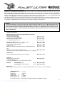 3
3
-
 4
4
-
 5
5
-
 6
6
-
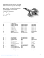 7
7
-
 8
8
-
 9
9
-
 10
10
-
 11
11
-
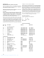 12
12
-
 13
13
-
 14
14
-
 15
15
-
 16
16
-
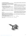 17
17
-
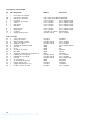 18
18
-
 19
19
-
 20
20
-
 21
21
-
 22
22
-
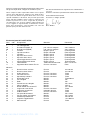 23
23
-
 24
24
-
 25
25
-
 26
26
-
 27
27
-
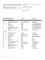 28
28
-
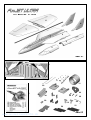 29
29
-
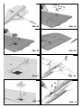 30
30
-
 31
31
-
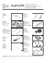 32
32


MULTIPLEX FunJET Ultra Building Instructions
- Catégorie
- Jouets
- Taper
- Building Instructions
dans d''autres langues
- italiano: MULTIPLEX FunJET Ultra
- English: MULTIPLEX FunJET Ultra
- español: MULTIPLEX FunJET Ultra
- Deutsch: MULTIPLEX FunJET Ultra
Documents connexes
-
HiTEC Funjet Ultra 1 Le manuel du propriétaire
-
MULTIPLEX Funjet 2 Ultra Le manuel du propriétaire
-
MULTIPLEX FunJet Le manuel du propriétaire
-
-
HiTEC Kit Mentor Manuel utilisateur
-
-
-
MULTIPLEX Funcub Le manuel du propriétaire
-
-