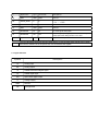
Silex technology SX-USBAC Manuel utilisateur
- Catégorie
- Antennes réseau
- Taper
- Manuel utilisateur

User Manual
SX-USBAC
silex technology, Inc.

1. Notifications
This module is the wireless device using 2.4GHz / 5GHz band. You have to disable 5.15-5.35GHz band (W52, W53)
before use at outdoor in Japan because these band are prohibited to use at outdoor by low restriction.
This module is designed for embedded purpose into the general electric devices, and is not designed for high
reliability demands like aircraft instruments, nuclear control instruments, high reliability medical instruments
(Class III, IV), and high reliability security instruments or any other devices required extremely high reliability and
quality. In the case embedded into the medical instrument, please ask to silex despite the medical class.
As this module communicates by radio wave, it is strongly recommended to use some security system to prevent
unexpected information leakage to others.
This module is a radio module for embedded purpose. Please understand functions and features of this module,
and evaluate as the final product which has this module embedded. Also, as evaluation of EMC conformity of this
module has not been performed, EMC conformity evaluation and application must be performed with the final
product which this module is embedded.
This module will effect to some other device or be affected by the some other device using the same frequency
band. Please investigate the environment to use this module beforehand.
Disassembling or modifying the radio module leads to punishment based on radio law.
This module is the embedded module that has the exposed connectors or some devices. Please be careful for
electro static, condensing, and other dusts.
In the case using the other wireless devices using same frequency band around this product, please take care
below. (See IEEE802.11-2012 and IEEE802.11ac-2013)
1. +/-25MHz (+/-25MHz) or more frequency separation from the center frequency of this module is
recommended in 2.4GHz.
2. Appropriate environment to avoid interference from the adjacent channels or the non-adjacent channels is
necessary.
▢ 2.4GHz: Center frequency +/-25MHz (5Ch), Non Adjacent channel: Further than Center frequency +/-30MHz (6Ch)
▢ 5GHz HT20: Center frequency +/-20MHz (4Ch), Non Adjacent channel: Further than Center frequency +/-40MHz (8Ch)
▢ 5GHz HT40 Adjacent channel: Center frequency +/-40MHz (8Ch), Non Adjacent channel: Further than Center frequency +/-80MHz (16Ch)
▢ 5GHz HT80 Adjacent channel: Center frequency +/-80MHz (16Ch), Non Adjacent channel: Further than Center frequency +/-160MHz (32Ch)
Even if these conditions is satisfied, the module is possibly interfered when strong signal is input.
The other wireless system should be enough far from this module
The input level from the opponent device must be -20dBm or less at 2.4GHz, -30dBm or less at GHz with including
antenna gain.

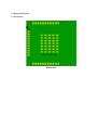
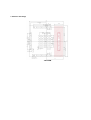
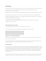
2. Signal pin specifications
2.1. Pin locations
Bottom view

2.2. Signal specifications
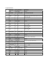
# Signal name Type I/O Domain Descriptions
1 GND GND
GND Ground
2 RESERVED OD VDDIO_GPIO1 Un-used signal. Keep Open.
3 GND GND
GND Ground
4 WOW OD OD
Wake on wireless signal. Low: wake up trigger.
Open drain output. Need external pull-up to IO power rail
of the host system.
5 GND GND
GND Ground
6 RESERVED DI VDDIO_GPIO1 Un-used signal. Keep Open.
7 GND GND
GND Ground
8 GND GND
GND Ground
9 VDD P P Main power supply.
+3.14~+3.46V
10 VDD P P Main power supply.
+3.14~+3.46V
11 VDD P P Main power supply.
+3.14~+3.46V
12 WLAN_PWD_L PD VDDIO_GPIO_1 WLAN reset. (0=Enable, 1=Disable) Internal Pull-down.
13 GND GND
GND Ground
14 GND GND
GND Ground
15 BT_USB_D+ AI,AO
VDD
Bluetooth USB 1.1 differential pair
16 BT_USB_D- AI,AO
VDD
17 GND GND
GND Ground
18 WL_USB_D- AI,AO
VDD
Wireless LAN USB2.0 differential pair
19 WL_USB_D+ AI,AO
VDD
20 GND GND
GND Ground
21 VDDIO_GPIO1 P P IO power supply.
+1.71 ~ +3.46V
22 GND GND
GND Ground
23 BT_PWD_L PD VDDIO_GPIO1 Bluetooth reset. (0=Enable, 1=Disable) Internal Pull-
down.
24 GND GND
GND Ground
25 GND GND
GND Ground
26 NC NA NA NC pin
27 NC NA NA NC pin

# Signal name Type I/O Domain Descriptions
28 GND GND
GND Ground
29 VDDIO_GPIO1 P P IO power supply.
+1.71 ~ +3.46V
30 GND GND
GND Ground
31 GND GND
GND Ground
32 RESERVED DI DI Un-used signal. Keep Open.
33 RESERVED OD OD Un-used signal (Debug port). Connected to a test pad.
Keep Open if the debug function is not used.
EXPGND
Exposed Ground
GND
GND Exposed Ground pads
NOTE1
The Type DI signals which are directed “Keep Open” in case unused, these signals can be Open
because the software in the chip does not concern about these signals.
2.3. Signal definitions
Symbols Descriptions
AI Analog input
AO Analog output
B CMOS bidirectional digital signal
DI CMOS digital input
OD Open drain digital output
P Voltage supply
GND Ground
NA Not applicable

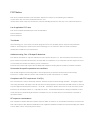
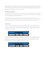
3. Reference land design
TOP VIEW

FCC Notice
This device complies with Part 15 of FCC Rules. Operation is subject to the following two conditions:
(1) this device may not cause harmful interference, and
(2) this device must accept any interference received, including interference that may cause undesired operation.
List of applicable FCC rules
This device complies with below part 15 of the FCC Rules.
Part 15 Subpart C
Part 15 Subpart E
Test Modes
silex technology, Inc. uses various test mode programs for test set up which operate separate from production
firmware. Host integrators should contact silex technology, Inc. for assistance with test modes needed for
module/host compliance test requirements.
Additional testing, Part 15 Subpart B disclaimer
The modular transmitter is only FCC authorized for the specific rule parts (i.e., FCC transmitter rules) listed on the
grant, and the host product manufacturer is responsible for compliance to any other FCC rules that apply to the host
not covered by the modular transmitter grant of certification.
The final host product still requires Part 15 Subpart B compliance testing with the modular transmitter installed.
Summarize the specific operational use conditions
This module designed for mounting inside of the end product by end product manufacturer professionally.
Therefore, it complies with the antenna and transmission system requirements of §15.203.
Compliance with FCC requirement 15.407(c)
Data transmission is always initiated by software, which is the passed down through the MAC, through the digital
and analog baseband, and finally to the RF chip. Several special packets are initiated by the MAC. These are the only
ways the digital baseband portion will turn on the RF transmitter, which it then turns off at the end of the packet.
Therefore, the transmitter will be on only while one of the aforementioned packets is being transmitted. In other
words, this device automatically discontinue transmission in case of either absence of information to transmit or
operational failure.
RF exposure considerations
This equipment complies with FCC radiation exposure limits set forth for an uncontrolled environment and meets the
FCC radio frequency (RF) Exposure Guidelines. This equipment should be installed and operated keeping the radiator
at least 20cm or more away from person’s body.

Co-Location Rule
This transmitter must not be co-located or operated in conjunction with any other antenna or transmitter.
Label and compliance information
Following information must be indicated on the host device of this module.
Contains Transmitter Module FCC ID:N6C-USBAC
Or
Contains FCC ID:N6C-USBAC
FCC CAUTION
The following statements must be described on the user manual of the host device of this module;
FCC CAUTION
Changes or modifications not expressly approved by the party responsible for compliance could
void the users authority to operate the equipment.
Antennas
Recommended Antenna List
Antennas Vendors
Antenna
Type
2.4GHz
Gain
5GHz
Gain
peak Min. peak Min.
SXANTFDB24A55-02
Silex Patern
+2.0dBi
0dBi +3.0dBi
0dBi
H2B1PC1A1C(AA258)
Unictron
PCB +2.9dBi
0dBi +4.4dBi
0dBi
H2B1PD1A1C(AA222)
Unictron
PCB +2.8dBi
0dBi +4.2dBi
0dBi
146153 Molex PCB +3.25dBi
0dBi +5.0dBi
0dBi
WLAN Channel 12 & 13
Product hardware has the capability to operate on channel 12 & 13.
However, these 2 channels will be disabled via software and user will not able to enable these 2 channels.

ISED Notice
This device contains licence-exempt transmitter(s)/receiver(s) that comply with Innovation, Science and Economic
Development Canada’s licence-exempt RSS(s). Operation is subject to the following two conditions:
1. This device may not cause interference.
2. This device must accept any interference, including interference that may cause undesired operation of the device.
L’émetteur/récepteur exempt de licence contenu dans le présent appareil est conforme aux CNR d’Innovation,
Sciences et Développement économique Canada applicables aux appareils radio exempts de licence. L’exploitation
est autorisée aux deux conditions suivantes :
1. L’appareil ne doit pas produire de brouillage;
2. L’appareil doit accepter tout brouillage radioélectrique subi, même si le brouillage est susceptible d’en
compromettre le fonctionnement.
Label and compliance information
The following information must be indicated on the host device of this module.
Les informations suivantes doivent être indiquées sur le périphérique hôte de ce module.
Contains Transmitter Module IC: 4908A-USBAC
Or
Contains IC: 4908A-USBAC
Operation in the band 5150-5350 MHz
Operation in the band 5150-5350 MHz is only for indoor use to reduce the potential for harmful interference to co-
channel mobile satellite systems.
La bande 5150-5350 MHz est réservés uniquement pour une utilisation à l'intérieur afin de réduire les risques de
brouillage préjudiciable aux systèmes de satellites mobiles utilisant les mêmes canaux.
Data transmission
Data transmission is always initiated by software, which is the passed down through the MAC, through the digital
and analog baseband, and finally to the RF chip. Several special packets are initiated by the MAC. These are the only
ways the digital baseband portion will turn on the RF transmitter, which it then turns off at the end of the packet.
Therefore, the transmitter will be on only while one of the aforementioned packets is being transmitted. In other
words, this device automatically discontinue transmission in case of either absence of information to transmit or
operational failure.
La transmission des données est toujours initiée par le logiciel, puis les données sont transmises par l'intermédiaire
du MAC, par la bande de base numérique et analogique et, enfin, à la puce RF. Plusieurs paquets spéciaux sont

initiés par le MAC. Ce sont les seuls moyens pour qu'une partie de la bande de base numérique active l'émetteur RF,
puis désactive celui-ci à la fin du paquet. En conséquence, l'émetteur reste uniquement activé lors de la transmission
d'un des paquets susmentionnés. En d'autres termes, ce dispositif interrompt automatiquement toute transmission
en cas d'absence d'information à transmettre ou de défaillance.
RF exposure considerations
This equipment complies with ISED radiation exposure limits set forth for an uncontrolled environment and meets RSS-
102 of the ISED radio frequency (RF) Exposure rules. This equipment should be installed and operated keeping the
radiator at least 20cm or more away from person’s body.
Cet équipement est conforme aux limites d’exposition aux rayonnements énoncées pour un environnement non
contrôlé et respecte les règles d’exposition aux fréquences radioélectriques (RF) CNR-102 de l’ISDE. Cet équipement
doit être installé et utilisé en gardant une distance de 20 cm ou plus entre le radiateur et le corps humain.
Antenna Type
This radio transmitter (4908A- USBAC) has been approved by Innovation, Science and Economic Development
Canada to operate with the antenna types listed below, with the maximum permissible gain indicated. Antenna types
not included in this list that have a gain greater than the maximum gain indicated for any type listed are strictly
prohibited for use with this device.
Antenna Type Gain Impedance
2.4GHz 5GHz
PCB Antenna 3.25dBi 5dBi 50ohms
Le présent émetteur radio (4908A- USBAC) a été approuvé par Innovation, Sciences et Développement économique
Canada pour fonctionner avec les types d'antenne énumérés ci-dessous et ayant un gain admissible maximal. Les
types d'antenne non inclus dans cette liste, et dont le gain est supérieur au gain maximal indiqué pour tout type
figurant sur la liste, sont strictement interdits pour l'exploitation de l'émetteur.
Type d'antenne Gain Impedance
2.4GHz 5GHz
Antenne PCB 3.25dBi 5dBi 50ohms
-
 1
1
-
 2
2
-
 3
3
-
 4
4
-
 5
5
-
 6
6
-
 7
7
-
 8
8
-
 9
9
-
 10
10


Silex technology SX-USBAC Manuel utilisateur
- Catégorie
- Antennes réseau
- Taper
- Manuel utilisateur
dans d''autres langues
Documents connexes
Autres documents
-
SMK GT3FSCI02 Manuel utilisateur
-
Funai U9W34 Manuel utilisateur
-
LG LGSBWAC93 Manuel utilisateur
-
-
-
Contec FXE3000 Le manuel du propriétaire
-
VESTEL 17WFM26 WiFi Bluetooth Combo Module Manuel utilisateur
-
LG LCWB-001 Wi-Fi BLE + MCU Modul Manuel utilisateur
-
LG PWFSA3 Manuel utilisateur
-
Eurotech ReliaGATE 10-14 Le manuel du propriétaire