
HS300
Operation Manual
Contents subject to change without notice
Version 2.2
2023-03-03

Declarations of compliance
United States
This equipment has been tested and found to comply with the limits for a Class A
digital device, pursuant to Part 15 of the FCC Rules. These limits are designed
to provide reasonable protection against harmful interference when the
equipment is operated in a commercial environment. This equipment
generates, uses, and can radiate radio frequency energy and, if not installed
and used in accordance with the instruction manual, may cause harmful
interference to radio communications. Operation of this equipment in a
residential area is likely to cause harmful interference in which case the user
will be required to correct the interference at his own expense.
Canada
This digital apparatus does not exceed the Class A limits for radio noise
emissions from digital apparatus set out in the Radio Interference
Regulations of the Canadian Department of Communications.
Le présent appareil numérique n’émet pas de bruits radioélectriques
dépassant les limites applicables aux appareils numériques de la Classe A
prescrites dans le Règlement sur le brouillage radioélectrique edicté par le
ministère des Communications du Canada.

Warnings Electrical installation
For your protection, all mains (110V or 230V) equipment used
where damp or wet conditions may occur, must be supplied from a
correctly fused source and protected by an approved ground fault
protection device (RCD, GFCI etc.).
IF IN DOUBT SEEK ADVICE FROM A QUALIFIED
ELECTRICIAN.
To avoid the possibility of electric shock or damage to the machine,
always isolate from the mains power supply before carrying out any
routine maintenance.
Cleaning the scale
Harsh abrasives, solvents, scouring cleaners and alkaline cleaning
solutions, should not be used especially on the display windows.
Under no circumstances should you attempt to wipe the inside of the
machine.
The outside of the machine may be wiped down with a clean cloth
moistened with water containing a small amount of liquid soap.
EMC compliance
The following warning may be applicable to your machine.
WARNING: This is a class A product. In a domestic environment
this product may cause radio interference in which case the user
may be required to take adequate measures.

CONTENT
Ⅰ. SPECIFICATIONS. ……………………………………………… P1
Ⅱ. KEY FUNCTION. ……………………………………………… P3
Ⅲ. CALIBRATION. ………………………………….……………… P6
Ⅳ. Examination mode………………………………………………… P9
Ⅴ. SETUP MODE. …………………………………………………… P10
Ⅵ. Details of RS232 Communication………………………………... P17
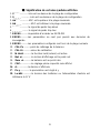
Ⅶ. Calibration resolution, division and capacity …..………………… P20
Ⅷ. Meaning of some displayed symbols. ……………………………. P23
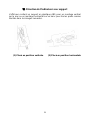
Ⅸ. Direction of indicator with bracket. ………………………. ……… P24
Ⅹ.Key Definition summary: ………………………. ………………… P24
Ⅺ.Parameters setting summary: ………………………………... … P26
Installation Instructions: https://www.brecknellscales.com/resources/videos/


1
140 Indicator Operation Manual
Thank you for purchasing the 140 indicator. Please read all operating
instructions carefully before use and keep the following points in mind:
* Avoid lengthy exposure to extreme heat or cold, your scale works best when
operated at normal room temperature. Always allow the scale to acclimate to a
normal room temperature before use
* Allow sufficient warm up time. Turn the scale on and wait for a few minutes if
possible, to give the internal components a chance to stabilize before weighing.
* These electronic scales are precision instruments. Do not operate near an in-use
cell phone, radio, computer or other electronic device. These devices emit RF and
can cause unstable scale readings. If your scale ever performs poorly, try moving
the scale to a different room or location.
* Avoid using in condition of heavy vibration and airflow.
* Read the weight reading in short time after loading. The output signature of load
cell and A/D may be little influenced after weighing for a long time.
Ⅰ. SPECIFICATIONS:
·SCALE INDICATOR:
1. Input signal range: 0mV ~ +30mV
2. Sensitivity: >0.2uV/grad
3. Internal Resolution: Approximately 520,000 counts
4. Display Resolution: can be selected between 500-100,000
5. System Linearity: within 0.01% of FS
6. Loadcell excitation Voltage: +4.4 VDC (MAX current: 55mA)
Max 4- 350 ohm loadcells.
7. Calibration Method: Software calibration with long-term storage in EEPROM.
·SERIAL COMMUNICATIONS:
1. Mode: Full duplex or only output mode can be selected
2. Baud rate: 1200, 2400, 4800, 9600, or 19200 bps
3. Data format: 8N1, 7E1, 7O1
8data bits, non parity, 1 stop bit
7data bits, 1bit even or odd parity, 1 stop bit
4. Protocol: 7selected protocol (include the one compatible with NCI standard
SCP-01)
5. Output data: gross weight, net weight, tare weight, indicator displaying weight,
weighing unit etc.

2
·OPERATION INTERFACE:
1. Display: 0.65” (17mm) 7-segment LCD, 51/2 digits
2. Keyboard: 4-key push button
·POWER:
1. Alkaline Batteries: 4 x “AAA” size cells
When all displayed segments of LCD flashed, this indicates the batteries are
low below 4.9V and you’d better to replace batteries;
When “Lo.bAt” displayed, this indicates the batteries are low below 4.7V and
you should replace batteries immediately.
2. AC Adapter: 6VDC, 500mA, with central negative:
3. Work current: ≤25mA
(when voltage in 5Vdc-8Vdc and not include load cell’s consumption)
·OPERATION TEMPERATURE: 20℃±15℃
STORE TEMPERATURE: -10℃-70℃
OPERATION HUMIDITY: ≤95%RH (no condensate)
·LOADCELL:
Because of more than one load cell can be used on a scale, following are
required on the load cell set to be used with this indicator,
1. Sensitivity: 0.3mV/V --- 3mV/V (must be fit to >0.2uV/display grad)
2. Input Resistor: ≥80 Ω
3. Output Resistor: <10 KΩ
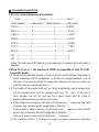
·LOADCELL WIRING:
PIN 1: RED, EXCITATION +
PIN2: BLACK, EXCITATION –
PIN3: GREEN, SIGNAL -
PIN4: WHITE, SIGNAL +

3
Ⅱ. KEY FUNCTION:
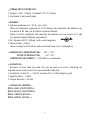
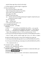
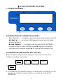
1. FACEPLATE:
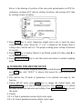
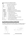
2. DISPLAY SYMBOL MEANING:
Zero ◄--------The scale is at zero point and the gross weight is 0
Net ◄---------The display reading is net weight, and the tare weight is not 0.
Hold -------The scale is under HOLD mode.
It displays the current live weight when flashed, and the locked reading will
be shown when does not flash and comes steady.
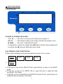
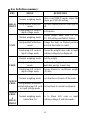
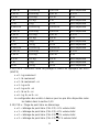
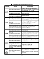
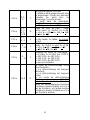
3. SUMMARY of KEY DEFINITION:
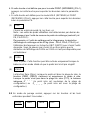
3.1 In normal weighing mode press and hold down keys for 3 seconds:
(1)
a. If this key is only set for HOLD (P2=0), press this key to enter or exit HOLD
mode.
b. If this key is only set for PRINT (P2=1), press this key to output the data
according to P4 setting.
c. If this key is set for both HOLD and PRINT function (P2=2), press this key to
output the data according to P4 setting.
HOLD
PRINT
UNIT
TARE
ZERO
HOLD
PRINT

4
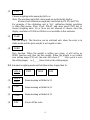
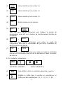
(2)
Choose weighing units among kg-lb-lb: oz
Note: The weighing units that can be used are restricted by display
division, and calibration weight unit (restricted by P8, P9, and P10):
For example, if the calibration unit is “kg”; calibration display resolution
is 50kg (that means: P8=5, P9=0, P10=0), and users press UNIT key to
choose weighing units. Lb or lb:oz are not allowed to choose, since the
display resolution of 100lb or 2000oz is not available to this indicator.
(3)
Tare the weight. This function can be activated only when the scale is in
stable mode and the gross weight is not negative value.
(4)
Zero function. When the weight is within zero range, it will active as
ZERO function and clear the tare weight. When the weight is not within
zero setting range (P13 set), the scale will show 0ˉ ˉ ˉ ˉ (zero point is over
the setting range), or 0_ _ _ _ (zero is below the setting range).
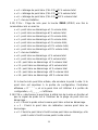
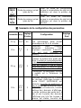
3.2. In normal weighing mode and hold down time longer than 3s:
(1) Same meaning with that in 3.1
(2) Same meaning with that in 3.1
(3) Same meaning with that in 3.1
(4) Power off the scale.
UNIT
TARE
ZERO
HOLD
PRINT
UNIT
TARE
OFF
HOLD
PRINT
UNIT
TARE
OFF

5
(5) +
Hold these two buttons to show firmware version; A/D code or input
working voltage of indicator.
(6) +
Hold these two buttons to enter setting mode when the sealed calibration
switch is on.
(7) +
Hold these two buttons to enter calibration mode when the sealed
calibration switch is on.
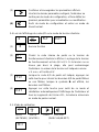
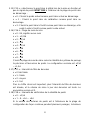
3.3 In setting mode:
HOLD UNITS TARE OFF/ON
(1) Rotate the flashed position from right to left
(2) Change the digit on flashed position. The digit can be changed
to 0, 1, 2…9; and be flashed.
(3) Confirm receiving and storing the displayed parameters,
After the setting of the last parameter, the indicator will
not exit the setup mode, and cycles from the first parameters
for viewing or modifications.
(4) Exit from setting mode to normal work mode
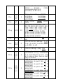
3.4 In displaying A/D code or input voltage mode:
(1) No function
OFF
HOLD
PRINT
OFF
UNIT
OFF
TARE
X
WT
VOL
FLT
EXT
X

6
(2) Choose the weight inner code or input working voltage to be
displayed. The working voltage range is 4.8V-8V. If the voltage
is not within range, it may damage the indicator. Voltage value
is shown like this “U x.xx” and its unit is V.
(3) When A/D code of weight is shown, press this button to choose
filtered or un-filtered weight A/D data; when is on, the data
is filtered.
(4) Press this button to exit this mode, and auto-reset the indicator,
display all segments of LCD, full capacity… just like power on
again and then it goes back to normal weighing mode.
3.5 Calibration mode
HOLD UNITS TARE OFF/ON
(1) Rotate the flashed position from right to left
(2) Change the digit on flashed position. The digit can be changed
to 0, 1, 2…9; and be flashed.
(3) Confirm receiving input data and go into next step.
(4) Exit from calibration mode to normal work mode
Ⅲ. CALIBRATION:
Before calibrate the scale, you should prepare a standard weight (more than
10% of FS weight, and the unit is same as P10 setting) for calibration.
1. Move away any weight on scale. When normal weighing mode, press and
hold down TARE and ON/OFF/ZERO buttons to enter calibration mode.
2. When the indicator shows” CAL-?”, the scale is ready for calibration. Press
WT
VOL
FLT
EXT

7
TARE to confirm and go to next step, or press ON/OFF/ZERO to exit the
calibration mode.
3. The 140 indicator will display “CAP.--”, that means the following data is the
full capacity according to your setting of display resolution (P7), display
division value (P8) , location of decimal point-dot in calibration unit (P9) and
capacity’s unit in calibration (P10). If the setting of FS is more than 199999
(regardless of decimal point and weight unit), the FS capacity will be shown
by first four digits and last four digits: “Hxxx” and “Lxxx”.
For example, the display resolution is selected to 100000(P7=31), the display
division is selected to 5(P8=2), the position of decimal point is selected to
one point after zero (P9=1). The calibration unit is chosen as lb (P10=1), so
the full capacity 50000.0lb will be shown as H 50 and L000.0 in lb unit. Also,
in other modes, the data will be shown as “Hxxx” and “Lxxx” when current
display data is larger than 199999 kg/lb (not include decimal point).
Press TARE to go to next step directly; press ON/OFF/ZERO to exit the
calibration mode; or after a few seconds, it will automatically to next step.
4. The scale will automatically display the setting of division. Firstly it will
display “d.--”, and then the data according to your setting of P8, P9 and P10.
You may choose division among these as below:
Table1:
0.0001kg/lb
0.0002kg/lb
0.0005kg/lb
0.001kg/lb
0.002kg/lb
0.005 kg/lb
0.01kg/lb
0.02 kg/lb
0.05 kg/lb
0.1kg/lb
0.2 kg/lb
0.5 kg/lb
1kg/lb
2 kg/lb
5 kg/lb
10kg/lb
20 kg/lb
50 kg/lb
Press TARE to go to next step directly; press ON/OFF/ZERO to exit the
calibration mode; or after a few seconds, it will automatically to next step.
5. When ‘CAL.P0’ is displayed, that means the scale will begin to calibrate
scale’s zero-point. Move away any weight on the scale. Press TARE button
to confirm, or press ON/OFF/ZERO to exit this mode.
6. When ‘CAL.P1’ is displayed, the scale will be calibrated on second
calibration point. The default standard weight is 50%FS, and at the same, you

8
can press ON/OFF/ZERO to exit the calibration mode. Or load 5%-100%FS
weight, and use PRINT/HOLD and UNIT keys to input the loaded weight.
If the input data is larger than 199999, it will show as “Hxxx” and “Lxxx”. If
the triangular symbol on the left bottom of LCD window appears, it means
that the digit being changed is the displayed most significant bit which can
only be 0/blank or 1. Press TARE key to confirm your setting and the
indicator will flash the input standard weight. Wait till the scale comes steady,
and input A/D data as per the standard weight.
The indicator will automatically go to next step, if the second point can be
calibrated correctly. If there’s an error occurred, the scale will display “CAL.
Er” and return back to step 5 for re-calibration.
7. When ‘CAL.P2’ is displayed, the scale will be calibrated on third calibration
point. When xxxxxx kg (or lb) is displayed (100% FS is default), you can
press ON/OFF/ZERO to exit the calibration mode or Place a standard
weight (must be in the range of 10%-100% FS, and equal or larger than that
for the second calibration point; this is also the range of your input number)
on the scale. Use PRINT/HOLD and UNIT key to input the standard
weight’s value. Use TARE key to confirm the standard weight and input
number are correct. If the calibration weight for third point is same with that
for second point and the calibration weight is more than 10%FS, input the
standard calibration weight same as second point calibration and press TARE
key to confirm the setting. The indicator will flash the input weight. If the
indicator get reasonable data (the input weight is correct, and the calibration
weight of third calibration is more than equal to the calibration weight of
second calibration), it will go to next step automatically. If there’s an error
occurred, the scale will display “CAL.Er” and return back to step 5 for
re-calibration.
8. When ‘CAL.P0’ is shown again, that means the scale will calibrate scale’s
zero-point again. Now, you can press ON/OFF/ZERO to exit the calibration
mode; or Move away any weight on the scale, press TARE key to confirm;
the displayed data will blink. If the indicator gets reasonable data, it will
calculate and store all parameters in EEPROM. And then it will auto-reset
and display all segments of LCD, full capacity… like power on again. If
there’s an error occurred in calibration, the scale will display “CAL.Er” and

9
try to repeat from step 5. The scale will return to normal weighing mode.
Attention: To ensure the accuracy of the scale, it is recommended to use over
75% full capacity weight to calibrate.
Ⅳ. DISPLAY ADC CODE OR INPUT WORKING VOLTAGE VALUE
1. In normal weighing mode, press and hold down ON/OFF/ZERO and
HOLD/PRINT key more than 3s, until ‘codE’ is shown, this means you have
been in display inner code mode; but first, the indicator will show the firmware
version “xx.xx.xx”. In this mode, you can examine the inner working voltage,
the stability of weighing system, the variety value of A/D data as per the loaded
weight.
NOTE:
1) The increment of A/D code for FS weight must be larger or equal to 2 times
of selected display division-n; otherwise, the calibration cannot be properly
completed. Eg. The display division is 0.1kg. Load 100kg standard weight
on the platform, the increment of A/D code is at least 2x 100kg/0.1kg=
2x1000=2000. In this case, the scale can be calibrated. Otherwise, smaller
division needs to be chosen.
2) The data should be stable; otherwise, the calibration cannot properly
complete.
2. In this mode, you can calculate the proper ADC data at zero point by examining
the A/D data for loaded weight. If the ADC increase for full capacity is NFS,
the power-on zero range is set to Zp% FS (P12 setting) and zero key range is
set to Zk% FS (P13 setting). Then proper ADC data of zero point is larger than
(Zp%+ Zk%) x NFS.
ADC increase for full capacity (NFS) can be making out by: Load the weight
W on the platform, and the ADC increase for W weight is Nw. The ADC
increase for full capacity WFS is (NFS)= (Nw)x (WFS)/W .
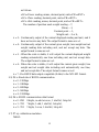
Negative value may be displayed because of error connect of loadcell or error
position of the zero-point potentiometer on PCB; however, the software only
deals with positive value. So, if the position of zero-point potentiometer is
error, adjust potentiometer’s position to make the ADC data will be positive
value and larger than (Zp%+ Zk%) x NFS. Normally the indicator is
factory-calibrated, and end users do not need this operation.

10
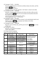
Below is the drawing of position of the zero-point potentiometer on PCB for
conference, decrease ADC data by rotating clockwise, and increase ADC data
by rotating counter-clockwise.
3. Press UNIT key to select displaying weight inner code or input the inner
working voltage value. When the “U x.xx” is displayed, the display digit is
voltage value, and the unit is V. The proper working power voltage is between
5V and 8V.
4. Press TARE key to display filtered or un-filtered weight A/D data; when is
on, the data is filtered.
5. Press ON/OFF/ZERO key to exit this mode and return to normal weighing
mode.
Ⅴ. WORKING PARAMETER SETUP:
1. When scale is in normal weighing mode, press and hold down ON/OFF/ZERO
and UNIT key until “SEtUP” is shown, that means the scale is in SETUP
mode.
2. This indictor has 19 kinds of parameters to be selected and setup by this
function.
3. During SETUP mode, press UNIT key to change the flashed digits, and
HOLD/PRINT key to shift the flashed position. Press TARE key to confirm
and save the set data and enter next setting. Press ON/OFF/ZERO key to exit
this mode.
4. Display
1) P A.B: Item A parameters and one digit can be input.
2) P A.BC: Item A parameters and two digits can be input

11
3) PAB.C: Item AB parameters and one digit can be input
4) PAB.CD: Item AB parameters and two digits can be input
5. Detailed setup:
5.1) P1.xy: Auto-off time xy= 00-15
xy = 00 : means no auto-off function
xy = 01-15: means the scale turns off to save power after 01-15 minutes when
no variety of weight on scale and no key operation.
5.2) P2.x: HOLD/PRINT key function definition
x = 0 : only HOLD function
x = 1 : only PRINT function
x = 2 : HOLD and PRINT function (short-time click the button once for Print
function, and hold the button for several seconds for HOLD function)
5.3) P3.xy: Hold function setting
xy = 0 : No hold function;
xy = 1 : When the scale becomes stable, it will hold the larger weight reading;
xy = 2 : When the scale becomes stable, it will automatically display and hold
the weight reading. When this weight is below 10d, HOLD function
will automatically inactivated. When the new weight is more than
10d, the scale will hold the new weight when stable.
xy=3-50 : When the weight variety is within the setting range +3~50d, the
weight reading will remain unchangeable.
5.4) P4.x: RS232 mode setting
x = 0 : No RS232 function. It will not transmit or receive any data although
the scale is with RS232 hardware. RS232 function can be only
activated when scale is in normal weighing mode.
x = 1: Press PRINT/HOLD key, the scale will output the current stable
displayed weight reading and weight unit, and not receive any data
from other equipment. The output format is as below:
<LF>< reading, minus, decimal point, weight unit><CR><EXT>
x = 2: Press PRINT/HOLD key, the scale will output the data of stable
current gross, tare, net weight reading and weight unit. The format is

12
as follows:
<LF><Gross: reading, minus, decimal point, unit><CR><EXT>
<LF> <Tare: reading, decimal point, unit><CR><EXT>
<LF> <Net: reading, minus, decimal point, unit><CR><EXT>
The number of position used: weight reading ---7;
Minus ---1;
Decimal point ---1;
Weight unit ---2 or 4;
x = 3 : Continuously output of the current displayed reading and unit, and it
does not receive any data. The output format is same as x=1.
x = 4 : Continuously output of the current gross weight, tare weight and net
weight reading data including unit, and not accept any data. The
output format is same as x=2.
x = 5 : When the scale is stable, it will output the current displayed weight
reading automatically one time including unit, and not accept data.
The output format is same as x=1.
x = 6 : When the scale is stable, it will output the current gross weight, tare
weight and net weight data including unit automatically one time,
and not accept data. The output format is same as x=2.
x = 7 : Bio-RS232 data output compatible (8 data) to the NCI-SP1 format.
5.5) P5.x: Baud rate of RS232 communication
x = 0 : 1200bps
x = 1 : 2400bps
x = 2 : 4800bps
x = 3 : 9600bps
x = 4 : 19200bps
5.6) P6.x: RS232 communication data format
x = 0 : 8N1 8 digits, no odd or even , 1 start bit, 1stop bit
x = 1 : 7O1 7 digits, 1 odd, 1 start bit, 1stop bit,
x = 2 : 7E1 7 digits, 1 even, 1 start bit, 1stop bit
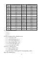
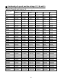
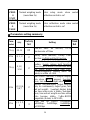
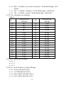
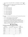
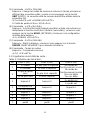
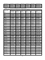
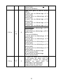
5.7) P7.xy: calibration resolution
Table2:

13
xy
calibration resolution
xy
calibration resolution
00
500
16
7500
01
600
17
8000
02
750
18
10000
03
800
19
12000
04
1000
20
15000
05
1200
21
20000
06
1500
22
25000
07
2000
23
30000
08
2400
24
35000
09
2500
25
40000
10
3000
26
50000
11
3500
27
60000
12
4000
28
70000
13
5000
29
75000
14
6000
30
80000
15
7000
31
100000
5.8) P8.x: calibration division
x = 0 : 1
x = 1 : 2
x = 2 : 5
5.9) P9.x: decimal point in calibration mode
x = 0 : no decimal (x100)
x = 1 : one decimal digit (x10–1)
x = 2 : two decimal digits (x10–2)
x = 3 : three decimal digits ( x10–3)
x = 4 : four decimal digits (x10–4)
x = 5 : no decimal point (x10 1)
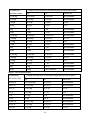
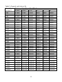
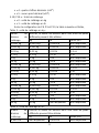
5.10) P10.x: Calibration unit
x = 0 : kg as calibration unit
x = 1 : lb as calibration unit
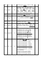
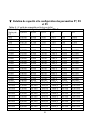
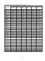
As per the setting of P8, P9 and P10, following table is listed,
Table3: Kg calibration unit:

14
Calibration
division value
Display division value in different weight unit that can be used
kg
lb
Lb:oz (oz)
0.0001kg
0.0001kg
0.0002lb
Not available
0.001kg
0.001kg
0.002lb
Not available
0.01kg
0.01kg
0.02lb
0.5oz
0.1kg
0.1kg
0.2lb
5 oz
1kg
1kg
2lb
Not available
10kg
10kg
20 lb
Not available
0.0002kg
0.0002kg
0.0005 lb
Not available
0.002kg
0.002kg
0.005 lb
0.1 oz
0.02kg
0.02kg
0.05 lb
1 oz
0.2kg
0.2kg
0.5 lb
Not available
2kg
2kg
5 lb
Not available
20kg
20kg
50 lb
Not available
0.0005kg
0.0005kg
0.001 lb
Not available
0.005kg
0.005kg
0.01 lb
0.2 oz
0.05kg
0.05kg
0.1 lb
2oz
0.5kg
0.5kg
1 lb
Not available
5kg
5kg
10 lb
Not available
50kg
50kg
Not available
Not available
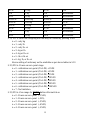
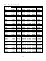
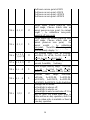
Table4: Lb calibration unit:
Calibration
division value
Display division value in different weight unit that can be used
kg
lb
Lb:oz (oz)
0.0001lb
Not available
0.0001lb
Not available
0.001 lb
0.0005 kg
0.001 lb
Not available
0.01 lb
0.005 kg
0.01 lb
0.2 oz
0.1 lb
0.05 kg
0.1 lb
2 oz
1 lb
0.5 kg
1 lb
Not available
10 lb
5 kg
10 lb
Not available
0.0002 lb
0.0001 kg
0.0002 lb
Not available
0.002 lb
0.001 kg
0.002 lb
Not available
0.02 lb
0.01 kg
0.02 lb
0.5 oz

15
0.2 lb
0.1 kg
0.2 lb
5 oz
2 lb
1 kg
2 lb
Not available
20 lb
10 kg
20 lb
Not available
0.0005 lb
0.0002 kg
0.0005 lb
Not available
0.005 lb
0.002 kg
0.005 lb
0.1 oz
0.05 lb
0.02 kg
0.05 lb
1 oz
0.5 lb
0.2 kg
0.5 lb
Not available
5 lb
2 kg
5 lb
Not available
50 lb
20 kg
50 lb
Not available
5.11) P11.x: select the weighing unit that may be chosen by pressing UNIT
x = 0 : only kg
x = 1 : only lb
x = 2 : only lb: oz
x = 3 : kg or lb
x = 4 : kg or lb: oz
x = 5 : lb or lb: oz
x = 6 : kg, lb, or lb: oz
Above setting of units may not be available as per above tables in 5.10
5.12) P12.x: Power-on zero-point range
x = 0 : calibration zero point (CAL.P0) +1%FS
x = 1 : calibration zero point (CAL.P0) +2%FS
x = 2 : calibration zero point (CAL.P0) +5%FS
x = 3 : calibration zero point (CAL.P0) +10%FS
x = 4 : calibration zero point (CAL.P0) +20%FS
x = 5 : calibration zero point (CAL.P0) +50%FS
x = 6 : calibration zero point (CAL.P0) +100%FS
x = 7 : No limitation
5.13) P13.x: Zero range for ZERO button after switch on
x = 0 : Power-on zero-point ±1%FS;
x = 1 : Power-on zero-point ±2FS;
x = 2 : Power-on zero-point ±3%FS;
x = 3 : Power-on zero-point ±4%FS;
x = 4 : Power-on zero-point ±5%FS;
La page est en cours de chargement...
La page est en cours de chargement...
La page est en cours de chargement...
La page est en cours de chargement...
La page est en cours de chargement...
La page est en cours de chargement...
La page est en cours de chargement...
La page est en cours de chargement...
La page est en cours de chargement...
La page est en cours de chargement...
La page est en cours de chargement...
La page est en cours de chargement...
La page est en cours de chargement...
La page est en cours de chargement...
La page est en cours de chargement...
La page est en cours de chargement...
La page est en cours de chargement...
La page est en cours de chargement...
La page est en cours de chargement...
La page est en cours de chargement...
La page est en cours de chargement...
La page est en cours de chargement...
La page est en cours de chargement...
La page est en cours de chargement...
La page est en cours de chargement...
La page est en cours de chargement...
La page est en cours de chargement...
La page est en cours de chargement...
La page est en cours de chargement...
La page est en cours de chargement...
La page est en cours de chargement...
La page est en cours de chargement...
La page est en cours de chargement...
La page est en cours de chargement...
La page est en cours de chargement...
La page est en cours de chargement...
La page est en cours de chargement...
La page est en cours de chargement...
La page est en cours de chargement...
La page est en cours de chargement...
La page est en cours de chargement...
La page est en cours de chargement...
La page est en cours de chargement...
La page est en cours de chargement...
La page est en cours de chargement...
La page est en cours de chargement...
La page est en cours de chargement...
La page est en cours de chargement...
La page est en cours de chargement...
-
 1
1
-
 2
2
-
 3
3
-
 4
4
-
 5
5
-
 6
6
-
 7
7
-
 8
8
-
 9
9
-
 10
10
-
 11
11
-
 12
12
-
 13
13
-
 14
14
-
 15
15
-
 16
16
-
 17
17
-
 18
18
-
 19
19
-
 20
20
-
 21
21
-
 22
22
-
 23
23
-
 24
24
-
 25
25
-
 26
26
-
 27
27
-
 28
28
-
 29
29
-
 30
30
-
 31
31
-
 32
32
-
 33
33
-
 34
34
-
 35
35
-
 36
36
-
 37
37
-
 38
38
-
 39
39
-
 40
40
-
 41
41
-
 42
42
-
 43
43
-
 44
44
-
 45
45
-
 46
46
-
 47
47
-
 48
48
-
 49
49
-
 50
50
-
 51
51
-
 52
52
-
 53
53
-
 54
54
-
 55
55
-
 56
56
-
 57
57
-
 58
58
-
 59
59
-
 60
60
-
 61
61
-
 62
62
-
 63
63
-
 64
64
-
 65
65
-
 66
66
-
 67
67
-
 68
68
-
 69
69


Brecknell 816965004812 Manuel utilisateur
- Taper
- Manuel utilisateur
dans d''autres langues
- English: Brecknell 816965004812 User manual
Documents connexes
Autres documents
-
Adam Equipment GBK 120 Manuel utilisateur
-
-
 Giropes Baxtran BAR150I Manuel utilisateur
-
-
-
-
Ohaus cd-11 Manuel utilisateur
-
Soehnle 7710 Manuel utilisateur
-
Steinberg SBS-KW-300/100 Manuel utilisateur
