MULTIPLEX Easyglider Building Instructions
- Catégorie
- Jouets
- Taper
- Building Instructions

1
GB
D
E
I
Bauanleitung 03 ... 10
Building instructions 11 ... 19
Notice de construction 20 ... 34
Istruzioni di montaggio 35 ... 42
Instrucciones de montaje 43 ... 50
© Copyright by MULTIPLEX 2005 Version 3.0
KIT EasyGlider # 21 4205
KIT EasyGlider Electric # 21 4207
F

2
D
F
GB
I
E
Sicherheitshinweise
☺ Prüfen Sie vor jedem Start den festen Sitz des Motors und der Luftschraube - insbesondere nach dem Transport, härteren Landungen
sowie Abstürzen. Prüfen Sie ebenfalls vor jedem Start den festen Sitz und die richtige Position der Tragflächen auf dem Rumpf.
☺ Akku erst einstecken, wenn Ihr Sender eingeschaltet ist und Sie sicher sind, daß das Bedienelement für die Motorsteuerung auf
"AUS" steht.
☺ Im startbereiten Zustand nicht in den Bereich der Luftschraube greifen.
Vorsicht in der Luftschraubendrehebene - auch Zuschauer zur Seite bitten!
☺ Zwischen den Flügen die Motortemperatur durch vorsichtige Fingerprobe prüfen und
vor einem Neustart den Motor ausreichend abkühlen lassen. Die Temperatur ist richtig, wenn Sie den Motor problemlos berühren
können. Insbesondere bei hohen Außentemperaturen kann dieses bis zu 15 Minuten dauern.
☺ Denken Sie immer daran: Niemals auf Personen und Tiere zufliegen.
Conseils de sécurité
☺ Avant chaque décollage, vérifiez la fixation du moteur et de l'hélice, notamment après le transport, après les atterrissages violents
et après un “Crash”. Vérifiez également, avant chaque décollage la fixation ainsi que le positionnement de l’aile par rapport au
fuselage.
☺ Ne branchez l’accu de propulsion que si vous êtes sûr que votre émetteur est allumé et que l’élément de commande moteur est en
position “ARRET”.
☺ Ne mettez pas vos doigts dans l’hélice! Attention à la mise en marche, demandez également aux spectateurs de reculer.
☺ Entre deux vols, vérifiez en posant un doigt dessus, la température du moteur, laissezle refroidir suffisamment avant le prochain
décollage. La température est correcte si vous pouvez maintenir votre doigt ou votre main sur le moteur. Le temps de refroidissement
peut varier jusqu’à 15 minutes s’il fait particulièrement chaud.
☺ Pensez-y toujours: ne volez jamais vers ou au-dessus des personnes ou des animaux.
Safety notes
☺ Before every flight check that the motor and propeller are in place and secure - especially after transporting the model, and after
hard landings and crashes. Check also that the wing is correctly located and firmly secured on the fuselage before each flight.
☺ Don’t plug in the battery until you have switched on the transmitter, and you are sure that the motor control on the transmitter is set
to “OFF”.
☺ When the model is switched on, ready to fly, take care not to touch the propeller. Keep well clear of the propeller disc too, and ask
spectators to stay back.
☺ Allow the motor to cool down after each flight. You can check this by carefully touching the motor case with your finger. The
temperature is correct when you can hold your finger on the case without any problem. On hot days this may take up to 15 minutes.
☺ Please keep in mind at all times: don’t fly towards people or animals.
Note di sicurezza
☺ Prima di ogni decollo controllare che il motore e la eliche siano fissati stabilmente - specialmente dopo il trasporto, atterraggi duri
e se il modello è precipitato. Controllare prima del decollo anche il fissaggio e la posizione corretta delle ali sulla fusoliera.
☺ Collegare la batteria solo quando la radio è inserita ed il comando del motore è sicuramente in posizione ”SPENTO”.
☺ Prima del decollo non avvicinarsi al campo di rotazione della eliche. Attenzione alla eliche in movimento - pregare che eventuali
spettatori si portino alla dovuta distanza di sicurezza!
☺ Tra un volo e l’altro controllare cautamente con le dita la temperatura del motore e farli raffreddare sufficientemente prima di ogni
nuovo decollo. La temperatura è giusta se si possono toccare senza problemi. Specialmente con una temperatura esterna alta
questo può durare fino a 15 minuti.
☺ Fare attenzione: Non volare mai nella direzione di persone ed animali.
Advertencias de seguridad
☺ Compruebe antes de cada despegue que el motor y la hélice estén fuertemente sujetados, sobretodo después de haberlo transportado,
de aterrizajes más fuertes así como después de una caída. Compruebe igualmente antes de cada despegue que las alas estén bien
sujetas y bien colocadas en el fuselaje.
☺ Conectar la batería, cuando la emisora esté encendida y Usted esté seguro que el elemento de mando para el motor esté en ”OFF”.
☺ No meter la mano en la zona inmediata a la hélice cuando el avión esté a punto de despegar. ¡Cuidado con la zona de la hélice!
¡Pedir a los espectadores que se aparten!
☺ Entre los vuelos hay que comprobar cuidadosamente la temperatura del motor con el dedo y dejar que el motor se enfríe antes de
volver a despegar. La temperatura es correcta, si puede tocar el motor sin problemas. Sobretodo en el caso de temperaturas del
ambiente muy altas, esto puede tardar unos 15 minutos.
☺ Recuerde: No volar nunca hacía personas o animales.

3
KIT EasyGlider # 21 4205
KIT EasyGlider Electric # 21 4207
Machen Sie sich mit dem Bausatz vertraut!
MULTIPLEX - Modellbaukästen unterliegen während der Produktion einer ständigen Materialkontrolle. Wir hoffen, dass Sie mit
dem Baukasteninhalt zufrieden sind. Wir bitten Sie jedoch, alle Teile (nach Stückliste) vor Verwendung zu prüfen, da bearbeitete
Teile vom Umtausch ausgeschlossen sind. Sollte ein Bauteil einmal nicht in Ordnung sein, sind wir nach Überprüfung gerne zur
Nachbesserung oder zum Umtausch bereit. Bitte senden Sie das Teil an unsere Modellbauabteilung und fügen Sie unbedingt
den Kaufbeleg und eine kurze Fehlerbeschreibung bei.
Wir arbeiten ständig an der technischen Weiterentwicklung unserer Modelle. Änderungen des Baukasteninhalts in Form, Maß,
Technik, Material und Ausstattung behalten wir uns jederzeit und ohne Ankündigung vor. Bitte haben Sie Verständnis dafür, dass
aus Angaben und Abbildungen dieser Anleitung keine Ansprüche abgeleitet werden können.
Achtung!
Ferngesteuerte Modelle, insbesondere Flugmodelle, sind kein Spielzeug im üblichen Sinne. Ihr Bau und Betrieb erfordert
technisches Verständnis, ein Mindestmaß an handwerklicher Sorgfalt sowie Disziplin und Sicherheitsbewusstsein. Fehler
und Nachlässigkeiten beim Bau und Betrieb können Personen- und Sachschäden zur Folge haben. Da der Hersteller keinen
Einfluss auf ordnungsgemäßen Zusammenbau, Wartung und Betrieb hat, weisen wir ausdrücklich auf diese Gefahren hin.
Zusätzlich zum Modell EasyGlider / EasyGlider Electric erforderlich:
Klebstoff und zugehöriger Aktivator:
Sekundenkleber „leicht verdickt“ (Cyanacrylat-Kleber) in Verbindung mit Aktivator verwenden - keinen Styropor-Sekundenkleber!
Epoxy Klebstoffe geben eine zunächst subjektiv brauchbare Verbindung, jedoch platzt der harte Kleber bei Belastung von den
Teilen ab. Die Verbindung ist nur oberflächlich.
Alternativ kann auch Heisskleber verwendet werden!
MULTIPLEX Fernsteuerelemente für EasyGlider und EasyGlider Electric:
Empfänger PiCO 5/6 UNI 35 MHz z.B. A-Band Best.-Nr. 5 5920
alternativ 40 MHz Best.-Nr. 5 5921
oder Empfänger Micro IPD UNI 35 MHz z.B. A-Band Best.-Nr. 5 5971
alternativ 40 MHz Best.-Nr. 5 5972
Servo Tiny-S UNI (2x erforderlich) Höhe / Seite Best.-Nr. 6 5121
Servo Nano-S UNI (2x erforderlich) 2x Quer Best.-Nr. 6 5120
Verlängerungskabel 600 mm UNI Querruderservo 2x Best.-Nr. 8 5032
ggf. Trennfilterkabel 200 mm UNI Querruderservo 2x Best.-Nr. 8 5035
Ladegerät:
MULTIcharger 5008 DC (Ladestrom 100mA ...5A) 1.....8 Zellen NiCd/NiMh Best.-Nr. 9 2525
oder MULTIcharger LN-2010 (Ladestrom 200mA ...2A) 1...10 Zellen NiCd/NiMhBest.-Nr. 9 2523
beide zum Anschluss an 12V (z.B. Autobatterie) und 1...4 Zellen Lithium-Polymer
Zusätzlich nur für EasyGlider Electric -- siehe auch Seite 51 --
MULTIcont X-16 UNI Fahrtregler Best.-Nr. 7 2271
MULTIPLEX Antriebsakku Permabatt NiMh (AA-Mignon) 7 / 1500 mAh Best.-Nr. 15 6030
oder MULTIPLEX Antriebsakku Permabatt NiMh (AA-Mignon) 8 / 1500 mAh Best.-Nr. 15 6037
MULTIPLEX Antriebsakku Li-Batt (LiPo) 2 / 1-1250 mAh Best.-Nr. 15 7021
oder MULTIPLEX Antriebsakku Li-Batt (LiPo) 2 / 1-2000 mAh Best.-Nr. 15 7016
ggf. Stecker für Verbindung Fahrtregler - Antriebsakku 6 Pol / grün Best.-Nr. 8 5213
Zusätzlich nur für EasyGlider
Empfängerakku (NiMh) 4 / 1500mAh Best.-Nr. 15 6029
Mini - Schalterkabel mit Ladebuchse Best.-Nr. 8 5037
Werkzeuge:
Schere, Klingenmesser, Seitenschneider, Lötkolben.
Hinweis: Bildseiten aus der Mitte der Bauanleitung heraustrennen!
Technische Daten: EasyGlider EasyGlider Electric
Spannweite 1.800 mm 1.800 mm
Länge über alles 1.130 mm 1.115 mm
Rumpflänge 1.060 mm 1.020mm
Fluggewicht ca. 710 g mit Serienantrieb ca. 880 g
Flächeninhalt FAI ca. 41,6 dm² FAI ca. 41,6 dm²
Flächenbelastung ca. 17 g/dm² ca. 21 g/dm²
RC-Funktionen Höhen-, Seiten- und Querruder zusäzlich Motorsteuerung
D

4
Wichtiger Hinweis
Dieses Modell ist nicht aus Styropor ™! Daher sind Verkle-
bungen mit Weißleim oder Epoxy
nicht möglich. Verwenden
Sie nur Cyanacrylatkleber (Sekundenkleber), vorzugsweise
in Verbindung mit Aktivator (Kicker). Für alle Verklebungen
verwenden Sie Cyanacrylatkleber in mittlerer Viskosität.
Sprühen Sie bei Elapor® immer eine Seite mit Aktivator (Kik-
ker) ein – lassen diesen 2 Minuten ablüften und geben Sie
auf die andere Seite den Cyanacrylatkleber an. Fügen Sie die
Teile zusammen und positionieren Sie diese
sofort.
Vorsicht beim Arbeiten mit Cyanacrylatklebern. Diese Kle-
ber härten in Sekunden, daher nicht mit den Fingern und an-
deren Körperteilen in Verbindung bringen. Zum Schutz der
Augen unbedingt Schutzbrille tragen! Von Kindern fernhal-
ten!
1. Vor dem Bau
Prüfen Sie den Inhalt Ihres Baukastens.
Dazu sind die Abb. 1+2 und die Stückliste hilfreich.
Beachten Sie, dass beim Seglermodell teilweise andere Teile
beiliegen als beim Elektromodell.
Fertigstellung des Rumpfes und der Leitwerke
2. Vorbereitung der Bowdenzüge
Die Länge der Höhenruder-Bowdenzugrohre 43 und 45
kontrollieren und ggf. kürzen.
43 Ø 3/2 x 810 mm
45 Ø 2/1 x 850 mm
Stahl 41 Ø 0,8 x 890 mm einstecken!
Ebenso mit den Seitenruder-Bowdenzugrohren 44 und 46
verfahren.
44 Ø 3/2 x 785 mm
46 Ø 2/1 x 810 mm
Stahl 42 Ø 0,8 x 850 mm einstecken!
3. Einbau der Bowdenzüge in die Rumpfhälften
Achtung: Durch die sorgfältige Verklebung der Bowdenzug-
aussenrohre 43 und 44 sowie dem Antennenrohr 47 auf der
gesamten Länge mit dem Rumpf entsteht ein erheblicher
Stabilitätszuwachs am Leitwerksträger.
Achten Sie auch auf die Leichtgängigkeit der Bowdenzüge und
dass kein Klebstoff in das Bowdenzugrohr gelangt.
Linke Rumpfhälfte:
Höhenruder-Bowdenzug (Stahldrahtlänge = 890mm) mit der
Z-Biegung voraus in die linke Rumpfhälfte stecken.
Abb. 3
Bowdenzugaussenrohr 43 vorne in der Rumpfhälfte nach Abb.
4 bündig positionieren. Rumpfhälfte flach auflegen und mit
Sekundenkleber das Aussenrohr 43 auf der gesamten Nut-
länge der Rumpfhälfte festkleben.
Abb. 5
Rechte Rumpfhälfte:
Seitenruder-Bowdenzug (Stahldrahtlänge = 850mm) mit der Z-
Biegung voraus in die rechte Rumpfhälfte stecken.
Abb. 6
Bowdenzugaussenrohr 44 vorne in der Rumpfhälfte nach Abb.
7 bündig positionieren. Rumpfhälfte flach auflegen (achten Sie
auf die Arretierzapfen / Rumpfhälfte über Eck flach auf den Tisch
legen) und mit Sekundenkleber das Aussenrohr 44 auf der
gesamten Aussennut der Rumpfhälfte festkleben.
Abb. 8
4. Antennenrohr einbauen
Antennenrohr 47 in die rechte Rumpfhälfte kleben - Rumpf dabei
nicht verbiegen! Abb. 9
5. Hochstarthaken einbauen (nur beim Segler)
Beim Segelflugmodell wird nun der Hochstarthaken 32 in das
Formnest der Rumpfhälfte 4 geklebt.
Abb. 9
Am Seitenruder 13 mit einem scharfen Klingenmesser die
daran angebundene Motorarretierung 13.1 an den in der
Zeichnung gestrichelten Linien abschneiden.
Abb. 10
6. Servos in die Rumpfhälften einbauen
Stellen Sie die Servos mit der Fernsteuerung auf „Neutral“ und
montieren Sie die Servohebel so auf den Servos, dass sie 90°
zum Servo stehen.
Die Servos wie gezeigt seitlich in die linke und rechte
Rumpfhälfte stecken. Bei Verwendung von anderen Servos, kön-
nen kleinere Anpassarbeiten notwendig werden. Die Servo-
kabel von unten nach oben in die Aussparung legen und mit
einem Tropfen Heisskleber fixieren. Ebenso die Servos mit
einem Tropfen Heisskleber an den Laschen der Servos
befestigen.
Abb. 12+13
7. Zusammenkleben der Rumpfhälften
Geeigneter Kleber für diese Verbindung ist CA Kleber dickflüs-
sig (Sekundenkleber) in Verbindung mit Aktivator.
Achtung: Bei der Elektroversion wird zuvor noch das Aus-
gleichsgewicht 33 wie in Abb. 11E gezeigt eingeklebt und die
Motorarretierung 13.1 eingesteckt.
Jetzt noch die Motor/Getriebeeinheit 14 einsetzen. Empfehlens-
wert ist, den Motorregler bereits zuvor am Motor anzulöten.
Abb. 11E
Hinweis: Die Motor/Getriebeeinheit lässt sich bei Bedarf auch
nachträglich wieder aus dem Rumpf entnehmen. Vorausset-
zung dafür ist, dass der Spinner und Mitnehmer abmontiert
werden und die Motor/Getriebeeinheit nicht mit Klebstoff in Ver-
bindung gekommen ist. Der Antrieb kann nach herunterdrük-
ken der Motorarretierung 13.1 nach hinten entnommen wer-
den.
Die Rumpfhälften 3 / 5 und 4 / 6 +13.1 werden zunächst noch
ohne Klebstoff geprüft, ob sich diese einwandfrei fügen lassen
– ggf. an entsprechender Stelle nacharbeiten.
Rumpfhälfte 4 / 6 mit Aktivator einsprühen und 2min. ablüften
lassen.
Rumpfhälfte 3 / 5 an den Verbindungsstellen mit Klebstoff ver-
sehen und mit 4 / 6 sorgfältig fügen und ausrichten! Die Rumpf-
naht muss gerade verlaufen und darf nicht gebogen sein!
Abb. 14
8. Kabinenhaubenverschluss einbauen
In den Rumpf die Verschlussklammern 22 für die Kabinen-
haubenbefestigung Canopy-Lock so einbauen, dass der
Verschlusszapfen 23 später zwischen der Klammer 22 und
Rumpfwand eingerastet werden kann. Dazu die „Nester“ im
Rumpf mit Aktivator einsprühen und ablüften lassen. Dann die
Klebeflächen der Verschlussklammern mit Sekundenkleber
einstreichen und sofort positioniert einsetzen. Ggf. später nach-
kleben.
Abb. 15
9. Seitenruderscharnier einbauen
Das Scharnier 31 mit wenig Sekundenkleber im Rumpfende
einkleben. Achten Sie insbesondere darauf, dass kein Kleber
in das Scharnier kommt.
Abb. 16
An der Vorderkante des Seitenruders mittig mit einem Klingen-
messer den Ausschnitt für das Ruderscharnier 31 ausschnei-
den. Bitte Vorsicht! Verletzungsgefahr. Den Schlitz im Ruder

5
nach unten ca. 3 bis 4mm länger schneiden, damit Seiten- und
Höhenruder später bequem auf dem Rumpf montiert werden
können.
Abb. 17
10. Ruderhorn am Seitenruder befestigen
Das T-Stück des Ruderhorns 24 für das Seitenruder 13 auf ca.
2mm kürzen (Seitenschneider). Gestängeanschluss 25 in die
zweite Bohrung von aussen in das Ruderhorn 24 stecken und
mit der U-Scheibe 26 und der Mutter 27 befestigen. Achtung:
Beachten Sie die Einbaurichtung! Die Mutter vorsichtig so an-
ziehen, dass der Gestängeanschluss nicht wackelt und nicht
klemmt. Anschliessend mit einem Abstrich (Nadel) Sekunden-
kleber sichern. Den Inbusgewindestift 28 mit dem Inbusschlüs-
sel 29 im Gestängeanschluss 25 vormontieren.
Das Ruderhorn 24 - mit der Lochreihe zur Scharnierlinie zei-
gend - in das zuvor mit Aktivator benetzte Nest des Seitenru-
ders einkleben.
Abb. 18
11. Höhen- und Seitenruder gängig machen
Am Höhenleitwerk 12 das Höhenruder seitlich frei schneiden
(1 mm Schlitz). Die Scharnierkanten von Seiten- und Höhenru-
der durch hin- und herbewegen „gängig“ machen - keinesfalls
das Ruder abtrennen!
Abb. 19
12. Ruderhorn am Höhenruder befestigen
Gestängeanschluss 25 in äusserste Bohrung in das Ruder-
horn 24 stecken und mit der U-Scheibe 26 und der Mutter 27
befestigen. Achtung: Beachten Sie die Einbaurichtung! Die
Mutter mit Gefühl anziehen und anschliessend mit einem Ab-
strich (Nadel) Sekundenkleber sichern. Den Inbusgewindestift
28 mit dem Inbusschlüssel 29 im Gestängeanschluss 25 vor-
montieren.
Das Ruderhorn 24 - mit der Lochreihe zur Scharnierlinie zei-
gend - in das zuvor mit Aktivator benetzte Nest des Höhenru-
ders einkleben.
Abb. 20
13. Höhen- und Seitenleitwerk verkleben
Höhenleitwerk 12 und das Seitenleitwerk 13 im 90° Winkel mit-
einander verkleben. Verwenden Sie zur Überprüfung z.B. ein
Geo-Dreieck.
Abb. 21
14. Leitwerke mit dem Rumpf verkleben
Das Höhen- und Seitenleitwerk probehalber noch ohne Kleb-
stoff auf dem Rumpf positionieren und die Passgenauigkeit
überprüfen. Dabei zuerst das Scharnier 31 im Seitenruder 13
ansetzen und die Leitwerke anschliessend nach vorne in Po-
sition bringen. Achten Sie hier besonders darauf, dass das
Höhenleitwerk 12 spaltfrei auf dem Rumpf aufliegt und parallel
zur Tragflächenauflage - vorne im Rumpf - ist. Der Holmverbin-
der 40 wird hierzu als Hilfsmittel quer im Tragflächenausschnitt
positioniert (z.B. mit Kreppband sichern). Nun von der Rumpf-
nase her über den Holmverbinder peilen und so das Höhen-
leitwerk ausrichten. Wenn sich die Leitwerke so ausrichten las-
sen werden diese mit dem Rumpf verklebt. Ausrichtung und
Spaltfreiheit nochmals überprüfen! Wenn Sie hier nicht genau
arbeiten, werden Sie sich ein Modellflugzeugleben lang dar-
über ärgern.
Abb. 21
15. Höhen- und Seitenrudergestänge arretieren
Die Stahldrahtenden 42 und 43 durch die Gestängeanschlüsse
25 führen - Servos und Ruder auf Neutral stellen und mit den
Inbus-Gewindestiften 28 festklemmen.
Abb. 22 + 23
Fertigstellung der Tragflächen
16. Querruder gängig machen
An den Tragflächen 8 und 9 die Querruder seitlich freischneiden
(1 mm Spalt). Die Scharnierkanten durch hin- und herbewegen
„gängig“ machen - keinesfalls die Ruder abtrennen!
Abb. 24
17. Ruderhörner am Querruder befestigen
In die beiden Ruderhörner für die Querruder die Gestängean-
schlüsse 25 in die äusserste Bohrung der Ruderhörner 24
stecken. Mit den U-Scheiben 26 und den Muttern 27 befesti-
gen. Achtung: 1x links und 1x rechts! Die Muttern mit Gefühl
anziehen und anschliessend mit einem Abstrich (Nadel)
Sekundenkleber sichern. Den Inbusgewindestift 28 mit dem
Inbusschlüssel 29 im Gestängeanschluss 25 vormontieren.
Die Ruderhörner 24 - mit der Lochreihe zur Scharnierlinie zei-
gend - in das zuvor mit Aktivator benetzte Nest der Querruder
einkleben.
Abb. 25
18. Querruderservos montieren
Stellen Sie die Servos mit der Fernsteuerung auf „Neutral“. Mon-
tieren Sie die Servohebel so auf den Servos, dass die Hebel in
Neutralstellung 90° seitlich überstehen - 1x links und 1x rechts
(also gespiegelt).
Die Servos in die Formnester der Tragflächen 8 und 9
einpassen. Dem verwendeten Servotyp entsprechend, können
kleinere Anpassarbeiten notwendig werden. Zum Einkleben
jeweils einen Tropfen Heisskleber in die Schlitze für die
Servolaschen am Flügel angeben und das Servo sofort in das
Nest drücken - ggf. anschliessend nachkleben.
Abb. 25
19. Querrudergestänge montieren
Stahldrähte 30 mit der Z-Biegung im äusseren Loch des
Servohebels einhängen und durch den Gestängeanschluss
25 stecken. Ruder und Servo in Neutralstellung bringen und
mit dem Gewindestift 28 festklemmen.
Abb. 26
20. Querruderservokabel verlegen
Das Servokabel im Bogen in Richtung Holmverbinderschacht
verlegen und dort mit dem 600mm Verlängerungskabel verlän-
gern. Die Kabel können gelötet oder mit den serienmässigen
Steckverbindern verbunden werden. Für die Steckverbindung
selbst ist eine Aussparung in der Holmabdeckung 10 und 11
vorgesehen. Das Kabel nun geradlinig und hochkant stehend
an der Vorderkante des Holmschachts festlegen. Das Kabel
muss an der Flügelwurzel ca. 250mm überstehen, damit es
bei der Montage des Modells in den Rumpf gezogen und im
Empfänger eingesteckt werden kann.
Abb. 26
21. Holmabdeckungen einkleben
Die Holmabdeckungen 10 und 11 sorgfältig in die Tragflächen
8 und 9 einpassen. An der Steckverbindung des Servover-
längerungskabels ggf. etwas freischneiden. Wenn sich die
Holmabdeckungen vollständig einbauen lassen können die-
se mit Sekundenkleber eingeklebt werden. Achten Sie insbe-
sondere darauf, dass kein Klebstoff auf die Flächen gelangt,
in die später der Holmverbinder 40 gesteckt wird. Probieren
Sie den Holmverbinder 40 erst aus, wenn Sie sicher sind, dass
innerhalb der Steckung kein aktiver Kleber mehr ist (sicher-
heitshalber Aktivator einspritzen und ca. 5 Minuten warten).
Sonst kann es passieren, dass Sie das Modell nie wieder de-
montieren können.
Abb. 27

6
22. Tragflächen-Steckung überprüfen
Montieren Sie das Modell mit dem Holmverbinder 40. Die Ka-
bel der Querruder werden durch die Aussparung im Rumpf
nach vorne durchgezogen (ein selbstgemachter Durchzieh-
haken aus Stahldraht erleichtert das Einziehen). Überprüfen
Sie den korrekten Sitz (formschlüssig)der Tragflächen 8 und 9
im Rumpf. Ggf. vorsichtig folgendermassen nacharbeiten: Trag-
flächen an der Einführungskante zum Rumpf zwischen den
Fingern vorsichtig zusammendrücken.
Hinweis: Die Tragflächen werden nicht mit dem Rumpf ver-
klebt. Das Modell kann daher transportfreundlich zerlegt wer-
den.
Abb. 28
23. Kabinenhauben-Verschlusszapfen einkleben
Die beiden Verschlusszapfen 23 werden in die Kabinenhaube
7 eingesetzt – Zapfen zueinander nach innen zeigend! An die
Verzahnung dickflüssigen Sekundenkleber angeben - jetzt kein
Aktivator! -, dann die Verschlusszapfen in die Schlitze der Kabi-
nenhaube einsetzen. Die Kabinenhaube in den Rumpf einfüh-
ren und mit den Verschlusszapfen in die Verschlussklammern
22 einschnappen lassen. Sofort am Rumpf ausrichten. Etwa 1
Minute warten und die Haube anschliessend vorsichtig öffnen.
Die Klebestellen an den Verschlusszapfen mit Aktivator ein-
sprühen. Bei der Segler-Variante wird der vordere Niederhalter
der Kabinenhaube je nach Akkugröße mit dem Klingenmesser
angepasst.
Abb. 29+30
Fernsteuerungseinbau allgemein
Im Kabinenbereich sind jetzt noch die fehlenden Fernsteuer-
komponenten einzubauen. Achten Sie bereits bei der Positio-
nierung von Empfänger und Akku auf die angegebene Schwer-
punktvorgabe. Durch Verschieben der Akkus sind Schwerpunkt-
korrekturen möglich.
Für die Befestigung der Bauteile liegt Klettband mit Haken-
und Veloursseite 20+21 bei. Der Haftkleber des Klettbands ist
nicht ausreichend, daher das Band im Rumpf zusätzlich mit
Sekundenkleber festkleben.
Hinter den Servos wird bei beiden Versionen der Empfänger
mit Klettband platziert. Das Antennenkabel in das bereits ein-
gebaute Kunststoffrohr 47 einziehen. Das geht am einfachsten
mit einem angespitzten Stahldraht, der von hinten durch das
Rohr 47 gesteckt wird. Die Spitze in das Ende der Antennen-
isolierung einpieksen, ggf. zum Durchziehen mit etwas
Sekundenkleber sichern.
Abb. 31+32
Fernsteuerungseinbau beim Elektroflugmodell
Der beiliegende Antriebsmotor ist bereits intern vorentstört.
Diese Entstörung ist bei Verwendung des Reglers MULTIcont
X-16 # 7 2271 ausreichend.
Falls Sie andere Regler einsetzen, sollten Sie die Motor-Ent-
störung sicherheitshalber erweitern. Dazu ist ein passender
Entstörsatz # 8 5020 erhältlich. Löten Sie dazu je einen Kon-
densator 47 nF vom Motoranschluss zum Motorgehäuse und
einen Kondensator ebenfalls 47 nF über die Motoranschlüsse.
Den Regler an die Lötfahnen des Motors anlöten.
Plus-Pol Regler an Minus-Pol Motor
Minus-Pol Regler an Plus-Pol Motor
Das einstufige Getriebe macht das Umpolen des Motors erfor-
derlich. Löten Sie kurz und mit gleichzeitiger Zugabe von Löt-
zinn - Antriebseinheit dazu ggf. nochmals ausbauen.
Der Regler wird hinter dem Motor an der Rumpfwand befestigt.
An der Anschlusseite des Akkus ist noch der entsprechende
Akkustecker anzulöten und die Lötstellen mit Schrumpfschlauch
zu isolieren.
Der Akku wird in das Fach hinter dem Empfänger unter den
Flügel geschoben. Je nach Akku klemmt sich dieser im Schacht
fest oder muss ggf. zusätzlich gesichert werden.
Stecken Sie nun probehalber alle Verbindungen entsprechend
der Anleitung der Fernsteuerung zusammen.
Montieren Sie die Luftschraubenblätter 14 mit jeweils einer
Distanzhülse und einer Schraube am Mitnehmer. Die Schrau-
ben vollständig, jedoch mit Gefühl festziehen (nicht überdre-
hen - es geht sehr leicht).
Abb. 31
Den Verbindungsstecker Akku / Regler für den Motor erst
einstecken, wenn Ihr Sender eingeschaltet ist und Sie si-
cher sind, dass das Bedienelement für die Motorsteuerung
auf „AUS“ steht.
Schalten Sie den Sender ein und verbinden Sie im Modell den
Antriebsakku mit dem Regler und den Regler mit dem Emp-
fänger. Es ist notwendig, dass Ihr Regler eine sogenannte BEC-
Schaltung besitzt (Empfängerstromversorgung aus dem Flug-
akku).
Nun kurz den Motor einschalten und nochmals die Drehrichtung
des Propeller kontrollieren (beim Probelauf Modell festhalten
und lose, leichte Gegenstände hinter dem Modell entfernen).
Vorsicht: Auch bei kleinen Motoren und Luftschrauben be-
steht erhebliche Verletzungsgefahr!
Fernsteuerungseinbau beim Segelflugmodell
Zusätzlich zum Empfänger wird noch das Schalterkabel und
der Empfängerakku eingebaut. Das Schalterkabel wird in den
seitlichen Schacht vor den Servos in die rechte Rumpfhälfte
gesteckt. Der Empfängerakku und den Boden in der Rumpf-
spitze mit Klettband versehen und den Akku einbauen.
Stecken Sie nun probehalber alle Verbindungen entsprechend
der Anleitung der Fernsteuerung zusammen.
Abschliessend den vorderen Verschlusszapfen der Kabinen-
haube 7 mit einem Klingenmesser an der Markierung kürzen
und ggf. nacharbeiten. Haube aufsetzen.
Abb. 32 + 30
Ruderausschläge einstellen
Um eine ausgewogene Steuerfolgsamkeit des Modells zu er-
zielen, ist die Größe der Ruderausschläge richtig einzustellen.
Die Ausschläge werden jeweils an der tiefsten Stelle der Ru-
der gemessen.
Höhenruder
nach oben - Knüppel gezogen - ca. +13mm
nach unten - Knüppel gedrückt - ca. - 13mm
Seitenruder
nach links und rechts je ca. 20mm
Querruder
nach oben ca. +20 mm
nach unten ca. - 8 mm
Spoiler - beide QR nach oben ca. +20 mm
Spoilerzumischung ins Höhenruder ca. - 5 mm
Abb. 33
Bei der Funktion „Spoiler“ können zur Verkürzung des Lande-
anfluges beide Querruder nach oben gestellt werden. Gleich-
zeitig wird dazu ein entsprechender Tiefenruderausschlag zu-
gemischt um das Modell im stabilen Flugzustand zu halten.
Vorraussetzung dazu ist eine Fernsteuerung mit entsprechen-
den Mixern.
Lesen Sie hierzu in der Anleitung der Fernsteuerung.

7
Hinweis: Bei Querruder rechts bewegt sich das in Flugrichtung
gesehen rechte Querruder nach oben.
Falls Ihre Fernsteuerung die oben angegebenen Wege nicht
zulässt, müssen Sie ggf. den Gestängeanschluss umsetzen.
Noch etwas für die Schönheit
Dem Bausatz liegt ein mehrfarbiger Dekorbogen bei. Die ein-
zelnen Schriftzüge und Embleme werden ausgeschnitten und
nach unserer Vorlage (Baukastenbild) oder nach eigenen Vor-
stellungen aufgebracht. Die Kabinenhaube 5 wird mit einem
wasserfesten Filzschreiber (z.B. Edding 3000) bis zum Rand
geschwärzt.
Auswiegen des Schwerpunkts
Um stabile Flugeigenschaften zu erzielen, muss Ihr EasyGlider/
Electric, wie jedes andere Flugzeug auch, an einer bestimm-
ten Stelle im Gleichgewicht sein. Montieren Sie Ihr Modell flug-
fertig. Korrekturen sind durch Verschieben von Empfänger-
akku bzw. Antriebsakku möglich. Falls dies noch nicht aus-
reicht, stellen Sie den Schwerpunkt, durch Zugabe von Trimm-
blei an entsprechender Stelle, ein
Der Schwerpunkt wird mit 70mm von der Vorderkante des Trag-
flügels am Rumpf gemessen und auf der Flügelunterseite mit
einem wasserfesten Stift angezeichnet.
Hier mit den Fingern unterstützt, soll das Modell waagerecht
auspendeln. Durch Verschieben des Antriebs- bzw. Empfänger-
akkus sind Korrekturen möglich. Ist die richtige Position gefun-
den, stellen Sie durch eine Markierung im Rumpf sicher, dass
der Akku immer an der selben Stelle positioniert wird.
Abb. 34
Vorbereitungen für den Erstflug
Für den Erstflug warten Sie einen möglichst windstillen Tag
ab. Besonders günstig sind oft die Abendstunden.
Wenn Sie noch keine Erfahrung im Modellflug haben, suchen
Sie sich einen geübten Helfer. Ganz allein geht es wahrschein-
lich „schief“. Kontakte finden Sie bei den örtlichen Modellflug-
vereinen. Nach Adressen können Sie Ihren Händler befragen.
Eine Hilfe für erste „Gehversuche“ ist auch unser Flugsimulator
für den PC.
Den Simulator können Sie sich kostenlos von unserer Home-
page www.multiplex-rc.de herunterladen. Das passende Inter-
face-Kabel für MPX-Sender erhalten Sie im Fachhandel (Best.-
Nr. # 8 5153).
Vor dem ersten Flug unbedingt einen Reichweitentest durch-
führen!
Sender- und Flugakku sind frisch und vorschriftsmäßig gela-
den. Vor dem Einschalten des Senders sicherstellen, dass der
verwendete Kanal frei ist.
Ein Helfer entfernt sich mit dem Sender und betätigt ständig
eine Steuerfunktion. Die Antenne ist dabei ganz eingeschoben.
Beobachten Sie die Servos. Die nicht gesteuerten Servos sol-
len bis zu einer Entfernung von ca. 60 m ruhig stehen. Das
gesteuerte Servo muss den Steuerbewegungen verzögerungs-
frei folgen. Dieser Test kann nur durchgeführt werden, wenn
das Funkband ungestört ist und keine weiteren Fernsteuer-
sender, auch nicht auf anderen Kanälen, in Betrieb sind! Der
Test muss beim EasyGlider Electric mit laufendem Motor wie-
derholt werden. Dabei darf sich die Reichweite nur unwesent-
lich verkürzen.
Falls etwas unklar ist, sollte auf keinen Fall ein Start erfolgen.
Geben Sie die gesamte Anlage (mit Akku, Schalterkabel,
Servos) in die Serviceabteilung des Geräteherstellers zur Über-
prüfung.
Erstflug ...
Segler:
Ein Gleitflug mit geradlinigem Wurf aus der Hand, gegen den
Wind, gibt erste Aufschlüsse ob das Modell richtig eingestellt
ist oder ob Trimmkorrekturen nötig sind. Wenn das Modell seit-
lich wegschiebt, trimmen Sie mit Seitenruder dagegen. Wenn
es sofort eine Tragfläche hängen lässt, ist eine Querruder-
korrektur notwendig.
Laufstart:
Die klassische Methode, ein Segelmodell in die Luft zu beför-
dern. Mit einem geeigneten Seil (liegt dem Bausatz bei) wird
das Modell durch einen Helfer, ähnlich wie beim Drachen stei-
gen lassen, hochgezogen. Dazu wird am Seilende der Hoch-
startring 52 und das Kontrollfähnchen 51 befestigt Abb.35.
Der Ring wird in den Hochstarthaken 32 eingeklinkt, das Seil
ausgerollt und der Helfer (Läufer) läuft am Seilende gegen
den Wind. Das Modell wird unter leichter Vorspannung freige-
geben. Der Helfer beobachtet beim Laufen das Modell. Es soll-
te gleichmässig steigen. Insbesondere bei stärkerem Wind
muss darauf geachtet werden, dass das Modell dabei nicht
überlastet wird.
Start am Gummiseil
Mit dieser Startart ist man bei dieser Modellgröße am Besten
bedient. Es ist kein Helfer nötig und die Ausgangshöhe beträgt
bereits ca. 100m. Aus dieser Höhe sind beachtliche Flugzeiten
erzielbar. Auch Thermikanschluss sollte bei entsprechender
Wetterlage kein Problem sein.
Thermikfliegen
Die Ausnutzung der Thermik setzt Erfahrung beim Piloten vor-
aus. Aufwindfelder sind in der Ebene - bedingt durch die größere
Flughöhe - am Flugverhalten des Modells schwerer zu erken-
nen als am Hang, wo "Bärte" meist in Augenhöhe gefunden und
ausgekreist werden können. Ein Aufwindfeld in der Ebene direkt
"über Kopf" zu erkennen und auszufliegen, ist nur den geübte-
sten Piloten möglich. Fliegen und suchen Sie deshalb immer
querab von Ihrem Standort.
Ein Aufwindfeld erkennen Sie am Flugverhalten des Modells.
Bei guter Thermik ist ein kräftiges Steigen erkennbar - schwa-
che Aufwindfelder erfordern ein geübtes Auge und das ganze
Können des Piloten. Mit einiger Übung werden Sie im Gelände
die Auslösepunkte für Thermik erkennen können. Die Luft wird
- je nach Rückstrahlkraft des Untergrundes mehr oder weniger
stark - erwärmt und fließt vom Wind getrieben dicht über den
Boden. An einer Geländerauhigkeit, einem Strauch, einem
Baum, einem Zaun, einer Waldkante, einem Hügel, einem
vorbeifahrenden Auto, sogar an Ihrem landenden Modellflug-
zeug wird diese Warmluft vom Boden abgelöst und steigt nach
oben. Ein schöner Vergleich im umgekehrten Sinne ist der
wandernde Wassertropfen an der Decke, der zunächst kleben
bleibt, gegen eine Rauhigkeit stößt und dann nach unten fällt.
Die markantesten Thermikauslöser sind z.B. scharf abgegrenz-
te Schneefelder an Berghängen. Über dem Schneefeld wird Luft
abgekühlt und fließt nach unten, am talseitigen Schneefeldrand
trifft diese auf hangaufwärts fließende Warmluft und löst diese
"messerscharf" ab. Steigstarke, allerdings auch ruppige
Thermikblasen sind die Folge. Die aufsteigende Warmluft gilt
es zu finden und zu "zentrieren". Dabei sollte das Modell durch
Steuerkorrekturen immer im Zentrum des Aufwindes gehalten
werden, dort sind die stärksten Steigwerte zu erwarten. Hierzu
ist jedoch einige Übung notwendig.
Um Sichtschwierigkeiten zu vermeiden, rechtzeitig die Steig-
zone verlassen. Denken Sie daran, dass das Modell unter einer
Wolke besser zu erkennen ist als im blauen, wolkenfreien
Bereich. Muss Höhe abgebaut werden, bedenken Sie:
Beim EasyGlider/Electric ist die Festigkeit für die Modellklasse

8
sehr hoch, jedoch auch hier endlich. Bei mutwilligen Zerstörungs-
versuchen dürfen Sie keine Kulanz erwarten.
Flug am Hang
Der Hangflug ist eine besonders reizvolle Art des Modellsegel-
fluges. Stundenlanges Fliegen im Hangwind ohne fremde
Hochstarthilfe gehört mit zu den schönsten Erlebnissen. Die
Krönung ist das Thermikfliegen vom Hang aus. Das Modell
abwerfen, hinausfliegen über das Tal, Thermik suchen, Ther-
mik finden, hochkreisen bis an die Sichtgrenze, das Modell im
Kunstflug wieder herunterbringen um das Spiel wieder neu zu
beginnen ist Modellflug in Vollendung.
Aber Vorsicht, der Hangflug birgt auch Gefahren für das Modell.
Zunächst ist die Landung in den meisten Fällen erheblich
schwieriger als in der Ebene. Es muss meist im verwirbelten
Lee des Berges gelandet werden. Dies erfordert Konzentration
und einen beherzten Anflug mit Überfahrt. Eine Landung im Luv,
also im unmittelbaren Hangaufwind, ist noch schwieriger, sie
sollte grundsätzlich hangaufwärts, mit Überfahrt und zeitlich
richtigem Abfangen kurz vor der Landung durchgeführt werden.
F-Schlepp
Ein Ideales Paar zum Schleppen und Schleppen lernen ist der
Magister und der EasyGlider. Wenn der Start vom Gras erfolgen
soll, brauchen Sie für den Magister einen stärkeren Motor. Z.B.
einen Brushless Außenläufer mit ca. 300 Watt Leistung.
Für den Schlepp benötigen Sie ein geflochtenes Seil mit ca. Ø
1 bis 1,5 mm, ca. 20 m lang. Am Ende wird ein gelochtes
Klettband befestigt. Die Gegenseite des Klettbands wird direkt
vorn unter den Rumpf des EasyGliders geklebt Abb.36. Am
Magister wird das andere Ende des Schleppseils mit einer
Schlaufe in die dafür vorgesehene Kupplung gehängt. Die
Modelle werden gegen den Wind hintereinander aufgebaut.
Das Schleppseil liegt auf dem Höhenleitwerk des Magisters.
Der Schlepper rollt an und strafft das Seil, erst jetzt wird Vollgas
gegeben - der Schleppzug beschleunigt - der Schlepper bleibt
am Boden - der Segler hebt ab, fliegt aber nur knapp über dem
Boden hinterher - nun hebt auch der Schlepper ab. Es wird
gleichmäßig (auch in den Kurven!!) gestiegen. Vermeiden Sie
bei den ersten Schlepps, Überflüge über Kopf. Zum Ausklinken
legen Sie den Segler in eine scharfe Kurve und ziehen kräftig
Höhenruder. Das Klettband löst sich und der Segler ist „frei“.
Elektroflug
Mit der Elektrovariante, dem EasyGlider Electric, haben Sie das
höchste Maß der Unabhängigkeit. Sie können in der Ebene aus
einer Akkuladung ca. 4 Steigflüge auf vernünftige Höhe machen.
Am Hang können Sie sich vor dem gefürchtetem „Absaufen“
schützen (Absaufen = wenn man im Tal landen muss, weil kein
Aufwind mehr gefunden wurde).
Flugleistung
Was ist Flugleistung beim Segelflugzeug?
Die wichtigsten Parameter sind die Sinkgeschwindigkeit und
der Gleitwinkel. Mit Sinkgeschwindigkeit wird das Sinken pro
Sekunde in der umgebenden Luft beschrieben. Die Sink-
geschwindigkeit wird in erste Linie von der Flächenbelastung
(Gewicht / Tragflächeninhalt) bestimmt. Hier hat der EasyGlider
ganz hervorragende Werte, deutlich bessere als bei herkömm-
lichen Modellen (nur ca. 17g/dm²). Daher muss die umgebende
Luft nur wenig steigen (Thermik) damit das Modell Höhe ge-
winnt. Zusätzlich wird die Fluggeschwindigkeit hauptsächlich
durch die Flächenbelastung bestimmt (je geringer um so lang-
samer). Dadurch kann das Modell extrem eng gekurvt werden
- das ist ebenfalls für das Thermikfliegen vorteilhaft (Thermik ist
in Bodennähe recht eng).
Nicht zuletzt kommt die geringe Fluggeschwindigkeit dem An-
fänger zu Gute. Er hat mehr Zeit zum Überlegen und das Modell
„verzeiht“ kleinere Steuerfehler.
Jedoch: „Wo Licht ist, ist auch Schatten!“
Der andere wichtige Parameter ist der Gleitwinkel. Er wird als
Verhältnis dargestellt d.h. aus einer bestimmten Höhe fliegt das
Modell so und so weit. Der Gleitwinkel wird mit steigender
Flächenbelastung grösser und natürlich auch die Fluggeschwin-
digkeit. Das wird notwendig , wenn bei grösserer Windgeschwin-
digkeit geflogen werden muss oder Durchzug für Kunstflug
benötigt wird.
Auch beim Thermikfliegen benötigen Sie Gleitwinkel. Hier sind
Abwindfelder zu überbrücken um wieder neue Aufwinde zu
finden. Zur Erhöhung der Flächenbelastung brauchen Sie
Ballast. Dieser sollte im Flügel platziert sein. Diesen Platz finden
wir im EasyGlider ideal. Es ist das GfK Rohr im Flügel. Der
Innendurchmesser beträgt 7,8 mm. Normal ist eine Ballast-
stange mit diesem Mass schwer zu finden und teuer. Zufällig
hat aber eine M8 Gewindestange das richtige Mass. Sie finden
diese preiswert in jedem Baumarkt. Sie hat Ø 7,7mm . In
einigen Fällen kommen Sie auch mit der halben Stange aus. In
diesem Fall muss die Stange gegen seitliches verrutschen
gesichert werden (z.B. von beiden Seiten Balsastangen ein-
schieben, um das Gewicht in der Mitte zu halten).
Sicherheit
Sicherheit ist oberstes Gebot beim Fliegen mit Flugmodellen.
Eine Haftpflichtversicherung ist obligatorisch. Falls Sie in einen
Verein oder Verband eintreten, können Sie diese Versicherung
dort abschließen. Achten Sie auf ausreichenden Versiche-
rungsschutz.
Halten Sie Modelle und Fernsteuerung immer absolut in Ord-
nung. Informieren Sie sich über die Ladetechnik für die von
Ihnen verwendeten Akkus. Benutzen Sie alle sinnvollen Sicher-
heitseinrichtungen, die angeboten werden. Informieren Sie
sich in unserem Hauptkatalog, MULTIPLEX - Produkte sind von
erfahrenen Modellfliegern aus der Praxis für die Praxis gemacht.
Fliegen Sie verantwortungsbewusst! Anderen Leuten dicht über
die Köpfe zu fliegen ist kein Zeichen für wirkliches Können, der
wirkliche Könner hat dies nicht nötig. Weisen Sie auch andere
Piloten in unser aller Interesse auf diese Tatsache hin. Fliegen
Sie immer so, dass weder Sie noch andere in Gefahr kommen.
Denken Sie immer daran, dass auch die allerbeste Fernsteue-
rung jederzeit durch äußere Einflüsse gestört werden kann.
Auch langjährige, unfallfreie Flugpraxis ist keine Garantie für die
nächste Flugminute.
Faszination
Modellfliegen ist nach wie vor ein faszinierendes Hobby mit
hohem Freizeitwert. Lernen Sie in vielen schönen Stunden in
freier Natur Ihren EasyGlider / Electric kennen, seine hervorra-
gende Leistungsfähigkeit und sein komfortables Flugverhalten.
Genießen Sie eine der wenigen Sportarten, in denen die Tech-
nik, das eigene Tun, das eigene Können alleine oder mit
Freunden und das Leben in und mit der Natur Erlebnisse
ermöglichen, die in der heutigen Zeit selten geworden sind,
Wir, das MULTIPLEX -Team, wünschen Ihnen beim Bauen und
später beim Fliegen viel Freude und Erfolg.
MULTIPLEX Modellsport GmbH &Co. KG
Produktbetreuung und Entwicklung
Klaus Michler

9
Stückliste
BK EasyGlider # 21 4205
BK EasyGlider Electric # 21 4207
Lfd. Stück Bezeichnung Material Abmessungen
1 1 1 Bauanleitung Papier DIN-A4
2 1 1 Dekorbogen bedruckte Klebefolie 350 x 1000mm
3 1 - Rumpfhälfte links Glider Elapor geschäumt Fertigteil
4 1 - Rumpfhälfte rechts Glider Elapor geschäumt Fertigteil
5 - 1 Rumpfhälfte links Electric Elapor geschäumt Fertigteil
6 - 1 Rumpfhälfte rechts Electric Elapor geschäumt Fertigteil
7 1 1 Kabinenhaube Elapor geschäumt Fertigteil
8 1 1 Tragfläche links Elapor geschäumt Fertigteil
9 1 1 Tragfläche rechts Elapor geschäumt Fertigteil
10 1 1 Holmabdeckung links Elapor geschäumt Fertigteil
11 1 1 Holmabdeckung rechts Elapor geschäumt Fertigteil
12 1 1 Höhenleitwerk Elapor geschäumt Fertigteil
13 1 1 Seitenleitwerk und Motorarretierung Elapor geschäumt Fertigteil
14 - 1 Motor, Getriebe, Luftschraube Metall / Kunststoff Fertigteil
Kleinteilesatz EasyGlider+Electric
20 2 2 Klettband Pilzkopf Kunststoff 25 x 60 mm
21 2 2 Klettband Velours Kunststoff 25 x 60 mm
22 2 2 Canopy-Lock Verschlussklammer Kunststoff gespritzt Fertigteil
23 2 2 Canopy-Lock Verschlusszapfen Kunststoff gespritzt Fertigteil
24 4 4 Einkleberuderhorn Kunststoff gespritzt Fertigteil
25 4 4 Gestängeanschluß Metall Fertigteil Ø 6mm
26 4 4 U-Scheibe Metall M2
27 4 4 Mutter Metall M2
28 4 4 Inbus-Gewindestift Metall M3 x 3mm
29 1 1 Inbusschlüssel Metall SW 1,5
30 2 2 Querrudergestänge m.Z. Metall Ø 1 x 70mm
31 1 1 Scharnier Kunststoff gespritzt Fertigteil
32 1 - Hochstarthaken / Glider Kunststoff gespritzt Fertigteil
33 - 1 Ausgleichsgewicht / Electric Stahl Kugel Ø13mm
Drahtsatz EasyGlider+Electric
40 1 1 Holmverbinder GFK-Rohr Ø 10 x 8 x 1000mm
41 1 1 Stahldraht für HR m.Z. Metall Ø 0,8 x 890mm
42 1 1 Stahldraht für SR m.Z. Metall Ø 0,8 x 850mm
43 1 1 Bowdenzugaussenrohr HR Kunststoff Ø 3/2 x 810mm
44 1 1 Bowdenzugaussenrohr SR Kunststoff Ø 3/2 x 785mm
45 1 1 Bowdenzuginnenrohr HR Kunststoff Ø 2/1 x 850mm
46 1 1 Bowdenzuginnenrohr SR Kunststoff Ø 2/1 x 810mm
47 1 1 Bowdenzugaussenrohr Antenne Kunststoff Ø 3/2 x 810mm
Laufstarteinrichtung EasyGlider
50 1 - Hochstartschnur mit Haspel Nylon / Kunststoff gespritzt Ø 0,5mm x 75m
51 1 - Wimpel / Kontrollfähnchen Kunststoff Fertigteil
52 1 - Hochstartring Stahl Ø 14mm
Ersatzteile (siehe auch Seite 52 ; bitte bei Ihrem Fachhändler bestellen)
Dekorbogen 72 4274
Rumpfhälften Glider + Bowdenzüge 22 4157
Rumpfhälften Electric + Bowdenzüge 22 4156
Kabinenhaube 22 4158
Tragflächen 22 4159
Leitwerkssatz 22 4160
Luftschraubenblätter 73 3188
Motor+Getriebe+Mitnehmer+Spinner 33 2688
Kleinteilesatz Glider 22 4153
Kleinteilesatz Electric 22 4154
Holmverbinder 72 3190
Canopy-Lock (Kabinenhaubenverschluss) 72 5136
Laufstarteinrichtung 72 3387

10
Grundlagen am Beispiel eines Flugmodells
Ein Flugzeug bzw. Flugmodell läßt sich mit den Rudern um folgende 3-Achsen steuern - Hochachse, Querachse und Längsach-
se.
Die Betätigung des Höhenruders ergibt eine Veränderung der Fluglage um die Querachse. Bei Seitenruderausschlag dreht das
Modell um die Hochachse. Wird Querruder gesteuert, so rollt das Modell um die Längsachse. Je nach äusseren Einflüssen wie
z.B. Turbulenzen, die das Modell aus der Flugbahn bringen, muß der Pilot das Modell so steuern, dass es dort hinfliegt, wo er es
haben will. Mit Hilfe des Antriebs (Motor und Luftschraube) wird die Flughöhe gewählt. Die Drehzahl des Motors wird dabei meist
von einem Regler stufenlos verstellt. Wichtig ist, dass alleiniges Ziehen am Höhenruder das Modell nur solange steigen lässt,
bis die Mindestfluggeschwindigkeit erreicht ist. Je nach Stärke des Antriebs sind somit unterschiedliche Steigwinkel möglich.
Rumpf
Kabinenhaube
Tragfläche
(links)
Seitenruder
Höhenruder
Seitenleit-
werk
Höhen-
leitwerk
Tragfläche
(rechts)
Längsachse
Querachse
Hochachse
D
Das Tragflügelprofil
Die Tragfläche hat ein gewölbtes Profil an der die Luft im Flug
vorbeiströmt. Die Luft oberhalb der Tragfläche legt gegenüber
der Luft auf der Unterseite in gleicher Zeit eine größere Weg-
strecke zurück. Dadurch entsteht auf der Oberseite der Tragflä-
che ein Unterdruck mit einer Kraft nach oben (Auftrieb) die das
Flugzeug in der Luft hält. Abb. A
Der Schwerpunkt
Um stabile Flugeigenschaften zu erzielen muss Ihr Flugmodell
wie jedes andere Flugzeug auch, an einer bestimmten Stelle im
Gleichgewicht sein. Vor dem Erstflug ist das Einstellen des
richtigen Schwerpunkts unbedingt erforderlich.
Das Maß wird von der Tragflächenvorderkante ( in Rumpfnähe)
angegeben. An dieser Stelle mit den Fingern oder besser mit
der Schwerpunktwaage MPX # 69 3054 unterstützt soll das
Modell waagerecht auspendeln. Abb. B
Wenn der Schwerpunkt noch nicht an der richtigen Stelle liegt
wird dieser durch Verschieben der Einbaukomponenten (z.B.
Antriebsakku) erreicht. Falls dies nicht ausreicht wird die rich-
tige Menge Trimmgewicht (Blei oder Knetgummi) an der Rumpf-
spitze oder am Rumpfende befestigt und gesichert. Ist das
Modell schwanzlastig, so wird Trimmgewicht in der Rumpf-
spitze befestigt - ist das Modell kopflastig so wird Trimmgewicht
am Rumpfende befestigt.
Die EWD (Einstellwinkeldifferenz) gibt die Differenz in Winkel-
grad an, mit dem das Höhenleitwerk zur Tragfläche eingestellt
ist. Durch gewissenhaftes, spaltfreies montieren der Tragflä-
che und des Höhenleitwerks am Rumpf wird die EWD exakt
eingehalten.
Wenn nun beide Einstellungen (Schwerpunkt und EWD) stim-
men, wird es beim Fliegen und insbesondere beim Einfliegen
keine Probleme geben. Abb. C
Ruder und die Ruderausschläge
Sichere und präzise Flugeigenschaften des Modells können
nur erreicht werden, wenn die Ruder leichtgängig, sinngemäß
richtig und von der Ausschlaggröße angemessen eingestellt
sind. Die in der Bauanleitung angegebenen Ruderausschläge
wurden bei der Erprobung ermittelt und wir empfehlen die Ein-
stellung zuerst so zu übernehmen. Anpassungen an Ihre Steuer-
gewohnheiten sind später immer noch möglich.
Steuerfunktionen am Sender
Am Fernsteuersender gibt es zwei Steuerknüppel, die bei Be-
tätigung die Servos und somit die Ruder am Modell bewegen.
Die Zuordnung der Funktionen sind nach Mode A angegeben -
es sind auch andere Zuordnungen möglich.
Folgende Ruder sind mit dem Sender zu bedienen.
Das Seitenruder (links / rechts) Abb. D
Das Höhenruder (hoch / tief) Abb. E
Das Querruder (links / rechts) Abb. F
Die Motordrossel (Motor aus / ein) Abb. G
Der Knüppel der Motordrossel darf nicht selbsttätig in Neutral-
lage zurückstellen Er ist über den gesamten Knüppelweg rast-
bar. Wie die Einstellung fünktioniert lesen Sie bitte in der Be-
dienungsanleitung der Fernsteuerung nach.
Spinner
Querruder
(links)
Querruder
(rechts)
Klapp-
Luftschraube

11
EasyGlider KIT # 21 4205
EasyGlider Electric KIT # 21 4207
Examine your kit carefully!
MULTIPLEX model kits are subject to constant quality checks throughout the production process, and we sincerely hope that you
are completely satisfied with the contents of your kit. However, we would ask you to check all the parts before you start
construction, as we cannot exchange components which you have already worked on. If you find any part is not acceptable for
any reason, we will readily correct or exchange it. Just send the component to our Model Department. Please be sure to include
the purchase receipt and a brief description of the fault.
We are constantly working on improving our models, and for this reason we must reserve the right to change the kit contents in
terms of shape or dimensions of parts, technology, materials and fittings, without prior notification. Please understand that we
cannot entertain claims against us if the kit contents do not agree in every respect with the instructions and the illustrations.
Caution!
Radio-controlled models, and especially model aircraft, are by no means playthings. Building and operating them safely
requires a certain level of technical competence and manual skill, together with discipline and a responsible attitude at the
flying field. Errors and carelessness in building and flying the model can result in serious personal injury and damage to
property. Since we, as manufacturers, have no control over the construction, maintenance and operation of our products,
we are obliged to take this opportunity to point out these hazards and to emphasise your personal responsibility.
Additional items required for the EasyGlider / EasyGlider Electric:
Adhesives: cyano-acrylate (“cyano”) and activator
Use medium-viscosity cyano glue (
not styrofoam cyano) in conjunction with activator (“cyano kicker”). Epoxy adhesives produce
what initially appears to be a sound joint, but the bond is only superficial, and the hard resin breaks away from the parts under
load.
Hot-melt glue (from a glue gun) can be used as an alternative.
MULTIPLEX radio control system components for the EasyGlider and EasyGlider Electric:
PiCO 5/6 UNI receiver 35 MHz, e.g. A-band Order No. 5 5920
alternatively 40 MHz Order No. 5 5921
or
Micro IPD UNI receiver 35 MHz, e.g. A-band Order No. 5 5971
alternatively 40 MHz Order No. 5 5972
Tiny-S UNI servo (2 required) Elevator / rudder Order No. 6 5121
Nano-S UNI servo (2 required) 2 x ailerons Order No. 6 5120
600 mm UNI extension lead Aileron servos, 2 x Order No. 8 5032
if necessary: 200 mm UNI separation filter cable Aileron servos, 2 x Order No. 8 5035
Battery charger:
MULTIcharger 5008 DC (charge current 100 mA … 5 A) 1 - 8 NiCd / NiMH cells Order No. 9 2525
or
MULTIcharger LN-2010 (charge current 200 mA … 2 A) 1 - 10 NiCd / NiMH cells Order No. 9 2523
for use with 12 V power supply, e.g. car battery and 1 - 4 Lithium-Polymer cells
Additional items for EasyGlider Electric
only -- see also page 51 --
MULTIcont X-16 UNI Speed controller Order No. 7 2271
MULTIPLEX Permabatt NiMH flight battery (AA cells) 7 / 1500 mAh Order No. 15 6030
or MULTIPLEX Permabatt NiMH flight battery (AA cells) 8 / 1500 mAh Order No. 15 6037
MULTIPLEX Li-Batt (Li-Po) flight battery 2 / 1-1250 mAh Order No. 15 7021
or MULTIPLEX Li-Batt (Li-Po) flight battery 2 / 1-2000 mAh Order No. 15 7016
If required: connector, speed controller / flight battery 6-pin green Order No. 8 5213
Additional items for EasyGlider only
NiMH receiver battery 4 / 1500 mAh Order No. 15 6029
Mini switch harness with charge socket Order No. 8 5037
Tools:
Scissors, balsa knife, side-cutters, soldering iron.
Note: remove the picture pages from the centre of the building instructions.
Specification EasyGlider EasyGlider Electric
Wingspan 1800 mm 1800 mm
Overall length 1130 mm 1115 mm
Fuselage length 1060 mm 1020 mm
All-up weight approx. 710 g with standard power system approx. 880 g
Wing area FAI approx. 41.6 dm² FAI approx. 41.6 dm²
Wing loading approx. 17 g / dm² approx. 21 g / dm²
RC functions Elevator, rudder, ailerons Plus throttle
GB

12
Important note
This model is not made of styrofoam™, and it is not possible
to glue the material using white glue or epoxy. Please be sure
to use cyano-acrylate glue exclusively, preferably in
conjunction with cyano activator (“kicker”). We recommend
medium-viscosity cyano. This is the procedure: spray cyano
activator on one face of the Elapor®; allow it to air-dry for two
minutes, then apply cyano adhesive to the other face. Join the
parts, immediately position them accurately, and wait a few
seconds for the glue to harden.
Please take care when handling cyano-acrylate adhesives.
These materials harden in seconds, so don’t get them on your
fingers or other parts of the body. We strongly recommend
the use of goggles to protect your eyes. Keep the adhesive
out of the reach of children.
1. Before assembling the model:
Please check the contents of your kit.
You will find Figs. 1 + 2 and the Parts List helpful here.
Please note that some parts supplied in the glider kit differ from
those in the electric version.
Completing the fuselage and tail section
2. Preparing the control “snakes”
Check the length of the elevator snake sleeves 43 and 45,
and shorten them if necessary.
43 3 / 2 Ø x 810 mm
45 2 / 1 Ø x 850 mm
Steel rod insert: 41 0.8 Ø x 890 mm
Repeat the procedure with the rudder snake sleeves 44 and 46.
44 3 / 2 Ø x 785 mm
46 2 / 1 Ø x 810 mm
Steel rod insert: 42 0.8 Ø x 850 mm
3. Installing the snakes in the fuselage shells
Caution: the snake “outers” (outer sleeves) 43 and 44, and the
aerial sleeve 47, should be glued to the fuselage over the full
length of the tubes, as the joints stiffen the tail boom considerably.
Ensure that the control snakes operate smoothly and freely, and
take particular care to avoid glue getting inside the sleeves.
Left-hand fuselage shell:
Fit the elevator snake (length of steel rod = 890 mm) in the left-
hand fuselage shell, pre-formed end first.
Fig. 3
Position the snake outer sleeve 43 flush at the front of the
fuselage shell, as shown in Fig. 4. Lay the fuselage shell down
flat and glue the outer 43 in place, applying cyano to the whole
length of the channel.
Fig. 5
Right-hand fuselage shell:
Fit the rudder snake (length of steel rod = 850 mm) in the right-
hand fuselage shell, pre-formed end first.
Fig. 6
Position the snake outer 44 flush at the front of the fuselage
shell, as shown in Fig. 7. Lay the fuselage shell down flat (watch
out for the locating lugs - lay the shell down flat on the bench with
the corner projecting) and glue the outer sleeve 44 in place,
applying cyano to the full length of the channel.
Fig. 8
4. Installing the aerial sleeve
Glue the aerial sleeve 47 in the right-hand fuselage shell, taking
care to avoid bending the fuselage. Fig. 9
5. Installing the towhook (glider version only)
If you are building the glider version, the towhook 32 should now
be glued in the integral recess in the fuselage shell 4.
Fig. 9
Locate the motor retainer 13.1 which is supplied attached to the
rudder 13, and separate the parts using a sharp balsa knife; cut
along the lines shown dotted in the drawing.
Fig. 10
6. Installing the servos in the fuselage shells
Set the servos to “neutral” from the transmitter, and fit the output
arms on the servos at 90° to the long sides of the case.
Slide the servos into the left and right-hand fuselage shells from
the side, as shown. If you are using different servos it may be
necessary to trim the servo recesses slightly to obtain a close fit.
Run the servo leads from the bottom to the top of the recess, and
secure them with a drop of hot-melt glue. Fix the servos in place
in the same way, applying a drop of hot-melt glue to the mounting
lugs.
Figs. 12 + 13
7. Joining the fuselage shells
High-viscosity (thick) cyano is recommended for this; it must be
used with activator.
Caution: in the electric version the tail ballast weight 33 must be
glued in place as shown in Fig. 11E, and the motor retainer 13.1
inserted as shown, before the shells are joined permanently.
Now install the geared motor unit 14. We recommend that you
solder the speed controller leads to the motor terminals before
you install the motor.
Fig. 11E
Note: The motor / gearbox unit can be removed from the fuselage
at any time if you wish. All you have to do is remove the spinner
and propeller driver, but the motor can only be removed if you
don’t glue it to the fuselage. To remove the power unit, press
down on the motor retainer 13.1, then pull the motor out to the
rear.
Offer up the fuselage shells 3 / 5 and 4 / 6 + 13.1 “dry”, i.e. without
glue, to check that they fit together accurately. Carry out any minor
adjustments required.
Spray activator on the mating surfaces of the fuselage shell 4 / 6
and allow it to air-dry for two minutes.
Apply cyano to the joint areas of the fuselage shell 3 / 5, then
place the shells together carefully and immediately check that
they are aligned correctly. The fuselage centreline seam must
be straight - not curved!
Fig. 14
8. Installing the canopy latch
Install the Canopy-Lock latch catches 22 in the fuselage so that
the latch tongues 23 can be fitted between the catch 22 and the
fuselage side. Spray activator in the recesses in the fuselage
and allow it to air-dry. Apply cyano to the joint surfaces of the latch
catches and push them into place immediately. Apply more glue
to reinforce the joints if necessary.
Fig. 15
9. Installing the rudder hinge
Glue the hinge 31 in the tail end of the fuselage using a little
cyano. Ensure that no glue gets into the hinge pivot.
Fig. 16
Use a balsa knife to cut a slot in the leading edge of the rudder
to accept the rudder hinge 31. Take care here, as you could
easily cut yourself. Cut the slot in the rudder about 3 to 4 mm
deeper (lower) than necessary, as this will make it easier to fit
the rudder and elevator to the fuselage later.
Fig. 17

13
10. Attaching the horn to the rudder
Cut down the T-piece of the horn 24 for the rudder 13 to a depth
of about 2 mm, using side-cutters. Fit the pushrod connector 25
in the second hole from the outside of the rudder horn 24 and
secure it with the washer 26 and nut 27. Caution: note the
orientation of the connector! Carefully tighten the nut just to the
point where the pushrod connector does not wobble, but still
rotates smoothly. When you are satisfied, apply a tiny drop of
cyano to the nut (on the point of a pin) to prevent it coming loose.
Fit the socket-head grubscrew 28 in the pushrod connector 25
using the allen key 29.
Apply activator to the recess in the rudder, then glue the horn 24
in place, with the row of holes facing the hinge pivot axis.
Fig. 18
11. Releasing the elevator and rudder
Release the elevator from the tailplane 12 by cutting at both
ends (1 mm slots). Move the rudder and elevator to and fro
repeatedly to free up the hinge areas - take care not to separate
the control surfaces!
Fig. 19
12. Attaching the horn to the elevator
Fit the pushrod connector 25 in the outermost hole in the elevator
horn 24 and secure it with the washer 26 and nut 27. Caution:
Note the correct orientation! Tighten the nut gently, then secure it
as before with a tiny drop of cyano applied on a pin. Fit the socket-
head grubscrew 28 in the pushrod connector 25 using the allen
key 29.
Apply activator to the recess in the elevator, then glue the horn 24
in place, with the row of holes facing the hinge pivot axis.
Fig. 20
13. Gluing the tailplane and fin together
Glue the fin 13 to the tailplane 12, taking care to set them exactly
at 90° to each other. Use a setsquare or similar tool to check
this.
Fig. 21
14. Gluing the tail assembly to the fuselage
Offer up the tailplane / fin assembly to the fuselage, and check
that the parts fit together snugly. First push the hinge 31 into the
rudder 13, then move the tail assembly forward into final position.
Check in particular that the tailplane 12 fits on the fuselage without
any gaps, and lies parallel to the wing saddle (at the front of the
fuselage). You can check this easily by placing the wing joiner
40 across the wing saddle and securing it temporarily with paper
masking tape. Now sight along the fuselage from the nose and
check that the wing joiner is parallel to the tailplane. If the parts
can easily be aligned correctly, it is safe to glue the tailplane to
the fuselage. Check once more that everything is aligned properly,
and that there are no gaps, before allowing the adhesive to cure.
If you neglect this and glue the tail in place at the wrong angle,
you will regret it for the whole life of the model.
Fig. 21
15. Securing the elevator and rudder pushrods
Slip the plain end of the steel pushrods 42 and 43 through the
pushrod connectors 25 attached to the elevator and rudder horns.
Set the servos and control surfaces to neutral (centre) , then
tighten the socket-head grubscrews 28 to secure the pushrods.
Figs. 22 + 23
Completing the wings
16. Releasing the ailerons
Release the ailerons from the wing panels 8 and 9 by cutting
them free at both ends (1 mm gap). Move the ailerons to and fro
repeatedly to free up the hinge areas - take care not to separate
the control surfaces!
Fig. 24
17. Attaching the horns to the ailerons
Fit the pushrod connectors 25 in the outermost holes in the
aileron horns 24, and secure them with the washers 26 and
nuts 27. Caution: be sure to produce a handed pair (one left, one
right)! Tighten the nuts gently, then secure them as before with a
tiny drop of cyano applied on a pin. Fit the socket-head
grubscrews 28 in the pushrod connectors 25 using the allen key
29.
Apply activator to the recess in the ailerons, then glue the horns
24 in place, with the row of holes facing the hinge pivot axis.
Fig. 25
18. Installing the aileron servos
Set the servos to centre (neutral) from the transmitter. Fit the
output arms on the servos with the levers at 90° to the case
sides; note that the output arms must project beyond the case
sides. Remember once again that the servos must be “handed”,
i.e. a mirror-image pair.
Check that the servos are a snug fit in the recesses in the wing
panels 8 and 9. You may have to make minor adjustments to
suit the type of servo you are using. Apply a drop of hot-melt glue
in the servo lug slots in the wing, then push the servo immediately
into the recess. Apply a drop more glue if necessary.
Fig. 25
19. Fitting the aileron pushrods
Connect the pre-formed end of the steel pushrods 30 to the
outermost hole of the servo output arms, and slip the plain ends
through the pushrod connectors 25. Set the ailerons and servos
to neutral (centre) and tighten the grubscrews 28 to secure them.
20. Deploying the aileron servo leads
Deploy the servo lead in a curve running towards the wing joiner
channel, and extend it at that point using a 600 mm extension
lead. The cables can either be soldered together permanently,
or the standard connectors can be used. A recess is provided in
the wing joiner covers 10 and 11 to accept the extension lead
connectors. Now deploy the cable in a straight line along the
front edge of the joiner channel, keeping the cable upright (on
edge). The cable must project at the wing root by about 250 mm,
so that it can be drawn into the fuselage and plugged into the
receiver when the model is assembled.
Fig. 26
21. Gluing the wing joiner covers in the wings
Carefully check that the wing joiner covers 10 and 11 are an
accurate fit in the wing panels 8 and 9. Where the cover coincides
with the servo extension lead connector, check that there is
sufficient clearance, and cut the cover away slightly if necessary.
When you are confident that the joiner covers can be installed
flush with the wing surface, they can be glued in place using
cyano. Take particular care to avoid glue getting onto the surfaces
which make contact with the wing joiner 40 when the joiner is
fitted. Don’t check the wing joiner 40 for fit until you are certain
that there is no more active adhesive inside the joiner channel.
If you are not sure, spray activator inside and wait for about five
minutes. If you neglect to do this, you may find that the wings can
never be separated again.
Fig. 27
22. Checking the wing joiner
Assemble the model with the help of the wing joiner 40. Draw
the aileron cables through the opening in the fuselage and
forward (this is easy using a home-made puller made of steel
rod with a hook at one end). Check that the wing panels 8 and 9
fit correctly (without gaps) in and against the fuselage, and carry
out any minor trimming required. This is the procedure: hold the
wings between your fingers at the point where they mate with
the fuselage, and carefully compress the foam.

14
Note: the wings must not be glued to the fuselage. This permits
the model to be dismantled at any time for ease of transport.
Fig. 28
23. Gluing the canopy latch tongues to the canopy
The two latch tongues 23 can now be fitted in the canopy 7 - note
that the two projecting lugs should both face inwards! Apply thick
cyano to the notched areas - this time without activator! - then
insert the latch tongues in the slots in the canopy. Immediately fit
the canopy on the fuselage and engage the latch tongues in the
latch catches 22. Carefully align the canopy with the fuselage -
before the glue sets! Wait for about a minute, then carefully ease
the canopy open again. Apply activator to the joint areas of the
latch tongues to help the cyano to cure. If you are making the
glider variant, use a balsa knife to cut back the front canopy
retainer lug as required to clear the receiver battery you are using.
Figs. 29 + 30
Radio installation - both versions
The rest of the receiving system components can now be
installed in the cabin area. Do bear in mind the stated Centre of
Gravity (CG) when positioning the receiver and battery. You can
adjust the model’s balance point if required by re-positioning
the batteries.
Hook-and-loop tape 20 + 21 is supplied in the kit for securing
these components. Note that the adhesive on the tape does not
adhere very strongly, so be sure to fix the tape in the fuselage
using cyano.
In both versions the receiver should be installed aft of the servos,
and secured using hook-and-loop tape. Draw the receiver aerial
through the plastic sleeve 47 (already installed). The easiest
method of doing this is to prepare a length of thin steel wire with
a pointed tip, and slip it through the aerial sleeve 32 from the tail
end. Push the tip inside the insulation of the aerial wire, apply a
tiny drop of cyano to join the two together temporarily, then draw
the aerial through the sleeve by pulling on the wire from the tail
end.
Figs. 31 + 32
Installing the receiving system in the electric-powered version
The motor supplied in the kit features internal suppressors, and
these are adequate if you are using a MULTIcont X-16 speed
controller, # 7 2271.
If you prefer to use a different controller, it is in your own interests
to fit additional suppression measures to the electric motor. A
suitable suppressor set is available under # 8 5020. Solder one
47 nF capacitor between one motor terminal and the motor can,
and a second one between the other terminal and the can. The
third 47 nF capacitor should be soldered across the terminals to
form a bridge.
Solder the speed controller cables to the motor’s terminals as
follows:
Controller positive (+) wire to motor negative (-) terminal
Controller negative (-) wire to motor positive (+) terminal
The single-stage gearbox reverses the direction of rotation of
the motor, making it necessary to connect the motor “the wrong
way round”, as described above. Hold the soldering iron on the
terminals briefly and apply solder at the same time - it is a good
idea to remove the motor from the model before you do this to
avoid heat damage to the plastic parts.
The speed controller should be attached to the fuselage side aft
of the motor. Solder a matching battery connector to the flight
battery cables, and insulate each soldered joint individually with
a piece of heat-shrink tubing.
The flight battery fits under the wing in the compartment aft of
the receiver. The battery should be a tight fit in the compartment,
in which case it does not need to be secured separately. If it is
a loose fit, pack extra foam round it.
Connect all the components of the radio control system for
testing, referring to the instructions supplied with the radio
control system.
Attach the propeller blades 14 to the hub using one spacer sleeve
and one screw each. Tighten the screws fully, but do not over-
tighten them (take great care not to strip the threads - it is very
easily done).
Fig. 31
Don’t connect the battery to the speed controller until you
have switched your transmitter on and checked that the throttle
control is set to “OFF”.
Switch on the transmitter, connect the flight battery to the controller
in the model, and the controller to the receiver. Your controller
must feature what is known as a BEC circuit (receiver power
supply from the flight battery).
Now switch on the motor briefly from the transmitter, and check
the direction of rotation of the propeller (hold the model firmly
and remove all loose, lightweight items from the area behind
the model before you do this).
Caution: even with small motors and propellers the electric
power system is capable of inflicting serious injury!
Installing the receiving system in the glider version
In addition to the receiver the glider version needs to be fitted
with a switch harness and receiver battery. The receiver switch
fits in a well in the right-hand fuselage shell forward of the servos.
Glue hook-and-loop tape to the receiver battery and the fuselage
bottom, and press the battery into place.
Connect all the components of the radio control system for
testing, referring to the instructions supplied with the radio control
system.
Check that the canopy 7 fits over the receiver battery, and use a
balsa knife to trim back the front retainer lug if necessary. Fit the
canopy on the fuselage.
Fig. 32
Setting the control surface travels
The control surface travels must be set correctly to ensure that
the model has harmonious, well-balanced control response.
The travels are measured at the widest point of each control
surface.
Elevator
up (stick back) approx. + 13 mm
down (stick forward) approx. - 13 mm
Rudder
left and right approx. 20 mm
each side of centre
Ailerons
up approx. + 20 mm
down approx. - 8 mm
Spoilers - both ailerons up approx. + 20 mm
Elevator mix with spoiler approx. - 5 mm
Fig. 33
Both ailerons can be set to move up simultaneously in order to
provide a “spoiler” function, i.e. to shorten the landing approach.
At the same time a suitable amount of down-elevator trim must
be mixed in to keep the model in a stable attitude. This can only
be done if your radio control system features suitable mixers.
If you are not sure of this, read the instructions supplied with
your radio control system.

15
Note: when you apply a right aileron command, the right-hand
aileron (as seen from the tail, looking forward) must move up,
the left aileron down.
If you cannot set the stated travels by carrying out adjustments at
the transmitter, you will need to re-connect the pushrods to diffe-
rent holes in the servo output arms and / or control surface horns.
Gilding the lily - applying the decals
The kit is supplied with a multi-colour decal sheet. Cut out the
individual name placards and emblems and apply them to the
model in the position shown in the kit box illustration, or in another
arrangement which you find pleasing. The canopy 5 can be
coloured black down to the edges using a waterproof felt-tip pen
(e.g. Edding 3000).
Balancing
Like any other aircraft, the EasyGlider / EasyGlider Electric must
be balanced at a particular point in order to achieve stable flying
characteristics. Assemble your model completely, ready to fly.
You can usually obtain the correct CG position by adjusting the
position of the receiver battery or flight battery. If this is not
sufficient, add lead ballast to the nose or tail until the model
balances at the stated point.
The Centre of Gravity (CG) should be about 70 mm from the
leading edge at the wing root, measured either side of the
fuselage. Mark this point on both sides of the fuselage using a
waterproof felt-tip pen.
Support the model at this point on two fingertips, and it should
balance level. If not, you can move the flight battery or receiver
battery forward or aft to correct the balance point. Once the correct
position is found, mark the location of the battery inside the model
to ensure that it is always replaced in the same position.
Fig. 34
Preparing for the first flight
For the first flight wait for a day with as little breeze as possible.
The early evening is often a good time.
If this is your first model aircraft, your next step is to ask an
experienced model pilot to help you, as things usually do not go
well if you try to manage on your own. Your local model flying club
should be able to help you find someone, or - failing that - your
nearest model shop may be able to assist you. Our flight
simulator for the PC can also provide valuable experience prior
to your “first real steps” in model flying.
You can download the simulator at no charge from our website
www.multiplex-rc.de. You will also need the matching interface
cable for your MPX transmitter; this is available from model shops
under Order No. # 8 5153.
Be sure to carry out a range check before the first flight.
Just before the flight, charge up the transmitter battery and the
flight pack (or receiver battery) using the recommended
procedures. Ensure that “your” channel is not already in use
before you switch on the transmitter.
Ask your assistant to walk away from the model, holding the
transmitter. The aerial should be fitted but completely collapsed.
Your assistant should operate one of the functions constantly
while you watch the servos. The non-controlled servo should
stay motionless up to a range of about 60 m, and the controlled
one should follow the stick movements smoothly and without
any delay. Please note that this check can only give reliable results
if the radio band is clear of interference, and if no other radio
control transmitters are in use - even on different channels. If the
range check is successful, repeat it with the motor running
(EasyGlider Electric only). There should be no more than a very
slight reduction in effective radio range with the motor turning.
If you are not sure about anything, please don’t risk a flight. Send
the whole system (including battery, switch harness and servos)
to the Service Department of your RC system manufacturer and
ask them to check it.
The first flight ...
Glider:
A test-glide from shoulder level, directly into wind, will give you
an approximate idea of the model’s “trim”, i.e. whether it is set
up correctly, or whether the control surfaces or transmitter trims
need to be adjusted. If the model swings away to one side,
move the rudder trim slightly in the opposite direction. If the model
banks - one wing lower than the other - apply slight aileron trim
correction.
Hand-towing
This is the classic method of launching a glider to height. Attached
to a suitable length of towline (supplied in the kit), the model is
pulled up by your assistant running into wind; the glider will rise
up the line in a similar fashion to a kite. The towline first needs to
be prepared as follows: tie the towring 52 and the pennant 51 to
the “model” end of the line. The ring is engaged on the towhook
32, the towline unwound and your assistant (launcher) takes the
free end and walks upwind until the line is taut. The model should
be held under gentle tension before it is released. The launcher
watches the model (over his shoulder), adjusting his pace to
maintain a steady rate of climb. Take care not to overstress the
model during the launch; this is a particular danger in a fairly
strong wind.
Bungee launching
This is the easiest method of launching a glider of this size, as
no assistant is needed, and launch heights of around 100 m are
easily achieved. From this altitude quite long flying times can be
achieved, and they will be even longer if you manage to contact
a thermal, although this does depend on the prevailing weather.
Thermal flying
Making the best use of flat field thermals is not particularly easy,
and calls for considerable skill and experience. Areas of rising
air are harder to detect and recognise at a flat field, because they
tend to occur at higher altitude than at the hillside, where it is
often possible to find lift while the model is cruising along the
edge of the slope and then circle away in it. A thermal at a flat field
which occurs directly overhead is very hard to recognise, and to
exploit it to the full requires a highly skilled pilot. For this reason
it is always best to go thermal seeking off to one side of where
you are standing.
You will recognise thermal contact by the glider’s behaviour. Good
thermals are obvious because the model will climb strongly, but
weak thermals take a practised eye to detect, and you will need
a lot of skill to make use of them. With a little practice you will be
able to recognise likely trigger points for thermals in the local
landscape. The ground warms up in the sun’s heat, but heat
absorption varies according to the type of terrain and the angle
of the sun’s rays. The air over the warmer ground becomes
warmer in turn, and the mass of warm air flows along close to
the ground, driven by the breeze. Strong winds usually prevent
thermal build-up. Any obstruction - a shrub or tree, a fence, the
edge of a wood, a hill, a passing car, even your own model on
the landing approach - may cause this warm air to leave the
ground and rise. Imagine a drop of water on the ceiling,
wandering around aimlessly, and initially staying stuck to the
ceiling. If it strikes an obstruction it will fall on your head. A triggered
thermal can be thought of as the opposite of the drop of water.
The most obvious thermal triggers include sharply defined snow
fields on mountain slopes. The air above the snow field is cooled,

16
and flows downhill; at the edge of the snow field, part-way down
the valley, the cool air meets warm air flowing gently uphill, and
pushes it up and away as if cut off by a knife. The result is an
extremely powerful but bumpy thermal bubble. Your task is to
locate the rising warm air and centre your model in it. You will
need to control the glider constantly to keep it centred, as you
can expect the most rapid climb rate in the core of the thermal.
Once again, this technique does demand some skill.
To avoid losing sight of the machine be sure to leave the thermal
in good time. Remember that a glider is always easier to see
under a cloud than against a clear blue sky. If you have to lose
height in a hurry, do bear the following in mind:
The structural strength of the EasyGlider / EasyGlider Electric is
very great for this class of model, but it is not infinite. If you attempt
to destroy the model forcibly, please don’t expect any sympathy
or compensation from us.
Flying at the slope
Ridge soaring is an extremely attractive form of model flying.
Soaring for hours on end in slope lift, without needing any outside
aid for launching, must be one of the finest of modelling
experiences. But to “milk” a thermal to the limits of vision, bring
it down again in a continuous series of aerobatic manoeuvres,
and then repeat the whole show - that must surely be the last
word in model flying.
But take care - there are dangers for your model lurking at the
slope. Firstly, in most cases landing is much more difficult than
at a flat field site. It is usually necessary to land in the lee of the
hill where the air is turbulent; this calls for concentration and a
high-speed approach with last-minute airbrake extension. A
landing on the slope face, i.e. right in the slope lift, is even more
difficult. Here the trick is to approach slightly downwind, up the
slope, and flare at exactly the right moment, just before touch-
down.
Aero-towing
An ideal combination for learning to aero-tow, and for actual
aero-towing, is a Magister and an EasyGlider. If you wish to take-
off from grass, you will need a fairly powerful motor in the Magi-
ster, e.g. a brushless external rotor type (generally known as an
“outrunner”) with around 300 Watts of power.
For the tow you require a 20 m length of braided cable of 1 to 1.5
mm Ø. Cut a hole in a piece of hook-and-loop tape and tie it to
the end of the towline. Glue the matching piece of hook-and-
loop tape directly to the underside of the nose of the EasyGlider.
Form a loop in the other end of the towline (at the tug), and
connect it to the aero-tow coupling. Assemble the models and
set them up directly into wind, the glider behind the tug. Check
that the towline is resting on top of the Magister’s tailplane. The
tug now rolls forward until the towline is taut, and only then should
the tug’s pilot apply full-throttle. Both aeroplanes accelerate: the
tug stays on the ground initially, while the glider lifts off, but the
glider pilot keeps his model flying low above the ground, directly
in the wake of the tug; the tug can now lift off safely. The two
models should be kept climbing steadily, even through turns.
Avoid flying directly over your heads during the first few attempts
at aero-towing, as it is difficult to detect the models’ attitudes
from this angle. To drop the tow, bank the glider over into a tight
turn and apply full up-elevator; the hook-and-loop tape will now
let go, and the glider is “free”.
Electric flying
With the electric version - the EasyGlider Electric - you have the
optimum level of autonomy and independence. You can fly from
a flat field and carry out about four climbs to a sensible gliding
height from a single battery charge. At the slope you can also
keep the electric power system as a “lifebelt”, i.e. you only use
the motor to “keep afloat”, and avoid landing out, i.e. landing at
the bottom of the slope when the lift fails.
Flight performance
What is meant by a glider’s performance?
The two most important parameters are sinking speed and glide
angle. Sinking speed is a measure of the vertical height lost per
second relative to the surrounding air. The sinking speed is
primarily determined by the wing loading (weight relative to wing
area). Here the EasyGlider offers a really excellent performance
- much better than conventional models - as its wing loading is
so low (only around 17 g / dm²). This means that only slight
thermal assistance is necessary (warm air rising) to cause the
model to gain height. Wing loading is also the main factor in
determining the model’s airspeed - the lower the loading, the
slower the model. Low airspeed means that the model can be
turned extremely tightly, and this is also advantageous when
thermal flying, as areas of lift are usually very small when close
to the ground.
The glider’s low airspeed also benefits you considerably if you
are a beginner, as you have more time to think, and the model is
more likely to “excuse” a mistake at the controls.
However, there’s always a down-side:
The other important parameter in glider performance is the glide
angle. This is stated as a ratio, i.e. from a particular altitude the
model flies such and such a distance. The glide angle increases
as wing loading rises, and at the same time - of course - the
model’s airspeed increases. This becomes necessary if you
wish to fly in relatively strong winds, and when you need “energy
retention” for flying aerobatics.
For thermal flying you need a good glide angle too, as this is the
key to flying across areas of “sink” (the opposite of a thermal)
quickly, so that you can seek out another thermal. To increase
the glide angle you need to increase the wing loading, and this
is done by increasing the glider’s weight, i.e. by installing ballast
in the model. This should be positioned in the wing if possible.
In the EasyGlider there is an ideal location: it is the GRP tube
which forms the wing joiner. The internal diameter of this tube is
7.8 mm. Normally a ballast rod of this size would be difficult to
find, and expensive to purchase. However, by chance the diameter
of standard M8 studding (threaded rod) is just the right size. This
material has a diameter of 7.7 mm, and you will be able to buy
it at low cost in any DIY store. You may find that only half a full
length is sufficient. In this case you must ensure that the rod
cannot slide from side to side, e.g. by fitting lengths of balsa
dowel in both ends of the wing joiner, so that the weight is held
in the centre.
Safety
Safety is the First Commandment when flying any model aircraft.
Third party insurance should be considered a basic essential. If
you join a model club suitable cover will usually be available
through the organisation. It is your personal responsibility to
ensure that your insurance is adequate.
Make it your job to keep your models and your radio control
system in perfect order at all times. Check the correct charging
procedure for the batteries used in your RC set. Make use of all
sensible safety measures and precautions which are advised
for your system. An excellent source of practical accessories is
the MULTIPLEX main catalogue, as our products are designed
and manufactured exclusively by practising modellers for other
practising modellers.
Always fly with a responsible attitude. You may think that flying
low over other people’s heads is proof of your piloting skill; others
know better. The real expert does not need to prove himself in
such childish ways. Let other pilots know that this is what you
think too. Always fly in such a way that you do not endanger
yourself or others. Bear in mind that even the best RC system in
the world is subject to outside interference. No matter how many
years of accident-free flying you have under your belt, you have
no idea what will happen in the next minute.

17
The fascination of it all
Model flying is, and always has been, a fascinating hobby, and a
thoroughly enjoyable way of spending your leisure hours. Take
your time to get to know your new EasyGlider / EasyGlider Electric
really well. Plan to spend many hours in the open air, where you
will learn to appreciate the model’s excellent performance and
its docile handling. You can join us in enjoying one of the few
types of sport which combine high technology, manual dexterity,
and sophisticated personal skills. You can fly alone or with
friends, and at the same time you can enjoy the pleasures of
nature - treats which have become rare in today’s world.
We - the MULTIPLEX team - wish you many hours of pleasure in
building and flying your new model. Happy landings!
MULTIPLEX Modellsport GmbH & Co. KG
Model Development Dept.

18
Parts list
EasyGlider Kit # 21 4205
EasyGlider Electric Kit # 21 4207
Part No. Description Material Dimensions
No. off
1 1 1 Building instructions Paper A4
2 1 1 Decal sheet Printed adhesive film 350 x 1000 mm
3 1 - L.H. fuselage shell, Glider Moulded Elapor foam Ready made
4 1 - R.H. fuselage shell, Glider Moulded Elapor foam Ready made
5 - 1 L.H. fuselage shell, Electric Moulded Elapor foam Ready made
6 - 1 R.H. fuselage shell, Electric Moulded Elapor foam Ready made
7 1 1 Canopy Moulded Elapor foam Ready made
8 1 1 L.H. wing Moulded Elapor foam Ready made
9 1 1 R.H. wing Moulded Elapor foam Ready made
10 1 1 L.H. wing joiner cover Moulded Elapor foam Ready made
11 1 1 R.H. wing joiner cover Moulded Elapor foam Ready made
12 1 1 Tailplane Moulded Elapor foam Ready made
13 1 1 Fin, motor retainer Moulded Elapor foam Ready made
14 - 1 Motor, gearbox, propeller Metal / plastic Ready made
Small items set, EasyGlider + EasyGlider Electric
20 2 2 Hook-and-loop tape, hook Plastic 25 x 60 mm
21 2 2 Hook-and-loop tape, loop Plastic 25 x 60 mm
22 2 2 Canopy-Lock, latch catch Inj. moulded plastic Ready made
23 2 2 Canopy-Lock, latch tongue Inj. moulded plastic Ready made
24 4 4 Glue-fitting control surface horn Inj. moulded plastic Ready made
25 4 4 Pushrod connector Metal Ready made, 6 mm Ø
26 4 4 Washer Metal M2
27 4 4 Nut Metal M2
28 4 4 Socket-head grubscrew Metal M3 x 3 mm
29 1 1 Allen key Metal 1.5 mm A/F
30 2 2 Aileron pushrod, one Z-bend Metal 1 Ø x 70 mm
31 1 1 Hinge Inj. moulded plastic Ready made
32 1 - Tow-hook / Glider Inj. moulded plastic Ready made
33 - 1 Tail weight / Electric Steel Ball, 13 mm Ø
Wire and rod, EasyGlider + EasyGlider Electric
40 1 1 Wing joiner GRP tube 10 Ø x 8 Ø x 1000 mm
41 1 1 Elevator pushrod, one Z-bend Metal 0.8 Ø x 890 mm
42 1 1 Rudder pushrod, one Z-bend Metal 0.8 Ø x 850 mm
43 1 1 Elevator snake outer sleeve Plastic 3 / 2 Ø x 810 mm
44 1 1 Rudder snake outer sleeve Plastic 3 / 2 Ø x 785 mm
45 1 1 Elevator snake inner sleeve Plastic 2 / 1 Ø x 850 mm
46 1 1 Rudder snake inner sleeve Plastic 2 / 1 Ø x 810 mm
47
1 1 Snake outer sleeve, aerial Plastic 3 / 2 Ø x 810 mm
Tow-launch system, EasyGlider
50 1 - Towline and reel Nylon / Inj. moulded plastic 0.5 mm Ø x 75 m
51 1 - Pennant Plastic Ready made
52 1 - Towring Steel 14 mm Ø
Replacement parts (see also page 52 ; please order from your model shop)
Decal sheet 72 4274 Motor + gearbox + driver + spinner 33 2688
Fuselage shells, Glider + snakes 22 4157 Small items set, Glider 22 4153
Fuselage shells, Electric + snakes 22 4156 Small items set, Electric 22 4154
Canopy 22 4158 Wing joiner 72 3190
Wing panels 22 4159 Canopy-Lock 72 5136
Tail set 22 4160 Handle and Tow Line 72 3387
Propeller blades 73 3188
GB

19
L.H. wing
panel
Elevator
GB
Spinner
Wing section
The wing features a cambered airfoil section over which the air
flows when the model is flying. In a given period of time the air
flowing over the top surface of the wing has to cover a greater
distance than the air flowing under it. This causes a reduction in
pressure on the top surface, which in turn creates a lifting force
which keeps the aircraft in the air. Fig. A
Centre of Gravity (CG)
To achieve stable flying characteristics your model aircraft must
balance at a particular point, just like any other aircraft. It is
absolutely essential to check and set the correct CG position
before flying the model for the first time.
The CG position is stated as a distance which is measured aft
from the wing root leading edge, i.e. close to the fuselage. Sup-
port the model at this point on two fingertips (or - better - use the
MPX CG gauge, # 69 3054); the model should now hang level.
Fig. B
If the model does not balance level, the installed components
(e.g. flight battery) can be re-positioned inside the fuselage. If
this is still not sufficient, attach the appropriate quantity of trim
ballast (lead or plasticene) to the fuselage nose or tail and secure
it carefully. If the model is tail-heavy, fix the ballast at the fuselage
nose; if the model is tail-heavy, attach the ballast at the tail end of
the fuselage.
The longitudinal dihedral is the difference in degrees between
the angle of incidence of the wing and of the tail. Provided that
you work carefully and attach the wing and tailplane to the
fuselage without gaps, the longitudinal dihedral will be correct
automatically.
If you are sure that both these settings (CG and longitudinal
dihedral) are correct, you can be confident that there will be no
major problems when you test-fly the model. Fig. C
Control surfaces, control surface travels
The model will only fly safely, reliably and accurately if the control
surfaces move freely and smoothly, follow the stick movements
in the correct “sense”, and move to the stated maximum travels.
The travels stated in these instructions have been established
during the test-flying programme, and we strongly recommend
that you keep to them initially. You can always adjust them to
meet your personal preferences later on.
Transmitter controls
The transmitter features two main sticks which the pilot moves
to control the servos in the model, which in turn operate the
control surfaces.
The functions are assigned according to Mode A, although other
stick modes are possible.
The transmitter controls the control surfaces as follows:
Rudder (left / right) Fig. D
Elevator (up / down) Fig. E
Aileron (left / right) Fig. F
Throttle (motor off / on) Fig. G
Unlike the other controls, the throttle stick must not return to the
neutral position automatically. Instead it features a ratchet so
that it stays wherever you put it. Please read the instructions
supplied with your radio control system for the method of setting
up and adjusting the transmitter and receiving system.
Basic information relating to model aircraft
Any aircraft, whether full-size or model, can be controlled around the three primary axes: vertical (yaw), lateral (pitch) and longitudinal
(roll).
When you operate the elevator, the model’s attitude alters around the lateral axis. If you apply a rudder command, the model swings
around the vertical axis. If you move the aileron stick, the model rolls around its longitudinal axis. External influences such as air
turbulence may cause the model to deviate from its intended flight path, and when this happens the pilot must control the model in
such a way that it returns to the required direction. The basic method of controlling the model’s height (altitude) is to vary motor
speed (motor and propeller). The rotational speed of the motor is usually altered by means of a speed controller. Applying up-
elevator also causes the model to gain height, but at the same time it loses speed, and this can only be continued until the model
reaches its minimum airspeed and stalls. The maximum climb angle varies according to the power available from the motor.
Fuselage
Canopy
Rudder
L.H.Aileron
Fin
Tailplane
R.H. wing
panel
Longitudinal axis
vertical axis
lateral axis
R.H. Aileron

20
Kit EasyGlider #21 4205
Kit EasyGlider Electric #21 4207
Familiarisez-vous avec le kit d’assemblage!
Les kits d’assemblages MULTIPLEX sont soumis pendant la production à des contrôles réguliers du matériel. Nous espérons que
le contenu du kit répond à vos espérances. Nous vous prions de vérifier le contenu (suivant la liste des pièces) du kit avant
l’assemblage, car les pièces utilisées ne sont pas échangées. Dans le cas où une pièce ne serait pas conforme, nous sommes
disposé à la rectifier ou à l’échanger après contrôle. Veuillez retourner la pièce à notre unité de production sans omettre de joindre
le coupon de caisse ainsi qu’une petite description du défaut.
Nous essayons toujours de faire progresser technologiquement nos modèles. Nous nous réservons le droit de modifications de
la forme, dimensions, technologie, matériel et contenu sans préavis. De ce fait, nous ne prenons donc pas en compte toutes
réclamations au sujet des images ou de données ne correspondantes pas au contenu du manuel.
Attention!
Les modèles radiocommandés, surtout volants, ne sont pas des jouets au sens propre du terme. Leur assemblage et
utilisation demande des connaissances technologiques, un minimum de dextérité manuelle, de rigueur, de discipline et de
respect de la sécurité. Les erreurs et négligences, lors de la construction ou de l’utilisation, peuvent conduire à des dégâts
corporels ou matériels. Du fait que le producteur du kit n’a plus aucune influence sur l’assemblage, la réparation et
l’utilisation correcte, nous déclinons toute responsabilité concernant ces dangers.
Compléments nécessaires au modèle EasyGlider / EasyGlider Electric :
Colle rapide et activateur correspondant
Utilisez de la colle rapide (cyanoacrylate) d’une viscosité moyenne avec activateur - pas de colle rapide pour polystyrène ! Les colles
Epoxy ne donnent qu’un joint de tenue moyenne, car celui-ci casse lorsqu’il subit des charges un peu plus importantes et les
pièces ne tiennent plus. Le joint n’est que superficiel.
Comme alternative, vous pouvez utiliser de la colle thermofusible.
Pour les modèles électriques et thermiques:
Eléments de radiocommande Multiplex pour EasyGlider et EasyGlider Electric
Récepteur Pico 5/6 UNI 35 MHz ex. Bande A Nr. Com. 5 5920
Alternative 40 MHz Nr. Com. 5 5921
ou Récepteur Micro IPD UNI 35 MHz ex. Bande A Nr. Com. 5 5971
Alternative 40 MHz Nr. Com. 5 5972
Servo Tiny-S UNI (besoin de 2x) Profondeur/Direction Nr. Com. 6 5121
Servo Nano-S UNI (besoin de 2x) Aileron 2x Nr. Com. 6 5120
Rallonge de câble 600mm UNI Servo d’aileron 2x Nr. Com. 8 5032
Si nécessaire câble de filtrage 200mm UNI Servo d’aileron 2x Nr. Com. 8 5035
Chargeur :
MULTIcharger 5008 DC (100mA …5A de charge) 1-8 éléments NiCd/NiMH Nr. Com. 9 2525
ou MULTIcharger LN-2010 (100mA …5A de charge) 1-10 éléments NiCd/NiMH Nr. Com. 9 2523
les deux sont à alimenter en 12V (par ex. : batterie de la voiture) et 1-4 éléments Lithium-Polymer
Compléments uniquement pour le modèle EasyGlider Electric -- voir aussi page 51 --
MULTIcont X-16 UNI régulateur Nr. Com. 7 2271
Accu de propulsion MULTIPLEX Permabatt NiMh (AA-Mignon) 7/1500mAh Nr. Com. 15 6030
ou Accu de propulsion MULTIPLEX Permabatt NiMh (AA-Mignon) 8/1500mAh Nr. Com. 15 6037
Accu de propulsion MULTIPLEX Li-Batt (LiPo) 2 /1-1250mAh Nr. Com. 15 7021
ou Accu de propulsion MULTIPLEX Li-Batt (LiPo) 2/ 1-2000mAh Nr. Com. 15 7016
et si nécessaire, connecteurs pour Régulateur – Accu de propulsion6 pôles / vert Nr. Com. 8 5213
Compléments uniquement pour le modèle EasyGlider :
Accu de réception (NiMh) 4 / 1500mAh Nr. Com. 15 6029
Interrupteur Mini avec prise de charge Nr. Com. 8 5037
Outils :
Ciseaux, cutter, pince coupante, feràsouder
Remarque : Séparer les pages d’images du milieu du fascicule d’instruction !
Données techniques : EasyGlider EasyGlider Electric
Envergure 1.800 mm 1.800 mm
Longueur totale 1.130 mm 1.130 mm
Longueur de fuselage 1.060 mm 1.020 mm
Poids en vol env. 710 g avec propulsion de série env. 880g
Surface alaire FAI env. 41,6 dm² FAI env. 41.6 dm²
Charge alaire env. 17 g/dm² env. 21 g/dm²
Fonctions RC Direction, profondeur, ailerons fonction moteur en plus
F
La page est en cours de chargement...
La page est en cours de chargement...
La page est en cours de chargement...
La page est en cours de chargement...
La page est en cours de chargement...
La page est en cours de chargement...
La page est en cours de chargement...
La page est en cours de chargement...
La page est en cours de chargement...
La page est en cours de chargement...
La page est en cours de chargement...
La page est en cours de chargement...
La page est en cours de chargement...
La page est en cours de chargement...
La page est en cours de chargement...
La page est en cours de chargement...
La page est en cours de chargement...
La page est en cours de chargement...
La page est en cours de chargement...
La page est en cours de chargement...
La page est en cours de chargement...
La page est en cours de chargement...
La page est en cours de chargement...
La page est en cours de chargement...
La page est en cours de chargement...
La page est en cours de chargement...
La page est en cours de chargement...
La page est en cours de chargement...
La page est en cours de chargement...
La page est en cours de chargement...
La page est en cours de chargement...
La page est en cours de chargement...
-
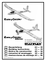 1
1
-
 2
2
-
 3
3
-
 4
4
-
 5
5
-
 6
6
-
 7
7
-
 8
8
-
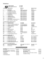 9
9
-
 10
10
-
 11
11
-
 12
12
-
 13
13
-
 14
14
-
 15
15
-
 16
16
-
 17
17
-
 18
18
-
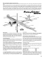 19
19
-
 20
20
-
 21
21
-
 22
22
-
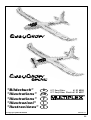 23
23
-
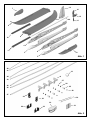 24
24
-
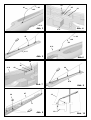 25
25
-
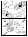 26
26
-
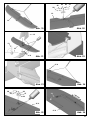 27
27
-
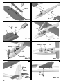 28
28
-
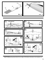 29
29
-
 30
30
-
 31
31
-
 32
32
-
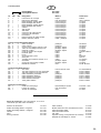 33
33
-
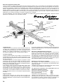 34
34
-
 35
35
-
 36
36
-
 37
37
-
 38
38
-
 39
39
-
 40
40
-
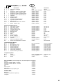 41
41
-
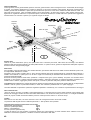 42
42
-
 43
43
-
 44
44
-
 45
45
-
 46
46
-
 47
47
-
 48
48
-
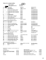 49
49
-
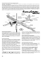 50
50
-
 51
51
-
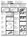 52
52


MULTIPLEX Easyglider Building Instructions
- Catégorie
- Jouets
- Taper
- Building Instructions
dans d''autres langues
- italiano: MULTIPLEX Easyglider
- English: MULTIPLEX Easyglider
- español: MULTIPLEX Easyglider
- Deutsch: MULTIPLEX Easyglider
Documents connexes
-
MULTIPLEX Easyglider Le manuel du propriétaire
-
MULTIPLEX Easyglider Pro 21 4226 Le manuel du propriétaire
-
-
HiTEC EasyStar Manuel utilisateur
-
-
-
-
-
-