Klein Tools CL440 Manuel utilisateur
- Catégorie
- Mesure, test
- Taper
- Manuel utilisateur
Ce manuel convient également à

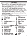
INSTRUCTION MANUAL
ENGLISH
FRANÇAIS pg. 37
ESPAÑOL pg. 19
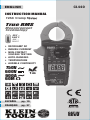
HVAC Clamp Meter
HVAC Clamp Meter
HVAC Clamp Meter
HVAC Clamp Meter
True RMS
Measurement
Technology
750V
600V
600A
60M
Ω
• MICROAMP DC
• INRUSH CURRENT
• NON-CONTACT
VOLTAGE TESTING
• AUTO-RANGING
• TEMPERATURE
• AUDIBLE CONTINUITY
5001748
1m
-328° –
2462°F
-200° –
1350°C
CL440
CAT IV
600V

2
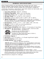
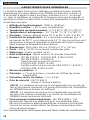
GENERAL SPECIFICATIONS
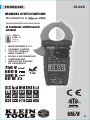
Klein Tools CL440 is an automatically ranging true root mean
square (TRMS) digital clamp meter that measures AC current and
inrush via the clamp, AC/DC voltage, DC microamps, resistance,
continuity, frequency, capacitance, and tests diodes via test-leads, and
temperature via a thermocouple probe.
• Operating Altitude: 6562 ft. (2000m)
• Relative Humidity: <95% non-condensing
• Operating Temp: 32° to 122°F (0° to 50°C)
• Storage Temp: 14° to 122°F (-10° to 50°C)
• Accuracy: Values stated at 65° to 83°F (18° to 28°C)
• Temp Coef cient: 0.1 × (Quoted Accuracy) per °C above
28°C or below 18°C, corrections are required when ambient
working temp is outside of Accuracy Temp range
• Dimensions: 10.04" × 3.77" × 1.57" (255 × 96 × 40 mm)
• Weight: 14.22 oz (403 g) including batteries
• Calibration: Accurate for one year
• Auto Power-Off (APO): After approx. 10 minutes of inactivity
• Standards: IEC EN 61010-1, 61010-2-032, 61010-2-033.
IEC EN 61326-1, 61326-2-2.
Conforms to UL STD.61010-1,
61010-2-032,61010-2-033;
Certified to CSA STD.C22.2 NO. 61010-1,
61010-2-032,61010-2-033.
• Pollution degree: 2
• Accuracy: ± (% of reading + # of least significant digits)
• Drop Protection: 3.3 ft. (1m)
• Safety Rating: CAT IV 600V
Class 2, Double insulation
CAT III: Measurement category III is applicable to test and
measuring circuits connected to the distribution part of the
building’s low-voltage MAINS installation.
CAT IV: Measurement category IV is applicable to test and
measuring circuits connected at the source of the building’s
low-voltage MAINS installation.
• Electromagnetic Environment: IEC EN 61326-1. This
equipment meets requirements for use in basic and controlled
electromagnetic environments like residential properties,
business premises, and light-industrial locations.
Specifications subject to change.
ENGLISH
5001748

3
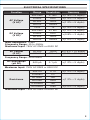
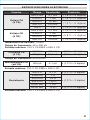
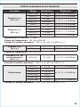
ELECTRICAL SPECIFICATIONS
Function Range Resolution Accuracy
AC Voltage
(V AC)
600.0mV 0.1mV
±(1.8% + 5 digits)
6.000V 1mV
±(1.5% + 5 digits)
60.00V 10mV
±(1.2% + 5 digits)
600.0V 100mV
750V 1V ±(1.5% + 5 digits)
DC Voltage
(V DC)
600.0mV 0.1mV ±(1.0% + 8 digits)
6.000V 1mV
±(0.8% + 3 digits)
60.00V 10mV
600.0V 100mV ±(1.0% + 3 digits)
Input Impedance: 10MΩ
Frequency Range: 45 to 400Hz
Maximum Input: 750V AC RMS or 600V DC
AC Current
(A AC)
60.00A 10mA ±(2.5% + 10 digits)
600.0A 100mA ±(2.0% + 10 digits)
Frequency Range: 50 to 60Hz
DC Microamps
(µA DC)
600 μA 0.1 μA ±(1.2% + 5 digits)
Maximum Input: 750V AC RMS or 600V DC
Resistance
600.0Ω 0.1Ω ±(1.2% + 5 digits)
6.000KΩ 1Ω
±(1.2% + 3 digits)
60.00kΩ 10Ω
600.0kΩ 100Ω
6.000MΩ 1kΩ
60.00MΩ 10kΩ ±(2.0% + 5 digits)
Maximum Input: 750V AC RMS or 600V DC

4
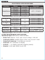
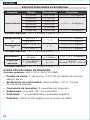
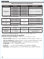
OTHER MEASUREMENT APPLICATIONS
Maximum Input: 600V DC or 750V AC RMS
• Diode Test: Approx. 1mA, open circuit voltage ~3.0V DC
• Continuity Check: Audible signal <10Ω, max current 1.5mA
• Sampling Frequency: 3 samples per second
• Overload: "OL" indicated on display
• Polarity: "-" on display indicates negative polarity
• Display: 3-5/6 digit, 6000 Count LCD
ELECTRICAL SPECIFICATIONS
Function Range Resolution Accuracy
Capacitance
60.00nF 0.010nF ±(4% + 25 digits)
600.0nF 0.100nF
±(4% + 8 digits)
6.000μF 0.001μF
60.00μF 0.010μF
600.0μF 0.100μF
6.000mF 0.001mF ±(5% + 9 digits)
Maximum Input: 750V AC RMS or 600V DC
Temperature
°F
-328° to 54°F
1
°F
±(1.5% + 7 digits)
55° to 2462°F
±(1.2% + 6 digits)
Temperature
°C
-200° to 12°C
1
°C
±(1.5% + 4 digits)
13° to 1350°C
±(1.2% + 3 digits)
Maximum Input: 750V AC RMS or 600V DC
Frequency
10Hz to
60kHz
0.001Hz
to 0.01kHz
±(0.1% + 5 digits)
Duty Cycle
0.1% to 99.9%
(≤10kHz)
0.1%
±1.5%
(Range: 10% – 90%)
Maximum Input: 750V AC RMS or 600V DC
ENGLISH

5
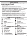
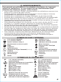
WARNINGS
To ensure safe operation and service of the meter, follow these instructions.
Failure to observe these warnings can result in severe injury or death.
• Before each use verify meter operation by measuring a known voltage
or current.
• Never use the meter on a circuit with voltages that exceed the category
based rating of this meter.
• Do not use the meter during electrical storms or in wet weather.
• Do not use the meter or test leads if they appear to be damaged.
• Use only with CAT III or CAT IV rated test leads.
• Ensure meter leads are fully seated, and keep fingers away from the
metal probe contacts when making measurements.
• Use caution when working with voltages above 25V AC RMS or 60V DC.
Such voltages pose a shock hazard.
• To avoid false readings that can lead to electrical shock, replace batteries
when a low battery indicator appears.
• Do not attempt to measure resistance or continuity on a live circuit.
• Always adhere to local and national safety codes. Use personal protective
equipment to prevent shock and arc blast injury where hazardous live
conductors are exposed.
• To avoid risk of electric shock, disconnect leads from any voltage source
before removing battery door.
• To avoid risk of electric shock, do not operate meter while battery door is removed.
SYMBOLS ON METER
AC (Alternating Current)
AC/DC Current
DC (Direct Current)
Resistance (in Ohms)
Double Insulated Class II
Audible Continuity
Warning or Caution
Ground
Diode
Risk of Electrical Shock
Hz
Frequency
Capacitance
%
Duty-cycle V Voltage (Volts)
°
F/
°
C
Temperature (Fahrenheit / Celsius) A Amperage (Amps)
COM Common NCV
Non-Contact Voltage Tester
% Duty cycle SEL Select
Backlight Hz Frequency
Positive Negative
SYMBOLS ON LCD
AC AC (Alternating Current) DC DC (Direct Current)
Negative Reading Data Hold
Auto Ranging MAX Maximum Value Hold
MIN Minimum Value Hold Audible Continuity
Low Battery
°
C
Degrees (Celsius)
°
F
Degrees (Fahrenheit)
k
kilo (value × 10
3
)
M
Mega (value × 10
6
)
μ
micro (value × 10
-6
)
m
milli (value × 10
-3
)
V
Volts (Voltage)
n
nano (value × 10
-9
) Ohms (Resistance)
A
Amps (Amperage)
F
Farads (Capacitance)
Hz%
Frequency/Duty Cycle Auto Power-Off
NCV
Non-Contact Voltage Tester Diode Test
Hazardous Voltage Indicator Inrush

6
ENGLISH
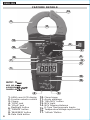
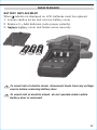
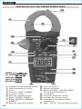
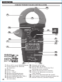
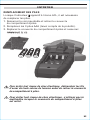
FEATURE DETAILS
NOTE: There
are no user-
serviceable parts
inside meter.
1.
6000 count LCD display
10.
Clamp trigger
2.
Function selector switch
11.
Arrow markings
3.
Clamp
12.
"SEL/NCV" button
4.
"COM" jack
13.
NCV Light
5.
"VΩµA" jack
14.
NCV Sensing Antenna
6.
Backlight button
15.
K-Type Thermocouple Inputs
7.
"RANGE" button
16.
Temperature/Voltage input switch
8.
"MAX/MIN" button
17.
"InRush" Button
9.
Data Hold button
NOTE: There
are no user-
serviceable parts
inside meter.
1
7
2
9
3
10
14
6
8
17
15
16
4 5
11
12
13

7
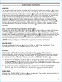
FUNCTION BUTTONS
ON/OFF
To power ON the meter, rotate the Function Selector switch
2
from
the OFF setting to any measurement setting. To power OFF the meter,
rotate the Function Selector switch
2
to the OFF setting. By default,
the meter will automatically power OFF after 10 minutes of inactivity.
If the meter automatically powers-OFF while in a measurement
setting, press any button to power the meter ON, or rotate Function
Selector
2
switch to OFF, then power ON the meter.
To deactivate
the power OFF functionality press and hold the "SELECT" button
12
before powering ON from the OFF setting. When auto power OFF
is deactivated, the Auto Power Off icon will not be visible in the
display.
SEL / NCV BUTTON (FOR NCV TESTING)
Press and hold the SEL/NCV button
12
to enter Non-contact Voltage
Testing (NCV) mode to test for presence of AC voltage. The NCV
icon and "EF" will be present on the display. Approach the conductor
under test leading with the sensing antenna
14
.
In the presence of AC
voltage, the red NCV light
13
will flash, audible signals (beeps) will
sound.
Release the SEL/NCV button to exit NCV testing mode.
NOTE: Only voltages of 40V AC or greater will be detected.
BACKLIGHT
Press Backlight button
6
to turn ON or OFF the backlight. The
backlight does not automatically power OFF.
RANGE
The meter defaults to auto-ranging mode . This mode
automatically determines the most appropriate measurement range
for the testing that is being conducted. To manually force the meter
to measure in a different range, use the "RANGE" button
7
.
1. Press the "RANGE" button
7
to manually select measurement
range ( is deactivated on the LCD). Repeatedly press the
"RANGE" button
7
to cycle through the available ranges, stopping
once the desired range is reached.
2. To return to auto-ranging mode, press and hold the "RANGE"
button
7
for more than two seconds ( is reactivated).
MAX/MIN
When the "MAX/MIN" button
8
is pressed, the meter keeps track of
the Maximum and Minimum values.

8
1. When measuring, press "MAX/MIN" button
8
to toggle between
the Maximum value (MAX), the Minimum value (MIN). If a new
maximum or minimum occurs, the display updates with that new
value.
2. Press "MAX/MIN" button
8
for more than two seconds to return
to normal measuring mode.
DATA HOLD
Press HOLD
9
to hold the measurement on the display. Press
HOLD
9
again to release the display to return to live measuring.
FUNCTION BUTTONS
ENGLISH

9
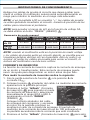
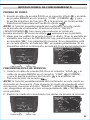
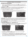
OPERATING INSTRUCTIONS
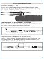
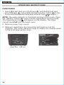
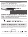
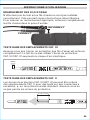
CONNECTING TEST LEADS
Do not test if leads are improperly seated. Results could cause
intermittent display readings. To ensure proper connection, firmly
press leads into the input jack completely.
TESTING IN CAT III MEASUREMENT LOCATIONS
Ensure the test lead shield is pressed firmly in place. Failure to use
the CATIII / CATIV shield increases arc-flash risk.
TESTING IN CAT II MEASUREMENT LOCATIONS
CAT III / CAT IV shields may be removed for CAT II locations. This
will allow testing on recessed conductors such as standard wall
outlets. Take care not to lose the shields.
5/32"
(4 mm)
.7" (18 mm)
INCORRECT
CORRECT

10
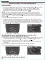
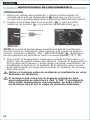
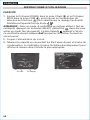
OPERATING INSTRUCTIONS
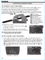
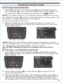
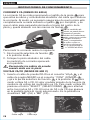
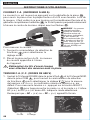
AC CURRENT (LESS THAN 600A)
AC Current is measured by pressing the clamp trigger
10
to open
the clamp and placing it around a current-carrying wire. When
measuring, care should be taken to ensure that the clamp is
completely closed with trigger
10
fully released, and that the wire
passes perpendicularly through the center of the clamp in line with
the arrow markings
11
.
To measure current:
1. Rotate the Function Selector switch
2
to the A~ setting.
2. Place clamp around wire. The current
measurement will be shown in the display.
Disconnect test leads when
measuring with the clamp.
ENGLISH
Red leadBlack lead
NOTE: Current
measurement can be
made by clamping
around single
conductors, but not
cables containing
both live and neutral
wires. In this case a
line splitter is required,
Klein Cat. No. 69409 is
recommended.
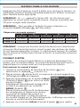
AC/DC VOLTAGE (LESS THAN 600V)
1. Insert RED test lead into VΩµA jack
5
, and BLACK test lead
into COM jack
4
, and rotate function selector switch
2
to the
V
setting for AC or DC measurements. The meter defaults to
AC measurement. To measure DC, press the "SELECT" button
12
to toggle between AC and DC modes. The AC or DC icon on
the LCD indicates which mode is selected. Note "AC" or "DC" on
the display.
the arrow markings
11
11
.
WIREWIRE
NOTE:
measurement can be
made by clamping
around single
conductors, but not
cables containing
both live and neutral
wires. In this case a
line splitter is required,
Klein Cat. No. 69409 is

11
OPERATING INSTRUCTIONS
Apply test leads to the circuit to be tested to measure voltage.
The meter will auto-range to display the measurement in the most
appropriate range.
NOTE: If "–" appears on the LCD, the test leads are being applied to
the circuit in reverse. Swap the position of the leads to correct this.
NOTE: To access mV range for V AC , the 'RANGE' button
7
must
be used.
NOTE: When in a voltage setting and the test leads are open,
readings of order mV may appear on the display. This is noise and
is normal. By touching the test leads together to close the circuit
the meter will measure zero volts.
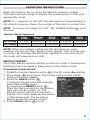
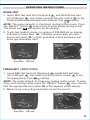
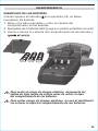
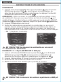
INRUSH CURRENT
The Inrush feature captures starting current of a motor or transformer.
Starting current can assist in diagnosing a motor before it fails.
To measure inrush current:
1. Rotate the Function Selector switch
2
to the AC current A setting.
2. Place clamp
3
around wire. The current measurement will be
shown in the main display.
3. Press the InRush button
17
to enter the Inrush mode and manually
select 60A or 600A range
by pressing the RANGE button
7
.
Place the clamp around the compressor
start wire and turn motor on. The
starting current will hold on the main
display. The Inrush measurement period
is 100-miliseconds. The secondary
display measures running current.
4. Press InRush button
17
to exit.
Manual Mode Sequence
First
Press
Second
Press
Third
Press
Fourth
Press
Fifth
Press
AC Range 0-750V 0-600.0V 0-60.00V 0-6.000V
0-600.0mV
DC Range 0-60.00V 0-6.000V
0-600.0mV
0-600.0V 0-60.00V

12
ENGLISH
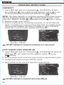
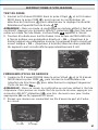
CONTINUITY
1. Insert RED test lead into VΩµA jack
5
, and BLACK test lead
into COM jack
4
, and rotate function selector switch
2
to the
Continuity/Resistance/Capacitance/Diode-Test
setting.
NOTE: The meter defaults to Continuity testing in this mode. Ensure
that the Continuity Testing icon is visible on the display. If not,
press the "SELECT" button
12
repeatedly until the icon is shown.
2. Remove power from circuit.
3. Test for continuity by connecting conductor or circuit with test
leads. If resistance is measured less than 10Ω, an audible signal
will sound and display will show a resistance value indicating
continuity. If circuit is open display will show "OL".
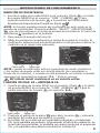
µA DC CURENT (LESS THAN 600 µA)
1. Insert RED test lead into VΩµA jack
5
, and BLACK test lead into
COM jack
4
, and rotate function selector switch
2
to the
µA
setting.
2. Remove power from circuit and open circuit at measurement point.
3. Connect test leads in series with the circuit.
4. Apply power to the circuit to take the measurement.
DO NOT attempt to measure continuity on a live circuit.
OPERATING INSTRUCTIONS
DO NOT attempt to measure more than 600 µA.
Red leadBlack lead
Red leadBlack lead

13
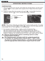
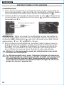
AC VOLTAGE
+
AC AMPERAGE FUNCTION
1. Insert RED test lead into VΩµA jack
5
, and BLACK test lead
into COM jack
4
, and rotate function selector switch
2
to the
V+A~ setting.
2. Press clamp trigger
13
to open clamp
3
and place around
current-carrying wire.
3. The main display will show AC Voltage and the secondary
display will show AC Amperage. Pressing the select button
will reverse the displays; the main display will show AC
Amperage and the secondary display will show AC Voltage.
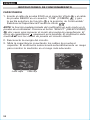
OPERATING INSTRUCTIONS
RESISTANCE MEASUREMENTS
1. Insert RED test lead into VΩµA jack
5
, and BLACK test lead
into COM jack
4
, and rotate function selector switch
2
to the
Continuity/Resistance/Capacitance/Diode-Test
setting.
NOTE: The meter defaults to Continuity testing in this mode. Press
the "SELECT" button
12
once to enter Resistance testing mode. The
Resistance icon
will appear on the display.
2. Remove power from circuit.
3. Measure resistance by connecting test leads to circuit. The
meter will auto-range to display the measurement in the most
appropriate range.
NOTE: When in a Resistance setting and the test leads are open
(not connected across a resistor), or when a failed resistor is under
test, the display will indicate "O.L." This is normal.
DO NOT attempt to measure resistance on a live circuit.
Red leadBlack lead
Red leadBlack lead

14
ENGLISH
CAPACITANCE
1. Insert RED test lead into VΩµA jack
5
, and BLACK test lead
into COM jack
4
, and rotate function selector switch
2
to the
Continuity/Resistance/Capacitance/Diode-Test
setting.
NOTE: The meter defaults to Continuity testing in this mode. Press
the "SELECT" button
12
twice to enter Capacitance testing mode.
The Capacitance icon
will appear on the display. The meter
should read 0 nF with test leads open.
2. Remove power from circuit.
3. Measure capacitance by connecting test leads across the
capacitor. The meter will auto-range to display the measurement
in the most appropriate range.
OPERATING INSTRUCTIONS
Red leadBlack lead

15
OPERATING INSTRUCTIONS
DIODE TEST
1. Insert RED test lead into VΩµA jack
5
, and BLACK test lead
into COM jack
4
, and rotate function selector switch
2
to the
Continuity/Resistance/Capacitance/Diode-Test
setting.
NOTE: The meter defaults to Continuity testing in this mode. Press
the "SELECT" button
12
three times to enter Diode testing mode.
The Diode icon
will appear on the display.
2. Touch test leads to diode. A reading of 200-800mV on display
indicates forward bias, "OL" indicates reverse bias. An open
device will show "OL" in both polarities. A shorted device will
show approximately 0mV.
FREQUENCY / DUTY-CYCLE
1. Insert RED test lead into VΩµA jack
5
and BLACK test lead
into COM jack
4
, and rotate function selector switch
2
to the
Frequency/Duty-Cycle
setting.
NOTE: The meter defaults to Frequency testing in this mode. To enter
Duty-Cycle testing mode, press the "SELECT" button
12
once. Ensure
that the appropriate icon (either
Hz
or
%
) appears on the display.
2. Measure by connecting test leads across the circuit.
Red leadBlack lead
Red leadBlack lead

16
ENGLISH
OPERATING INSTRUCTIONS
TEMPERATURE
1. Remove leads from meter and slide the temperature probe input
switch
18
to close jacks and expose the K-Type thermocouple
ports.
2. Insert K-type thermocouple into port
15
( and rotate function
selector switch
2
to the Temperature setting.
NOTE: The meter defaults to Fahrenheit scale in this mode. To enter
Celsius scale, press the SEL button
9
. Ensure that the appropriate
icon (either
°F
or
°C
) appears on the display.
3. To measure temperature, make contact between the
thermocouple tip and the object being measured. When
thermocouple tip and object are in thermal equilibrium, the
measurement on the display will stabilize. The meter will auto-
range to display the measurement in the most appropriate range.
Remove thermocouple before switching meter to other
measurement functions.
T
he thermocouple included with the original purchase
is suitable for temperatures below 356°F / 180°C only.
To measure higher temperatures, a K-type thermocouple
with the appropriate measurement range should be used.
K-Type Thermocouple

17
MAINTENANCE
BATTERY REPLACEMENT
When indicator is displayed on LCD, batteries must be replaced.
1. Loosen captive screw and remove battery cover.
2. Replace 3 × AAA batteries (note proper polarity).
3. Replace battery cover and fasten screw securely.
T
o avoid risk of electric shock, disconnect leads from any voltage
source before removing battery door.
To avoid risk of electric shock, do not operate meter while
battery door is removed.
Replace battery cover and fasten screw securely.

18
ENGLISH
CLEANING
Be sure meter is turned off and wipe with a clean, dry lint-free
cloth.
Do not use abrasive cleaners or solvents.
STORAGE
Remove the batteries when meter is not in use for a prolonged
period of time. Do not expose to high temperatures or
humidity. After a period of storage in extreme conditions
exceeding the limits mentioned in the General Specifications
section, allow the meter to return to normal operating
conditions before using.
WARRANTY
www.kleintools.com/warranty
DISPOSAL / RECYCLE
Do not place equipment and its accessories in the trash.
Items must be properly disposed of in accordance with
local regulations. Please see www.epa.gov or www.
erecycle.org for additional information.
CUSTOMER SERVICE
KLEINTOOLS, INC.
450Bond Street
Lincolnshire, IL60069
1-800-553-4676
www.kleintools.com

19
5001748
CL440
CAT IV
600 V
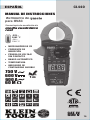
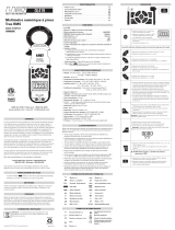
MANUAL DE INSTRUCCIONES
Multímetro de gancho
Multímetro de gancho
Multímetro de gancho
Multímetro de gancho
para HVAC
Tecnología de medición de
media cuadrática
real
750 V
600 V
600 A
60 M
Ω
• MICROAMPERIOS CD
• CORRIENTE DE
INSERCIÓN
• PRUEBA DE VOLTAJE
SINCONTACTO
• RANGO AUTOMÁTICO
• TEMPERATURA
• INDICADOR DE
CONTINUIDAD AUDIBLE
-328 –
2462°F
-200 –
1350°C
ESPAÑOL
1m

20
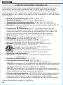
ESPECIFICACIONES GENERALES
El CL440 de Klein Tools es un multímetro digital de gancho de rango
automático con media cuadrática real (TRMS) que mide corriente
CA y corriente de inserción con la pinza, así como el voltaje CA/CD,
microamperios CD, resistencia, continuidad, frecuencia y capacitancia,
prueba diodos con cables de prueba y mide temperatura con una sonda
de termopar.
• Altitud de funcionamiento: 6562' (2000m)
• Humedad relativa: <95%, sin condensación
• Temperatura de funcionamiento: 32 a 122°F (0 a 50°C)
• Temperatura de almacenamiento: 14 a 122°F (-10 a 50°C)
• Precisión: valores establecidos a una temperatura de 65 a 83°F
(18 a 28°C)
• Coe ciente de temperatura: 0,1 × (precisión indicada) por
cada °C por encima de los 28°C o por debajo de los 18°C; es
necesario realizar correcciones si la temperatura de trabajo se
encuentra fuera del rango de la temperatura de precisión
• Dimensiones: 10,04"×3,77"×1,57"(255×96×40mm)
• Peso: 14,22oz (403g) incluidas las baterías
• Calibración: precisa durante un año
• Función de apagado automático (APO): después de
aproximadamente 10minutos de inactividad
• Normas: IECEN61010-1, 61010-2-032, 61010-2-033.
IECEN61326-1, 61326-2-2.
Cumple con las normas UL STD.61010-1,
61010-2-032, 61010-2-033;
Certificado según las normas CSA STD.C22.2
n.º 61010-1, 61010-2-032, 61010-2-033.
• Grado de contaminación: 2
• Precisión: ± (% de lectura + cantidad de dígitos menos
significativos)
• Protección ante caídas: 3,3'(1m)
• Clasi cación de seguridad: CATIV 600V
Clase2, doble aislamiento
CATIII: la categoría III de medición es aplicable a los circuitos de
medición y prueba conectados a la distribución de la instalación
de redes eléctricas de bajo voltaje de un edificio.
CATIV: la categoría IV de medición es aplicable a los circuitos
de medición y prueba conectados a la fuente de la instalación de
redes eléctricas de bajo voltaje de un edificio.
• Entorno electromagnético: IEC EN 61326-1. Este equipo cumple
con los requisitos para su uso en entornos electromagnéticos
básicos y controlados, como propiedades residenciales,
establecimientos comerciales e instalaciones de industria ligera.
Especificaciones sujetas a cambios.
ESPAÑOL
5001748
La page est en cours de chargement...
La page est en cours de chargement...
La page est en cours de chargement...
La page est en cours de chargement...
La page est en cours de chargement...
La page est en cours de chargement...
La page est en cours de chargement...
La page est en cours de chargement...
La page est en cours de chargement...
La page est en cours de chargement...
La page est en cours de chargement...
La page est en cours de chargement...
La page est en cours de chargement...
La page est en cours de chargement...
La page est en cours de chargement...
La page est en cours de chargement...
La page est en cours de chargement...
La page est en cours de chargement...
La page est en cours de chargement...
La page est en cours de chargement...
La page est en cours de chargement...
La page est en cours de chargement...
La page est en cours de chargement...
La page est en cours de chargement...
La page est en cours de chargement...
La page est en cours de chargement...
La page est en cours de chargement...
La page est en cours de chargement...
La page est en cours de chargement...
La page est en cours de chargement...
La page est en cours de chargement...
La page est en cours de chargement...
La page est en cours de chargement...
La page est en cours de chargement...
La page est en cours de chargement...
La page est en cours de chargement...
-
 1
1
-
 2
2
-
 3
3
-
 4
4
-
 5
5
-
 6
6
-
 7
7
-
 8
8
-
 9
9
-
 10
10
-
 11
11
-
 12
12
-
 13
13
-
 14
14
-
 15
15
-
 16
16
-
 17
17
-
 18
18
-
 19
19
-
 20
20
-
 21
21
-
 22
22
-
 23
23
-
 24
24
-
 25
25
-
 26
26
-
 27
27
-
 28
28
-
 29
29
-
 30
30
-
 31
31
-
 32
32
-
 33
33
-
 34
34
-
 35
35
-
 36
36
-
 37
37
-
 38
38
-
 39
39
-
 40
40
-
 41
41
-
 42
42
-
 43
43
-
 44
44
-
 45
45
-
 46
46
-
 47
47
-
 48
48
-
 49
49
-
 50
50
-
 51
51
-
 52
52
-
 53
53
-
 54
54
-
 55
55
-
 56
56


Klein Tools CL440 Manuel utilisateur
- Catégorie
- Mesure, test
- Taper
- Manuel utilisateur
- Ce manuel convient également à
dans d''autres langues
- English: Klein Tools CL440 User manual
- español: Klein Tools CL440 Manual de usuario
Documents connexes
-
Klein Tools CL445 Manuel utilisateur
-
-
Klein Tools CL220 Manuel utilisateur
-
-
Klein Tools CL120KIT Mode d'emploi
-
-
-
-
-
Autres documents
-
General DAMP68 Manuel utilisateur
-
Amprobe AM-560 & AM-570 Mutimeter Manuel utilisateur
-
Metrix MX 350 Manuel utilisateur
-
UEi DL379 Le manuel du propriétaire
-
Ideal 61-405 Manuel utilisateur
-
 UEi DL419 Le manuel du propriétaire
-
-
-
-
