Honeywell Commercial Touchscreen Thermostat Manuel utilisateur
- Catégorie
- Thermostats
- Taper
- Manuel utilisateur

PRODUCT DATA
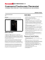
Commercial Touchscreen Thermostat
CONNECTED DEVICE FOR COMMERCIAL BUILDINGS
Trademark Information
TBD
Disclaimer
All images used in this document are for illustrative
purposes only and may not match the actual product.
APPLICATION
TC500A-N/TC500B-NThermostat is an advanced,
configurable, connected device for commercial buildings.
It controls and monitors RTU, AHU, Heat Pump equipment,
and their configurations. This device communicates over
Wi-Fi, Bluetooth, BACnet IP, Sylk, easily integrates with the
building automation system.
The built-in intelligent control algorithms of the device
help to achieve the perfect balance between Energy
Efficiency and Comfort. The device is packaged with
numerous presets suitable for most commercial building
requirements that enable the easy and quick initial setup.
The firmware of the device can be upgraded via Wi-Fi
network. The device has four universal terminals and a
pair of Sylk terminals to connect with sensors or other
accessories. It also has a built-in temperature sensor,
humidity sensor, and proximity sensor.
FEATURES
• The device can be easily commissioned through Deploy
app after connected to Gateway.
• Easily customizable and intuitive UI.
• Supports BACnet system schedule and holiday
configuration.
• Multiple, configurable, levels of user privilege access
for features such as Reminders, Occupancy set points,
Date/Time, Schedules, Calendars of special events,
remote and local Manual Override, remote and local
Occupancy Override, Choice of language and units, and
so on.
• Multiple, configurable, screen lockouts to prevent
unauthorized settings changes.
• High level control algorithms such as Auto Changeover,
Adaptive Intelligent Recovery, Pre-occupancy Purge,
Power up disable time, Freeze protection, and Demand
limit controls are supported.
• Settings to switch Fahrenheit to Celsius and vice-versa.
• Auto display sleep to save energy when there is no user
action for configured time out.
• A LED indicator to show the operational status of the
thermostat when the display goes to sleep mode.
• Real-Time Clock time keeping accuracy with 72 hour
retention during power loss.
Equipment Control Features
• 4H/3C Heat Pump, 3H/3C Conventional and
modulating heat system
• Constant speed Fan, 2-speed Fan, and Variable Speed
Fan
• Packaged Economizer Coordination Output
• Multiple Dehumidification and Humidification options
• Service mode to manually command the outputs to test
the operation of the mechanical equipment
• Auto mode to switch between heating and cooling
according to the current space temperature
• Staging control, PID Tuning, CPH, OAT Lockout, DAT
Lockout, Modulating control
• Demand Limit Control to save energy
• System Switch Options
• Smoke Monitor

COMMERCIAL TOUCHSCREEN THERMOSTAT
EN0B-0206 IE10 R0720 2
TECHNICAL SPECIFICATIONS
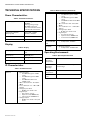
Power Characteristics
Display
IO Characteristics
Operating Environment
Table 1. Power Characteristics
Power Supply Rated voltage: 24VAC
50/60Hz,
Working voltage range:
20-30VAC, UL listed
class-2 transformer or IEC
61558 listed transformer.
Power Consumption
(Display ON)
Max. 8.5VA @ 24VAC
(355mA @ 24VAC)
Min. Load 8VA (all BOs OFF)
Max. Load 96VA (all BOs ON)
Table 2. Display
Display Type 24 BPP TFT display with
CTP
Resolutions 480x480 pixel
Active Display Area 4” diagonally
Backlight LCD (Dimmable)
Table 3. IO Characteristics
UIO x 2 • Resistive Input
— For 10K NTC type II, C7021
series
— For 10K NTC type III,C7023
series
— For 20K NTC, TR21 and
C7041 series.
• ±0.5°C (±1°F) at 10 – 32°C (50 –
90°F)
• ±1.1°C (±2°F) at -1.1 – 50°C (30 –
122°F)
• Voltage Input, SELV
— 0-10V, ±5% of full scale
• Digital Input
— Dry contact closure
— Open circuit (≥ 100Kohms)
— Closed circuit (≤100ohms)
• Voltage Output
— 0-10V, ±3% of full scale @2K
ohms
UI x 2 • Resistive Input
— for 10K NTC type II, C7021
series
— for 10K NTC type III,C7023
series
— for 20K NTC, TR21 and C7041
series
• ±0.5°C (±1°F) at 10 – 32°C (50 –
90°F)
• ±1.1°C (±2°F) at -1.1 – 50°C (30 –
122°F)
• Voltage Input, SELV
— 0-10V, ±5% of full scale
• Digital Input
— Dry contact closure
— Open circuit (≥ 100Kohms)
— Closed circuit (≤100ohms)
DO (G,
Y1,Y2,Y3,W1,W2
,W3)
• Relay Output
— 1 Amps Max. at 24VAC
DO (AUX) • Relay Dry Contact
— 1 Amps Max. at 24VAC/DC
Table 4. Operating Environment
Ambient
Operating
Temperature
32 to 122 °F (0 to +50°C)
Ambient
Operating
Humidity
10 to 90% relative humidity (non-
condensing)
Storage
Temperature
-40 to 150 °F(-40 to 65.5°C)
Protection
Class
IP20
Table 3. IO Characteristics (Continued)

COMMERCIAL TOUCHSCREEN THERMOSTAT
3 EN0B-0206 IE10 R0720
Compliances
Communication Baud Rates
Electrical Characteristics
Supported Sensors and Devices
• Indoor/Outdoor Air Temp Sensor
• Discharge sensor/Supply air sensor
• CO2 sensor
• Mixed air sensor
• Occupancy sensor
• Dirty filter
• Proof of airflow
• Proof of waterflow
• Sylk Sensor Bus devices (TR40 series and C7400S)
• Up to four TR40 series room sensors
• Up to two C7400S duct sensors
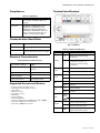
Terminal Identification
Fig. 1. Terminals
Table 5. Compliances
Certificates CE, FCC, ICES, UL/cUL, RoHs, REACH,
Title 24, BTL, ASHRAE, LEED, and
Prop65.
Standards EN 60730-1, EN 60730-2-9, EN
301489-1, EN 301489-17, EN
300328, EN 301893, EN 62479,
UL60730-1, UL60730-2-9, Title 47
part 15 subpart B, Title 47 part 15
subpart C, RSS 210, ICES-003
BACnet IP Over Wi-Fi
Wi-Fi 802.11 b/g/n
Bluetooth BLE 4.2 with 1 Mbps
Classic Bluetooth with max. 3 Mbps
Table 6. Electrical Characteristics
Rated Impulse Voltage 500 V
Construction of Control Independently Mounted
Control
Operation Method Type 1 Action
Pollution Degree 2
Purpose of Control Operating Control
Table 7. Terminal identification
Terminal Label Connection
24VAC
R24VAC power from heating
transformer
C
24VAC common (Neutral). For 2
transformer systems, use
common wire from cooling
transformer
UIO1
1 Universal input/output
COM Common
UIO2
2 Universal input/output
COM Common
UI1
1 Universal input
COM Common
UI2
2 Universal input
COM Common
Sylk
Sylk bus, master, power output
Sylk bus, master, power output
RS485
+ BACnet Communications
_ BACnet Communications
R-RC Jumper between R and RC for
single transformer system

COMMERCIAL TOUCHSCREEN THERMOSTAT
EN0B-0206 IE10 R0720 4
Thermostat Ordering Part Numbers
24VAC
RC 24VAC power from cooling
transformer
G Fan
Y1 Relay output, Compressor
contactor (stage1)
Y2 Relay output, Compressor
contactor (stage2)
Y3
Relay output, Compressor
contactor (stage3)/Configurable
Output
W1 Relay output, Heat (stage1)
W2 Relay output, Heat (stage2)
W3 Relay output, heat
(stage3)/Configurable Output
Aux
Relay dry contact, Aux-1
Relay dry contact, Aux-2
Table 7. Terminal identification
Terminal Label Connection Table 8. Thermostat Part Numbers
TC500A-N/TC500B-N Thermostat with North
American conformance

COMMERCIAL TOUCHSCREEN THERMOSTAT
5 EN0B-0206 IE10 R0720
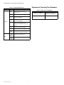
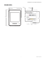
DIMENSIONS
3 -19/32 ” (91.2 mm)
4 - 15/32”
(113.7 mm)
4 x 11/32”
(9mm)
2 - 3/8”
(60.3mm)
3 - 1/4”
(82.75mm)
4 x 3/16”
(4.5mm)

COMMERCIAL TOUCHSCREEN THERMOSTAT
Honeywell Building Solutions
Honeywell International Inc.
1985 Douglas Drive North
Golden Valley, MN 55422
customer.honeywell.com
® U.S. Registered Trademark
© 2020 Honeywell International Inc.
EN0B-0206 IE10 R0720
GENERAL SAFETY
INFORMATION
• When performing any work (installation, mounting,
start-up), all manufacturer instructions and in
particular the Installation and Commissioning
Instructions (MU1B-0208IE10) are to be observed.
• TC500A-N/TC500B-N Thermostat may be installed
and mounted only by authorized and trained personnel.
•Rules regarding electrostatic discharge should be
followed.
•TC500A-N/TC500B-N Thermostat is modified in any
way, except by the manufacturer, all warranties
concerning operation and safety are invalidated.
•Make sure that the local standards and regulations are
observed at all times.
•Use only accessory equipment which comes from or
has been approved by Honeywell.
•It is recommended that devices be kept at room
temperature for at least 24 hours before applying
power. This is to allow any condensation resulting from
low shipping/storage temperatures to evaporate.
•Investigated according to United States Standard UL-
60730-1, and UL60730-2-9.
•Investigated according to Canadian National
Standard(s) C22.2, No. 205-M1983 (CNL-listed).
•Do not open TC500A-N/TC500B-N Thermostat, as it
contains no user-serviceable parts inside!
•CE declarations according to LVD Directive
2014/35/EU and EMC Directive 2014/30/EU.
•Product standards are EN 60730-1 and EN 60730-2-9.
• TC500A-N/TC500B-N Thermostat is Class B digital
apparatus and complies with Canadian ICES-003.
• This device complies with part 15 of the FCC Rules.
Operation is subject to the following two conditions: (1)
This device may not cause harmful interference, and (2)
this device must accept any interference received,
including interference that may cause undesired
operation.
• Caution: Changes or modifications to this unit not
expressly approved by the party responsible for
compliance could void the user's authority to operate
the equipment.
• This device contains licence-exempt
transmitter(s)/receiver(s) that comply with Innovation,
Science and Economic Development Canada’s licence-
exempt RSS(s). Operation is subject to the following
two conditions:
1. This device may not cause interference.
2. This device must accept any interference, including
interference that may cause undesired operation of
the device.
• L’émetteur/récepteur exempt de licence contenu dans
le présent appareil est conforme aux CNR d’Innovation,
Sciences et Développement économique Canada
applicables aux appareils radio exempts de licence.
L’exploitation est autorisée aux deux conditions
suivantes:
1. L’appareil ne doit pas produire de brouillage;
2. L’appareil doit accepter tout brouillage radioélec-
trique subi, même si le brouillage est susceptible
d’en compromettre le fonctionnement.
•This equipment has been tested and found to comply
with the limits for a Class B digital device, pursuant to
part 15 of the FCC Rules. These limits are designed to
provide reasonable protection against harmful
interference in a residential installation. This
equipment generates uses and can radiate radio
frequency energy and, if not installed and used in
accordance with the instructions, may cause harmful
interference to radio communications. However, there
is no guarantee that interference will not occur in a
particular installation. If this equipment does cause
harmful interference to radio or television reception,
which can be determined by turning the equipment off
and on, the user is encouraged to try to correct the
interference by one or more of the following measures:
— Reorient or relocate the receiving antenna.
— Increase the separation between the equipment
and receiver.
— Connect the equipment into an outlet on a circuit
different from that to which the receiver is con-
nected.
— Consult the dealer or an experienced radio/TV
technician for help.
• To satisfy FCC&IC RF exposure requirements, a
separation distance of 20 cm or more should be
maintained between the antenna of this device and
persons during device operation. To ensure
compliance, operations at closer than this distance is
not recommended.
• Les antennes installées doivent être situées de facon à
ce que la population ne puisse y être exposée à une
distance de moin de 20 cm. Installer les antennes de
facon à ce que le personnel ne puisse approcher à 20
cm ou moins de la position centrale de l’ antenne.
Region Selection (for Wi-Fi 2.4G device)
• Limited by local law regulations, version for North
America does not have region selection option.
Safety Information as per EN60730-1
TC500A-N/TC500B-N Thermostat is intended for
residential, commercial environments.
TC500A-N/TC500B-N Thermostat is an independently
mounted electronic control system with fixed wiring.
TC500A-N/TC500B-N Thermostat is used for the purpose
of building HVAC control and is suitable for use only in
non-safety controls for installation on or in appliances.
-
 1
1
-
 2
2
-
 3
3
-
 4
4
-
 5
5
-
 6
6


Honeywell Commercial Touchscreen Thermostat Manuel utilisateur
- Catégorie
- Thermostats
- Taper
- Manuel utilisateur
dans d''autres langues
Documents connexes
Autres documents
-
SBC PCD7.LRxx BACnet Room Controller Mode d'emploi
-
-
-
Johnson Controls FMS-2000C Guide d'installation
-
SBC PCD7.LR-TR40 and PCD7.LR-TR42 LCD and non-LCD Wall Modules Fiche technique
-
wattstopper LMRC-111-16M Mode d'emploi
-
-
Danfoss ERC 214 Digital controller for refrigeration and defrost, 4 relay Guide d'installation
-
STEINEL DCS CONNECT Manuel utilisateur