
EMPAVA APPLIANCE INC.
Add: 15253 Don Julian Rd, City of Industry, CA 91745
Tel: 888-682-8882
www.empava.com
RANGE HOOD
Installation and Operation
Manual

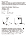
TECHNICAL CHARACTERISTICS
Dear consumer,
Thanks for your purchase of our range hood and we hope we can fully
satisfy all of your needs. Please read the entire instructions carefully
before proceeding to obtain the best results of operation the range hood.
Please note that this product is marked with symbol:
According to Waste of Electrical Electron Equipment
(WEEE) directive, WEEE should be separately collected
and treated. If at any time in future you need to dispose of
this product, please do NOT dispose of this product with
household waste. Please send this product to WEEE
collecting points where available.
Model No.: EMPV-30RH05 EMPV-30RH06
Total power: 204W
Motor power: 200W
Led Light: 2x2W
Voltage: 120V
Frequency: 60Hz
Filter: Steel Baffle filter
Control: Touch Control
25.98"-37.6"
9.
06"
7
.
4
6"
10.43"
2"
18.9"
29.5"
/35
.
23
"
EMPV-30RH05 EMPV-30RH06
34.94"-36.61"
3"
18
.
9
"
2
9
.
5
"
/
3
5.2
3"
1
1.
8
1"
11
.
26"

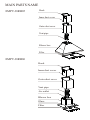
MAIN PARTS NAME
Hook
Inner duct cover
Outer duct cover
Vent pipe
Blower box
Filter
Hook
Inner duct cover
Outer duct cover
Vent pipe
Blower box
Air outlet
Glass
Filter
EMPV-30RH05
EMPV-30RH06

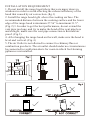
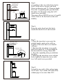
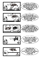
INSTALLATION REQUIREMENT
1. Do not install the range hood where there are many doors ro
windows in order to avoid effecting the exhaust efficiency of the
hood that caused by air convection. (fig.1)
2. Install the range hood right above the cooking surface. The
recommended distance between the cooking surface and the lower
edge of the range hood is minimum 27.56" to maximum 31.5".
(Fig.2) 3. In order to get the best performance, do not extend the
vent pipe too long, and try to make the bend of the vent pipe less
and straight, make sure the vent pipe connection is firm and air
proof. (Fig.3)
4. After hanging the range hood on the wall, make sure the hood is
level and vertical. (Fig.4)
5. The air Outlet is not allowed to connect to chimney flues or
combustion gas ducts. The air outlet should under no circumstances
be connected to ventilation ducts for room in which fuel-burning
ppliances are installed.

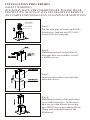
INSTA L L AT I O N P R O C E D U R E S
SAFETY WARNING
HOOD MAY HAVE VERY SHARP EDGES; PLEASE WEAR
PROTECTIVE GLOVES IF IT IS NECESSARY TO REMOVE
ANY PARTS FOR INSTALLING, CLEANING OR SERVICING.
Vent pipe
Air outlet
Step 1:
Put the vent pipe to the air outlet like
this picture. And use one ST3.9x10
screw to fix the vent pipe.
Step 2:
Matching the hook to the holes of
the inner duct cover and fix it well
with M4 screws.
Step 3:
Insert the inner duct cover into the
outer duct cover.
Step 4:
Matching the holes of the outer duct
cover and blower box, fix the outer
duct cover to the blower box using
8pcs M4*10 screw provided with the
fixing tool as the direction of the
illustrated.

5x50
Metal Screw
Expanding Tube
5x50
Wood Screw
Expanding Tube
Metal Screw
5x50
Expanding tube
Hook
A
B
200
367
C
Step 6:
Hang the entire hood onto the hook,
ensure the hood is level and vertical.
Step 7:
1. Draw the inner duct cover up to the
suitable height, mark on the wall two
keyhole of the outer duct cover bracket
with pen .
2. Put down the inner duct cover gently,
drill the keyholes in 75-85 mm depth on
the horizontal level using 10mm drill.
3. Press the expanding tube provided into
the holes.
4. Matching the inner duct cover with the
holes, tighten the inner duct cover with
two 5x50 metal screw provided.
Step 8:
Extend the air outlet of the exhaust pipe
out-of-door. Try to make the bend of the
exhaust pipe is no more than 120°.
Step5:
A ccording to the size of hook key holes.
10mm in diameter and 75~85mm in depth.
Press the 3 expanding tube provided into
the holes. Fix the hook using the 5x50
metal screw provided.
Then insert three M5X50 screws to A and B
And C holes to fix the hook on the wall
Drill 3 holes in level in the wall with
steadily.

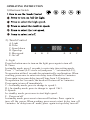
OPERATING INSTRUCTION
1).Electronic Switch
A. Light
B. Time
C. Speed down
D. Speed up
E. Max speed
F. On /off
A B C D E F
2). Touch Control
A: Light
Press the button once to turn on the light, press again to turn off.
B. Timer
In standby mode, press 3 seconds, to enter into time setting mode,
Press “+” set hour (0-23 circle set) and press “–” set minute(0-59),
No operation within 5 seconds for automatically confirmation. When
working, press once to enter into delay turn off mode for 3 minutes.
Press again to increase delay turn off time from 3-59 minutes.
No operation for 5 seconds, the hood will be turn off in 3 minutes.
Press again to turn off immediately.
C.- In standby mode, press to change to speed 1.
D.+ In standby mode, press to change to speed 2 & 3.
E. Speeds
In standby mode, press once to start high speed.
F. Power on/off
In standby mode, press once to turn on all buttons. Press again to
turn off the power. When working, press once to start delay turn off
3 minutes. In delay turn off mode, press again to stop delay turn off.

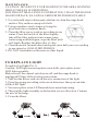
MA I N TE N A NC E
CAUTION: NEVER PUT YOUR HAND INTO THE AREA HOUSING
WHILE THE FAN IS OPERATING.
FOR THE OPTIMAL LEVEL FO OPERATION, CLEAN THE RANGE
HOOD SURFACE, AN AND ALUMINUM FILTER REGULARLY.
1. Use only mild soap or detergent solutions to clean the range hood
surface. Dry surfaces using soft cloth.
2. Using a stainless steel cleaner to bring the
glow back into a stainless finish.
3. Clean the filter once a week or according to use
status. Press the buckle of the filter slightly,
take off the filter and put it into warm soapy
water using mild detergent, wipe the filter with
soft brush. Replace the filter after it’s dry.
4. Clean the motor fan and other inside parts once half year or according
to use status by QUALIFIED PERSON.
5. DO NOT clean motor with water or other liquid.
To replace Led light (Pic.1)
Сaution: LED light can not replace a new bulb, just replace a new
LED light assembly.
Make sure all the control switches are off, and the range hood is
unplugged! Please follow below instructions:
1. Take out the filters, and cut off the wire connection of the light.
2. Press the spring according to the arrow direction, then you can take
off the LED light.
3. You can replace a new LED assembly no more than rating.
4. Then put the light assembly to the hood in reverse direction. Connect
the wire of the lamp.
5. Fit on the filters.
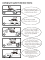
TO R E P L A C E L I G H T

To replace the LED light
should be undertaken by a
qualified electrician or a
competent person. Always
use the light no more
than rating.
Do not connect the air
outlet to chimney flues or
combustion gas ducts
Do not leave naked
flames under the hood
In case of any damage
to power cable, replace
the broken cable with a
new one by qualified
person.
Do clean the hood
correctly in accordance
with instruction stated or it
might cause the possibility
of fire accident


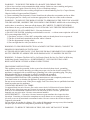
WARNING – TO REDUCE THE RISK OF A RANGE TOP GREASE FIRE:
a) Never leave surface units unattended at high settings. Boilovers cause smoking and greasy
spillovers that may ignite. Heat oils slowly on low or medium settings.
b) Always turn hood ON when cooking at high heat or when flambeing food (i.e.Crepes Suzette,
Cherries Jubilee, Peppercorn Beef Flambe’).
c) Clean ventilating fans frequently. Grease should not be allowed to accumulate on fan or filter.
d) Use proper pan size. Always use cookware appropriate for the size of the surface element.
WARNING – TO REDUCE THE RISK OF INJURY TO PERSONS IN THE EVENT OF A RANGE
TOP GREASE FIRE, OBSERVE THE FOLLOWING: SMOTHER FLAMES with a close-fitting lid,
cookie sheet, or metal tray, then turn off the burner. BE CAREFUL TO PREVENT BURNS.
If the flames do not go out immediately, EVACUATE AND CALL THE FIRE DEPARTMENT.
b) NEVER PICK UP A FLAMING PAN – You may be burned.
c) DO NOT USE WATER, including wet dishcloths or towels – a violent steam explosion will result.
d) Use an extinguisher ONLY if:
1) You know you have a Class ABC extinguisher, and you already know how to operate it.
2) The fire is small and contained in the area where it started.
3) The fire department is being called.
4) You can fight the fire with your back to an exit.
WARNING: TO PROVIDE PROTECTION AGAINST ELECTRIC SHOCK, CONNECT TO
PROPERLY GROUNDED OUTLETS ONLY.
A UTILISER SEULEMENT AVEC UNE TROUSSE DE RACCORDEMENT DE CORDON DE
HOTTE VÉRIFIÉE ET APPROUVÉE POUR EMPLOI AVEC CE MODÈLE DE HOTTE.
WARNING - To Reduce The Risk Of Fire Or Electric Shock, Do Not Use This Fan With Any
Solid-State Speed Control Device. AVERTISSEMENT : NE CONVIENT PAS A DES
REGULATEURS DE VITESSE A SEMI-CONDUCTEURS.
GROUNDING INSTRUCTIONS
This appliance must be grounded. In the event of an electrical short circuit, grounding
reduces the risk of electric shock by providing an escape wire for the electric current. This
appliance is equipped with a cord having a grounding wire with a grounding plug. The plug
must be plugged into an outlet that is properly installed and grounded.
WARNING – Improper grounding can result in a risk of electric shock.
Consult a qualified electrician if the grounding instructions are not completely understood,
or if doubt exists as to whether the appliance is properly grounded.
Do not use an extension cord. If the power supply cord is too short, have a qualified electrician
install an outlet near the appliance
CONSIGNES DE MISE A LA TERRE
Cet appareil doit être mis à la terre. En cas de court-circuit, le fil de mise à la terre limite le
risqué de choc électrique parce qu’il assure le retour du courant à la terre. L’appareil est
livré avec un cordon muni d’un fil de terre et d’une fiche de mise à la terre, qui doit être
branchée sur une prise mise à la terre correctement installée.
AVERTISSEMENT — Une mise à la terre incorrecte peut entraîner des risques de choc
électrique. Consulter un électricien compétent en cas de doute sur ces consignes de mise
à la terre ou en cas d’incertitude concernant la mise à la terre correcte du circuit sur lequel
l’appareil est branché.
Ne pas utiliser de cordon de rallonge. Si le cordon d’alimentation est trop court, faire installer
une prise par un électricien compétent à proximité de l’appareil.
WARNING - TO REDUCE THE RISK OF FIRE, USE ONLY METAL DUCT WORK.

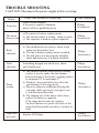
TROUBLE SHOOTING
CAUTION: Disconnect the power supply before servicing.
Status
Cause and Method of Repairing
Tools required
No power
Check circuit breakers
If the power supply is damaged,
please call for a qualified person
Philips
Screwdriver
Philips
Screwdriver
Philips
Screwdriver
Philips
Screwdriver
Philips
Screwdriver
Philips
Screwdriver
The motor
does not run
a).The motor is broken, replace motor.
b). The switch control is broken, replace switch.
c). The capacitor is broken, replace capacitor.
Body
vibration
a).The installation is not correct, check it and
make sure the hood is level.
b). The fan is broken, replace motor assembly.
c). The fan motor was not properly installed,
check and make sure it is firmly installed.
Noise
vibration
Something dropped into the blower, check
and clean blower.
Weak
suction
a). The distance from the range hood to cooking
surface is too far, make sure the distance
between bottom of the hood to cooking surface
is minimum 24" to maximum 27".
b). Windows, doors and drafts can effect the
performance of the range hood.
c). There are other air conditions effecting the
vent pipe, make sure lower vent pipe’s exit
is in a downward direction.
d). The running rate of the motor slows down,
replace the motor or capacitor.
If the range hood is near the window,
the best solution is to protect the back of the
range hood from draft caused by a window or
door.
Light does
not work
Replace LED lamp.
-
 1
1
-
 2
2
-
 3
3
-
 4
4
-
 5
5
-
 6
6
-
 7
7
-
 8
8
-
 9
9
-
 10
10
-
 11
11
-
 12
12


dans d''autres langues
- English: Empava EMP-30RH06 User manual
Autres documents
-
 Trifecte TRI-RS-8190F2 Manuel utilisateur
-
 Trifecte TRI-RS-8190F2 Manuel utilisateur
-
 Trifecte TRI-RS-7275F1 Manuel utilisateur
-
Zephyr CTPE60BSX Manuel utilisateur
-
Faber Cylrindra Isola 15 SS Guide d'installation
-
Yes AK7448AS Manuel utilisateur
-
-
ELICA ELG636S2 Use, Care, and Installation Guide
-
Zephyr ZGE-E30AS290 Manuel utilisateur
-


