
CASSETTA PER SOTTOSTAZIONE DI REGOLAZIONE DA
PARETE / INSTALLAZIONE VALVOLA R414M E R414D
047U23258 gennaio 2012
ISO
9001
0006/7
ISO
14001
0032A/2
OHSAS
18001
0064L/0
CASSETTA PER SOTTOSTAZIONE DI REGOLAZIONE DA
PARETE / INSTALLAZIONE VALVOLA R414M E R414D
047U23258 gennaio 2012
ISO
9001
0006/7
ISO
14001
0032A/2
OHSAS
18001
0064L/0
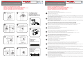
Installazione cassetta R508M mediante dima R504
Installation co ret R508M au moyen du support de xation R504
Einbau eines Kunststo kastens R508M mit Hilfe einer Montageschiene R504
Установка блока R508M с использованием шаблона R504
Installation of the R508M cabinet by means of R504 template
- Posizionare la valvola nella cassetta e ssare la calotta.
- Positionner le robinet dans le co ret et xer le raccord du coude au robinet.
- Positionieren Sie das Ventil im Kasten an der dafür vorgesehenen Stelle und ziehen Sie die Überwurfmutter an.
- Поместить клапан в ящик и закрепить гайку
- Position the valve into the cabinet and x the nut.
1
- Fissare la valvola ai tubi di plastica in modo che la lunghezza dei tubi corrisponda alla posizione prevista della cassetta R508M. Montare la valvola di s ato aria R88/1 e la
testa termostatica R456 con relativa guarnizione sagomata (tipo B).
- Fixer le robinet aux tubes en plastique de façon à ce que la longueur de tube corresponde à la position prévue pour le co ret R508M. Monter le purgeur d’air R88/1 et la
tête thermostatique R456 avec le joint correspondant (type B).
- Bringen Sie das Ventil am Kunststo rohr so an, dass das Rohr spannungsfrei montiert werden kann. Montieren Sie den automatischen Schwimmerentlüfter R88/1 und den
Thermostatkopf R456 mit der dazu passenden Rosette (Typ B).
- Прикрепить клапан к пластиковым трубам, так что бы длина трубы соответствовала предрасположению ящика R508M. Установите клапан выпуска воздуха R88 /
1 и термовентиль R456 с уплотнительным кольцом (тип B).
- Fix the valve to the plastic pipes so that the pipe length correspond to the expected position of the R508M cabinet. Mount the R88/1 automatic air vent valve and the R456
thermostatic head with the relative shaped gasket (type B).
2
- Montare la valvola nella cassetta premendo contro gli agganci a clips. Montare, mediante due viti, la dima R504 sulla cassetta R508M.
- Monter le robinet dans le co ret en appuyant contre les clips. Monter, avec deux vis, le support de xation R504 sur le co ret R508M.
- Montieren Sie das Ventil in die dafür vorgesehen Halterung. Mit Hilfe von zwei Schrauben montieren Sie die Montageschiene R504 in den Kasten R508M.
- Установите клапан в ящик, нажимая на клипы блокировки. Установить, с помощью двух винтов шаблон R504 на ящик R508M.
- Mount the valve into the cabinet by pressing against the clips. By means of two screws, mount the R504 template into the R508M cabinet.
3
- Posizionare la cassetta con la livella e ssarla alla parete.
- Positionner le co ret avec un niveau, et le xer à la paroi.
- Bringen Sie den Kasten in eine waagerechte Position und befestigen Sie ihn an der Wand.
- Установить ящик с помощью уровня и закрепить на стене.
- Position the cabinet with the level and x it to the wall.
4
- Avvitare la vite che mantiene ssata la valvola negli agganci a clips in modo che la testa termostatica R456 risulti nella posizione più corretta.
- Serrer la vis qui xe le robinet dans les clips, de façon que la tête thermostatique R456 se trouve dans la meilleure position.
- Ziehen Sie die Schrauben so fest an, dass der Thermostatkopf R456 optimal positioniert ist.
- Затянуть винт, который держит клапан фиксированным в клипах блокировки так, что термовентиль R456 находится в правильной позиции.
- Screw the screw that keeps the valve xed into the clips, so that R456 thermostatic head is in the most correct position.
5
- Montare la zanca R503A che evita lo scorrimento dei tubi dovuto alla dilatazione termica.
- Monter le guide tube R503A pour éviter le glissement des tubes, dû à la dilatation thermique.
- Montieren Sie den Rohrhalter R503A so, dass das Rohr aufgrund seiner thermischen Ausdehnung folgen kann.
- Установить деталь R503A, которая предотвращает скольжение труб из-за теплового расширения.
- Mount the R503A bracket that avoids the pipe sliding due to the thermal expansion.
6
- Fissare con cemento la cassetta. Togliere la dima R504.
- Fixer le co ret dans la paroi au moyen de mortier. Enlever le support de xation R504
- Fixieren Sie den Kasten mit einem Schnellbinder.
- Зафиксировать ящик с использованием цемента. Удалить шаблон R504.
- Fix the cabinet with cement. Remove the R504 template.
7
- Dopo aver ultimato la parete (intonaco o tappezzeria o altro rivestimento) ssare il coperchio con le viti e la relativa guarnizione sagomata (tipo A).
- Après avoir achever la paroi (crépi, tapisserie ou autre revêtement), xer le couvercle avec les vis et la garniture correspondante (type A).
- Nach dem Verputzen und Tapezieren befestigen Sie den Deckel inklusive der Rosette (Typ A) mit den entsprechenden Schrauben
- После завершения строительства стены (штукатурки или обоев или другого покрытия) зафиксировать крышку винтами и формованной прокладкой (тип A).
- After completion of the wall (plaster or tapestry or other covering), x the cover with the screws and the respective shaped gasket (type A)
8
- Per completare l’assemblaggio con testa R470: ssare coperchio con relative viti; inserire guarnizione sagomata (tipo B); applicare testa R470, facendo attenzione a
mantenere il segno di riferimento della scala verso l’alto.
- A n de compléter l’assemblage avec la tête thermostatique R470 ; xer le couvercle avec les vis, insérer la collerette préformée dans l’ori ce (type B), positionner la tête
thermostatique R470 en prenant soin de garder l’indicateur de position vers le haut.
- Bei Verwendung des Thermostatkopfs R470 verwenden Sie bitte die Rosette Typ B; achten Sie darauf, dass die Einstellposition oben steht.
- Для завершения сборки с термовентилем R470: зафиксировать крышку винтами, вставить уплотнение (тип B), установить термовентоль R470.
- Completion of the R470 head assembly: x the cover with the appropriate screws; t in the shaped gasket (type B); apply the R470 head paying attention to keep the
reference mark upwards.
9
- Per poter smontare la testa termostatica agire nel seguente modo: pigiare la guarnizione con entrambe le mani verso l’interno della cassetta; svitare le viti che ssano il
coperchio alla cassetta; smontare il coperchio; rimuovere la testa termostatica.
- Pour enlever la tête thermostatique, procédez comme suit : appuyez sur le joint avec les deux mains a n de faire traverser le couvercle au joint. Dévissez les vis qui
maintiennent le couvercle, retirez le couvercle et enlevez la tête thermostatique.
- Zur Demontage des Thermostatkopfs drücken Sie die Rosette B mit beiden Händen in das Innere des Montagekastens; anschließend lösen Sie die beiden Schrauben und
nehmen den Deckel ab; dann entfernen Sie den Thermostatkopf.
- Для того чтобы снять термовентиль, выполните следующие действия: нажмите прокладки обеими руками к внутренней стороне коробки; отвинтите винты на
крышке кассеты, снимите крышку, а затем удалите термовентиль.
- In order to take out the thermostatic head: press the gasket with both hands towards the cabinet inside; unscrew the screws that x the cover to the cabinet; dismount the
cover; remove the thermostatic head.
10
Installazione cassetta R508M mediante dima R504
Installation co ret R508M au moyen du support de xation R504
Einbau eines Kunststo kastens R508M mit Hilfe einer Montageschiene R504
Установка блока R508M с использованием шаблона R504
Installation of the R508M cabinet by means of R504 template
• PER ASSEMBLAGGIO TESTA R470
• POUR ASSEMBLER LA TÈTE R470
• MONTAGE EINES THERMOSTATKOPFS R470
• Для сборки термовентиля R470
• ASSEMBLY OF R470 THERMOSTATIC HEAD
1
3
5
7
2
4
6
8
9
10
• GUARNIZIONE TIPO A
• GARNITURE TYP A
• ROSETTE TYP A
• Уплотнительная прокладка тип А
• GASKET TYPE A
• GUARNIZIONE TIPO B
• GARNITURE TYPE B
• ROSETTE Typ B
• Уплотнительная прокладка тип В
• GASKET TYPE B

CASSETTA PER SOTTOSTAZIONE DI REGOLAZIONE DA
PARETE / INSTALLAZIONE VALVOLA R414M E R414D
047U23258 gennaio 2012
ISO
9001
0006/7
ISO
14001
0032A/2
OHSAS
18001
0064L/0
CASSETTA PER SOTTOSTAZIONE DI REGOLAZIONE DA
PARETE / INSTALLAZIONE VALVOLA R414M E R414D
047U23258 gennaio 2012
ISO
9001
0006/7
ISO
14001
0032A/2
OHSAS
18001
0064L/0
La protezione da cantiere consente di parzializzare la portata della valvola: ruotando in senso antiorario si apre la valvola mentre con rotazione
oraria si ottiene la sua chiusura. Il volantino manuale chiuso a fondo o la protezione da cantiere con cappuccio chiuso a fondo consentono di
superare abbondantemente pressioni statiche di 10 bar con impianto spento. Si sconsiglia, in ogni caso, di effettuare prove di tenuta in pressione
dell’impianto prima del collegamento dei corpi scaldanti onde evitare, in caso di danneggiamenti accorsi al meccanismo, di provocare allagamenti.
Le capuchon de chantier
permet de régler le débit dans le robinet :
en tournant la partie rouge ou le volant dans le sens des contraire des aiguille
d’une montre on ouvre le robinet, alors que dans le sans des aiguilles d’une montre on ferme le robinet. Le volant manuel fermé à fond ou le
capuchon de chantier fermé à fond permettent de supporter une pressions statiques largement supérieure a 10 bar. On déconseille dans tous
les cas de faire les essais d’étanchéité en pression de l’installation, avant le raccordement des radiateurs, pour éviter de provoquer des inonda-
tions en cas de mécanisme endommagé.
Mit Hilfe des Handrads lässt sich das Ventil schrittweise öffnen. Durch Drehen entgegen dem Uhrzeigersinn öffnet sich das Ventil, durch
Drehen im Uhrzei-gersinn schließt es. Ist die Schutzkappe ganz geschlossen oder das Handrad ganz geschlossen, lasst sich bei abgeschalteter
Heizungsanlage der statische drucken über den ganzen Bereich bis 10 bar einstellen. Es ist jedoch nicht ratsam, eine Druckprüfung der Anlage
vor Anbringen der Heizkörper oder anderer Heizelemente durchzuführen, da bei beschädigter Schutzkappe Wasser austreten kann.
The protection cap allows to divide in parts the delivery of the valve. By rotating it counter clockwise the valve opens, while with a clockwise
rotation it closes. The fully closed manual handwheel or the fully closed protection cap allow to go generously over the static pressuresof 10 bar
with switched o system. However, it is not recommended that pressure testing of the system is carried out prior to the tting of the radiators,
or other heating elements, since ooding may occur in the event of damage to the protection cap or to the handwheel.
Защитное устройство позволяет регулировать пропускную способность клапана. Eсли повернуть красный колпачок по часовой
стрелке, то клапан закроется, если против – откроется. B выключенном состоянии пластиковый маховичок при закрытом колпачке
на дне позволяет выдерживать повышенный уровень статических нагрузок до 10 бар. В любом случае, чтобы избежать повреждений
механизма или разрыва/ протечки‚ не рекомендуется проводить испытания на герметичность установки под давлением до соединения
радиаторов
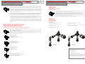
Montaggio delle teste termostatiche Giacomini sulla valvola
Montage de les têtes thermostatiques Giacomini sur le robinet
Montage des Giacomini Thermostatkopfs auf das Ventil
Assembly of Giacomini thermostatic heads to the valve
Монтаж термостатических головок Джакомини с клапаном Джакомини
Nel caso di valvola con protezione da cantiere, dopo aver svitato in senso antiorario il cappuccio rosso, sganciare la protezione da cantiere
facendo leva sulla base mediante l’ausilio di un cacciavite.
Après avoir complètement ouvert le capuchon rouge dans le sens inverse des aiguilles d’une montre, enlever le capuchon de chantier en faisant
levier à la base du capuchon avec un tournevis.
Drehen Sie die rote Kappe entgegen dem Uhrzeigersinn ganz ab. Danach wird mit einem einen Schraubendreher die Schutzkappe abgehebelt.
Unscrew the red cap fully counter clockwise and remove the protection cap by using a screwdriver as a lever.
Для монтажа термостатических головок Джакомини с клапаном после поворота против часовой стрелки красного кожуха следует
снять пластиковый маховичок при помощи отверти.
Aprire completamente la testa
Ouvrir complètement la tête
Thermostatkopf ganz aufdrehen.
Open fully the head.
Откройте полностыо термостатическую головку.
Agganciare la testa alla valvola
En foncer la tête sur le robinet
Thermostatkopf an das Ventil anbringen.
Connect the head to the valve.
Защелкните головку на клапане
Chiudere completamente la testa.
Fermer complètement la tête.
Thermostatkopf ganz zudrehen.
Close fully the head.
Полностыю закройте головку.
Aprire la testa nella posizione di taratura desiderata.
Positionner la tête sur la position désirée.
Thermostatkopf so weit aufdrehen, bis er sich in der gewünschten.
Open the head into the desired calibration position.
Откройте головку до нужного уровня.
Sostituzione O-Ring
Remplacement joint
O-Ring ersatz
Замена уплотнительного кольца
O-ring replacement
In caso di manutenzione é possibile sostituire l’anello O-ring dell’asta svitando la calottina del vitone mediante l’ausilio di una chiave esagonale
da 11 mm. Questa operazione può essere effettuata anche ad impianto funzionante.
Dans le cadre d’une maintenance de l’installation il est possible de changer le joint O-ring situe sur l’axe du mécanisme. Pour cela on dévissera,
à l’aide d’une clef hexagonale de 11 mm, l’écrou situe sur l’axe. Cette opération est possible l’installation étant sous pression.
Zu Wartungszwecken lässt sich der O-Ring auf der Spindel im Ventil ersetzen, indem man die kleine Sechskant-Überwurfmutter mit einem 11
mm. Schraubenschussel löst. Dieser Vorgang ist möglich, ohne zuvor das Wasser aus der Anlage ablassen zu müssen.
For maintenance purposes, it is possible to replace the O-ring seal on the valve stem by unscrewing the small hexagonal retaining nut using an
11 mm spanner. This operation may be carried out without draining the system.
В случае необходимости проведения ремонтных работ, заменить уплотнительное кольцо можно, открутив гайку при помощи шестигранного
ключа на 11мм. Эта операция может быть осуществлена также при работе оборудования.
Pressione max d’esercizio per applicazioni manuali: PN16
Temperatura max d’esercizio: 110°C
Max Betriebsdruck für manuellen Anwendungen: PN16
Max Betriebstemperatur: 110°C
Max working pressure for manual applications: PN16
Max working temperature: 110°C
Dati tecnici
Données Techniques
Technische Daten
Технические данные
Technical data
Pression max de service pour applications manuelles: PN16
Température max de service: 110°C
Максимальное рабочее давление клапанов с механической регулировкой: PN16
Максимальная рабочая температура : 110°C
Altre informazioni
Per ulteriori informazioni consultare il sito www.giacomini.com
o contattare il servizio tecnico:
℡ +39 0322 923372
6 +39 0322 923255
Questa comunicazione ha valore indicativo. Giacomini S.p.A. si riserva il diritto di
apportare in qualunque momento, senza preavviso, modi che per ragioni tecniche
o commerciali agli articoli contenuti nella presente comunicazione. Le informazioni
contenute in questa comunicazione tecnica non esentano l’utilizzatore dal seguire
scrupolosamente le normative e le norme di buona tecnica esistenti.
Giacomini S.p.A. Via per Alzo, 39 I-28017 San Maurizio d’Opaglio (NO) Italy
G 3/8”
ø 18
ø 18
R414D
G 3/8”
ø 18
ø 18
R414M
-
 1
1
-
 2
2


Giacomini R508M Mode d'emploi
- Taper
- Mode d'emploi
- Ce manuel convient également à
dans d''autres langues
- italiano: Giacomini R508M Istruzioni per l'uso
- English: Giacomini R508M Operating instructions
- Deutsch: Giacomini R508M Bedienungsanleitung
Documents connexes
Autres documents
-
Tektronix AM 502 Manuel utilisateur
-
MasterCool BLACK SERIES MINI-FOLD R134a COMPACT 2-WAY ALUMINUM MANIFOLD Mode d'emploi
-
Sony XM554ZR - XM Amplifier Manuel utilisateur
-
Silvercrest Classic Model L Operating Instructions And Safety Advices
-
Tamiya Scania R470 Highline Le manuel du propriétaire
-
Wolf ZP-3 DHW Installation Instructions Manual
-
 Mitsubishi Electronics MAC-399IF-E Manuel utilisateur
-
JVC KD-R570 Manuel utilisateur
