
Tektronix. Inc.
P.O
Box 500
Beaverton.
Oregon
070-1582-01
Product
Group 75
l^ronix-
COMMITTED
TO
EXCELLENCE
PLEASE
CHECK
FOR
CHANGE
INFORMATION
AT
THE
REAR
OF
THIS
MANUAL.
AM 502
DIFFERENTIAL
AMPLIFIER
Francais
Deutsch
INSTRUCTION
MANUAL
97077
Serial
Number
First
Printing
MAY
1983
Revised
OCT
1986

Copyright
^
1973, 1978 Tektronix.
Inc. All rights
reserved.
Contents of this
publication
may
not be reproduced in
any
form
without the
written permission
of Tektronix, Inc.
Copyright ©1973,
1
978
durch Tektronix,
Inc. Alle Rechtevorbe-
halten.
Der Inhalt
dieser Publikation
darf
ohne Genehmigung
von Tektronix,
Inc.
nicht
weitergegeben
werden.
Products of Tektronix, Inc
and its
subsidiaries
are covered
Produkte von
Tektronix,
Inc.
und seinen
Tochtergesellschaften
by U
S.
and foreign
patents
and/or pending
patents sind
durch
US-
und
Auslandspatente
und/oder
schwebende
Patente
abgedeckt.
TEKTRONIX, TEK,
SCOPE-MOBILE,
and
are reg-
istered trademarks
of Tektronix,
Inc.
TEKTRONIX,
TEK,
SCOPE-MOBILE
und
sind geschutzte
Warenzeichen
von Tektronix,
Inc.
Printed in
U S A. Specification
and price change
privileges
are reserved.
Gedruckt in
U.S.A. Spezifikations-
und PreisSinderungen
bleiben
vorbehalten.
Copyright
@1973,
1978
TEKTRONIX
INC.
Tous droits r6serv6s.
Le contenu
de
ce
manuel
ne
peut etre
reproduit
sous guelque for-
me
que ce soit
sans
I'accord
de Tektronix Inc.
Tous les
produits
TEKTRONIX
sont brevet^s
US et Etranger
et
les
logotypes
TEKTRONIX,
TEK
SCOPE
MOBILE,
sont
diposes
. kS
Imprimi
aux USA.
TEKTRONIX
se
riserve
le
droit
de modifier
:
caractiristiques
et
pnx
dans le cadre
de
diveloppements techno-
logiques
©
1973,1978 h
O
~
7.^i-
TEKTRONIX,
TEK,
SCOPE-MOBILE,^
h
D
-
XT,
^^ICTEDSiJ
< SsSfifl
nit
INSTRUMENT
SERIAL
NUMBERS
Each instrument
has
a
serial number
on
a panel insert,
tag,
or stamped on
the chassis. The
first
number
or letter
designates the
country of
manufacture.
The
last five digits
of
the
serial
number are
assigned
sequentially
and
are
unique
to
each
instrument.
Those
manufactured
in
the
United
States have
six unique digits.
The
country
of
manufacture
is
identified
as
follows:
BOOOOOO Tektronix,
Inc.,
Beaverton, Oregon,
USA
100000
Tektronix
Guernsey,
Ltd., Channel
Islands
200000
Tektronix United
Kingdom,
Ltd.,
London
300000 Sony/Tektronix,
Japan
700000 Tektronix
Holland, NV,
Heerenveen,
The
Netherlands

AM 502
TABLE
OF
CONTENTS
Page
Section 1
Operating
Instructions
1-1
ENGLISH VERSION
FRENCH VERSION
GERMAN
VERSION
JAPANESE
VERSION
Section
2
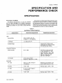
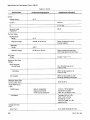
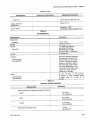
SPECiFiCATiON AND PERFORMANCE
CHECK
2-1
WARNING
THE FOLLOWING SERVICING
INSTRUCTIONS
ARE FOR
USE
BY QUALIFIED
PERSONNEL
ONLY.
TO AVOID PERSONAL
INJURY, DO NOT
PERFORM ANY SERVICING
OTHER THAN THAT
CONTAINED IN OPERATING INSTRUCTIONS
UNLESS YOU ARE QUALIFIED
TO DO
SO.
Page
Section 4 MAiNTENANCE AND iNTERFACiNG
iNFORMATION
4-1
Sections CIRCUIT DESCRiPTiON
5-1
Sections OPTiONS
6-1
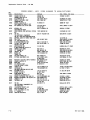
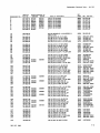
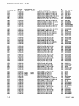
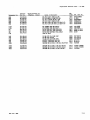
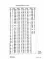
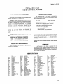
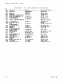
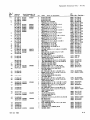
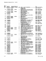
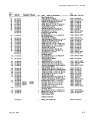
Section 7 REPLACEABLE ELECTRiCAL PARTS
7-1
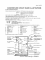
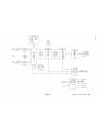
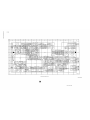
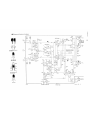
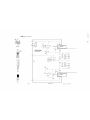
Section 8 DiAGRAM AND
CIRCUiT
BOARD
iLLUSTRATION
8-1
Section
9
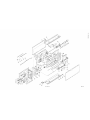
REPLACEABLE MECHANICAL PARTS
AND EXPLODED VIEW
9-1
Section
3
ADJUSTMENT
3-1
CHANGE
INFORMATION
REV
C
SEP
1980
i

AM 502
1582-1
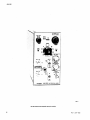
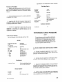
AM 502
Differential
Amplifier
plug-in module.
II
REV
C SEP 1980

Section
1
—AM
502
OPERATING
INSTRUCTIONS
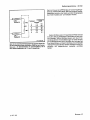
INTRODUCTION
Description
The
AM
502
is a
dc-coupled
differential
amplifier
with
excellent
common-mode
rejection
capabilities
and
high
gain
for
low
voltage
measurements.
The
dc
offset
capabili-
ty
permits
nulling
up
to
1 volt
dc, so
that
low
level,
low
frequency
signals
impressed
on a dc
level
can
be
amplified
without
the
degradation
often
introduced
by
ac
input
coupling.
High
and low
frequency
-3
dB
points
can
be
selected
at
the
front
panel to
suit the
application.
Signal
inputs
and
outputs
are
available
at
the
rear
connector
as
well as
at
the
front
panel.
A
front
panel
lamp
indicates
most
overrange
conditions
of
excessive
input
signal,
excessive
gain, or
excessive
offset.
The
input
circuit
can be
represented
by
approximately
1
megohm
to
ground
paralleled
by
approximately
47
picofarads.
The
input
impedance
can be
raised
to
about
200
megohms
with
the
removal
of a
jumper.
Overload
protection
is
provided by
fuses
in
series
with
the
input
which
open
when
large
amounts
of
current
flow
due
to
overloading
conditions.
A
STEP
GAIN DC
BALANCE
control
is
provided to
adjust
for zero
shift as
the
gain
switch
is
changed
from one
position to
another.
The
DC
OFFSET
COARSE
and
FINE
controls
give
offset up
to
±1 volt dc
potential
difference
at the
input
connectors.
The
amplifier
internal
bias
is
changed
to
accomplish
the
offset.
The LF
-3
dB
switch
must be
in
the
DC
OFFSET
position
to
actuate
these
controls.
The
HF
-3
dB
switch
is
used
to
reduce
the
upper
bandwidth
limit
as
necessary
to
improve
the
signal-to-
noise
ratio when
using
the
AM
502 in
low-frequency
applications.
The LF
-3
dB
control
increases
the lower
bandwidth
frequency.
Use
of
the
pre-charging
feature
prevents
surge
currents,
due
to
charging
the
ac
coupling
capacitor,
from
damaging
the
circuit
under
test.
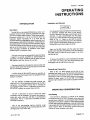
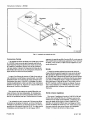
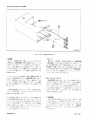
Installation and
Removal
Turn the
power
module
off
before
inserting
the
plug-
in;
otherwise,
damage
may
occur
to the
plug-in
circuitry.
Because
of
the
high
current
drawn
by
the
AM
502,
it
is
also
recommended
that
the
power
module
be
turned
off
before
removing
the
AM
502.
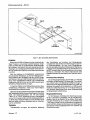
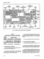
Refer
to
Fig.
1-1.
Check
to
see that
the
plastic
barriers
on the
interconnecting
jack of
the
selected
power
module
compartment
match
the
cut-outs
in
the
AM
502
circuit
board
edge
connector.
Align
the
AM
502
chassis
with
the
upper
and
lower
guides
of
the
selected
compartment.
Push
the
module
in
and
press
firmly
to
seat
the
circuit
board
in
the
inter-
connecting
jack.
To
remove
the
AM
502,
pull on
the
release
latch
located
in the
lower
left
corner,
until
the
interconnecting
jack
disengages
and
the
AM
502
will
slide out.
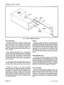
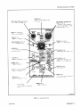
Controls
and
Connectors
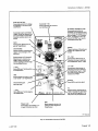
Refer
to Fig.
1-2.
Even
though
the
AM
502
is
fully
calibrated
and
ready
to
use,
the
functions
and
actions
of
the
controls
and
connectors
should
be
reviewed
before
attempting
to
use
it.
Pull the
Power
switch
on
the
power
module
to
apply
power
to
the
AM
502.
The
POWER
indicator
light
indicates
when
power
is
applied to
the
AM
502.
OPERATING
CONSIDERATIONS
Overheating
The
AM 502
is
designed
to
operate
at
an
ambient
temperature
from
0°
to
4-50°
C.
However,
when
operating
several
power
supplies
in a
multi-plug-in
power
module,
especially
at
low
output
voltages,
or
when
operating
ciose
to
other
heat-producing
equipment,
internal
temperature
may
exceed
safe
limits
and
actuate
a
thermal
cutout
in
the
power
module.
Refer to
the
power
module
instruction
manual
for
more
complete
information.
REV
D
SEP
1980
English
1-1

Operating
instructions—AM 502
Fig.
1-1.
Plug-in
installation
and removal.
Input
Connections
Unshielded
test leads can
be used to connect the
AM
502 to a signal
source when
a high-level, low-frequency
signal is
monitored at
a
low
impedance point.
However,
when any
of these
factors is missing,
it becomes in-
creasingly
important
to
use shielded signal cables. In
all
cases, the
signal-transporting
leads should
be kept
as
short
as practical.
When making
single-ended
input
measurements
(conventional
amplifier
operation),
be sure
to establish
a
common
ground connection
between the
device
under
test
and the AM
502.
The shield
of
a coaxial
cable is
normally
used
for
this
purpose.
See Fig.
1-3
for
reference.
Push
the GND
button for
the input
not
connected
to the
device under
test.
In some
cases differential
measurements require
no
common
chassis
ground connection,
and therefore
are
less
susceptible
to interference
by
ground-loop
currents.
Probes
Attenuator
probes
decrease the resistive-capacitive
loading
of
a
signal
source. They
also extend the
measure-
ment
range of the AM
502 to substantially higher voltages.
Some
measurements
require a higher resistance
input
to
the
AM
502,
with
very little source
loading
or signal
attenuation.
In such situations
use
a
FET
probe or
the
high-impedance input
provision of
the AM
502. Contact
your Tektronix
Representative
for
further information
on
probes.
High
Impedance
Input
T
0
raise the internal
input
impedance of
the AM
502
to
about 200
megohms,
remove the P40 plug
(Fig.
3-1
).
Make
certain the
attenuator is in the
NORM mode.
Signal
source
impedance
now becomes
an important
factor. For
exam-
ple,
a
100
picoampere
gate current through
10
megohms
produces
a one-millivolt
offset. This
offset may
result
in
significant
error when small
voltages are
measured.
Consider the
change in
the source operating
characteristics
due
to loading
by the signal input
cables.
The
circuit
at
the input
connectors can
be represented
by
approximately
1 megohm
to ground paralleled
by ap-
proximately
47
picofarads. Two feet
of
50
ohm
coaxial
cable
increases the parallel
capacitance
by about
60
picofarads,
which could be excessive in many
situations.
To minimize
these effects,
use a
higher
impedance
cable
or
an
attenuator
probe,
Input
Overloading
When
measuring unknown
dc
voltages,
push the
-^100
pushbutton
in, and
start
with
the
100
position on the
GAIN
switch.
Increase
the GAIN
switch setting and
finally
release the -rlOO
pushbutton until
a
suitable
output
signal
is obtained.
If the input
circuit of the
AM
502
is
overdriven,
large
amounts of current
will flow,
opening
the
protective
fuses.
English
1-2
REV
C SEP
1980

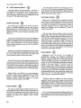
Operating Instructions
—AM
502
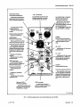
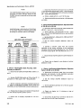
STEP GAIN
DC BAL Control
Adjusts
dc
balance
in the
preamplifier stage.
Variable Gain
Control
con-
tinuously
variable.
Calibrated
in the
cw
position.
GAIN Switch
Selects amplifier gain.
OVER RANGE
Indicator
When lit,
indicates most
over-
range conditions.
^100
Pushbutton
Divides
GAIN
switch setting
by 100.
STEP
SAJM
DCBM.
OC
»fS£T
iW
FIH£-«-C0ARSM
DC
OFFSET COURSE and
FINE
Controls
f
Provides
internal offset of
approximately ±1 V to
input
signal.
LF
—3
dB
switch must
be in the
DC
OFFSET
position
for controls
to
operate.
POWER
Indicator
When
lit,
indicates power is
applied.
AC
Pushbutton
Selects the input signal (ac or
dc)
into the negative side of the
preamplifier.
+ Input Connector
BNC connector for the
positive side of the amplifier.
GND Pushbutton
Grounds
+ amplifier input.
Ground Binding Post
Provides
a chassis return for
signals.
anv=f-Ac
oc
j
is.
WKSAeCOUH.
fts CHS
MWVt
wt
.
HF.3dB
U^>3dB
UIRTEO
BY
€oupu»e
miTp
Uc
oc
I ^
fET
OUTPUT
±5V
20mA
MAX
HF -3dB Switch
’
Selects
upper
—
3dB point of
the amplifier.
LF
—3
dB Switch
'
Selects lower
—3
dB point of
the amplifier
and activates DC
OFFSET controls.
OUTPUT Connector
BNC output
terminal
con-
nector.
—
Input Connector /
BNC connector for the
negative
side of the amplifier.
ROMtX®
AM S02l DIFFERENTIAL AMPL
AC
Pushbutton
Selects the
input signal
(ac
or
dc)
into the positive side
of
the
preampiifier.
Release Latch
Pull to
remove plug-in.
GND
Pushbutton
Ground
-
amplifier input.
REV C
SEP 1980
English
1-3

Operating
Instructions—AM
502
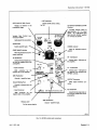
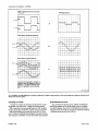
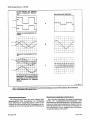
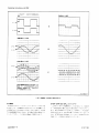
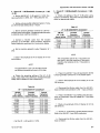
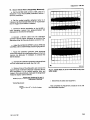
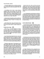
Waveforms
applied to
the
(+)
and
(—
)
input
connectors.
Signal
(square wave)
with an inter-
fering
line-frequency
component is
applied
to the
(+)
input.
The
interfering
signal
(sine wave) is
also
applied to
the
(—
)
input
connector.
The
resultant
display.
1582-5
Fig.
1
-3.
Waveforms
showing
differential
rejection
of a
common-mode
signal.
Resultant
waveforms show the
difference between
the two
signals.
Output
Connections
Make
output
connections
using a
bnc to
dual
binding
post
connector,
or
a
coaxial
cable
with at
least
one
bnc
connector.
To
prevent
current
limiting in
the
output stage,
do
not load
the
output
with
less than 250
ohms.
Output
current is
limited to
20
milliamperes.
Step Gain DC
Balance
If this
control is
misadjusted, the
dc
output
level will
shift
as
the
GAIN
switch
position
is
changed.
Push
both
GND
buttons
and
place
the GAIN
switch
in the 100
position.
Rotate the
GAIN
switch
from stop
to stop while
adjusting
the
STEP
GAIN DC
BAL
control
for node shift at
the
OUTPUT
terminal.
English
1-4
REV
C
SEP
1980

Operating
Instructions—
AM 502
DC
Offset
Coarse
and
Fine
Use these controls
to offset
up to
±1 volt
dc
potential
difference
at the input
connectors.
The
amplifier internal
bias
is changed
to accomplish
the
offset.
The
differential
rejection
capabilities
of the AM
502 are
not affected.
The
LF
-3dB switch must
be in
the
DC
OFFSET
position
to
activate these
controls.
HF
and
LF Bandwidth
Reduction
Use the HF
—
3dB switch
to reduce
the
upper
bandwidth
limit,
as
necessary,
to improve
the
signal-to-noise
ratio
when
using the AM
502 in
low-frequency
applications.
The
LF
—
3dB control
increases
the lower
bandwidth
frequency.
Use
this
control
to
reduce
dc drift,
when
raising
the lower
bandwidth
does
not
undesirably
reduce
the
bandwidth
for the
signal
being
measured.
Pre-Charging
Use
of this
feature
prevents
surge
currents,
due
to
charging
the
ac coupling
capacitor
in
the AM
502,
from
damaging
the circuit
under test.
Before
connecting
the
AM
502 to
a
signal
containing
a
dc component,
push
the
AC and
GND
pushbuttons.
Connect
the
input to the
circuit
under
test. Wait
about
one
second for the
coupling
capacitor
to charge.
Release
the GND
pushbutton,
and
the
coupling
capacitor
is
charged
to the
value
of the
dc
voltage
to
be measured.
Differential
Operation
A
differential
measurement
is made
by
connecting
each
of the
two
inputs to
selected
points
in the test
circuit.
The
input
to the
amplifier will
then
be the
difference
in
voltage
of the
two
selected
points.
Consideration
should
be given
to the
proper
connection
method
used
between
the
AM
502 and the
circuit
under
test; otherwise
improper
measurement
results
may
occur.
See Fig.
1-4
for
reference.
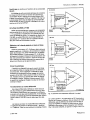
Differential
voltage
measurements
are
made
by apply-
ing
the
signals
to the
+input
and
—input
connectors.
Set
the
input
coupling
switches
to the
same
position,
AC or
DC,
depending
on
the
measurement
being
made.
In
differential
measurements,
only
the
voltage
difference
between
the
two
signals is
amplified.
Common
mode
signals
(common
in
amplitude,
phase,
and
frequency)
are
rejected.
See Fig. 1-3
A,
B,
and
C
for
reference.
Single-ended
measurements
often
yield
unsatisfactory
results
because
of the
interference
resulting
from
ground-
loop
currents
between
the AM
502 and the
device
under
test. In
other
cases. It may
be desirable
to eliminate
a dc
voltage
by
means other
than
the
use of
a blocking
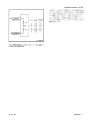
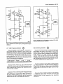
(A) Right
(B) Wrong
(C) Wrong
under test
not be
grounded
to
equipment
under
test
( 093
1 )
1
582-
1
3
Fig. 1-4.
Connecting
a diiferentiai
amplifier
to a
signal source.
capacitor,
which
could limit
the
low-frequency
response.
The
limitations
of
single-ended
measurements
are
effec-
tively
eliminated
by using
differential
measurements.
REV
C SEP
1980
English
1-5

Operating
Instructions—
AM
502
DC Offset
Operation
By using the FINE
and
COARSE DC
OFFSET
controls,
it is possible
to use the AM
502 differentially
in a
slide-back
mode,
to observe
a small signal
whose
dc
potential
difference
may
be considerable.
The offset
voltage
is
continuously
adjustable
from plus 1 volt to minus
1
volt,
and
is
internally
available
for all of
the GAIN
switch
positions.
The
LF -3dB switch must
be in the
DC OFFSET
position
to activate the offset circuit.
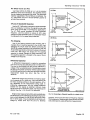
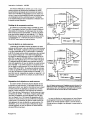
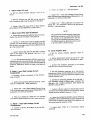
Common
Mode Rejection
Ratio
The
ability of
the AM 502 to reject
common-mode
signals is indicated
by
the
common-mode
rejection ratio
(cmrr). For example,
assume that
a signal consists of
unwanted
60 hertz
at 10 volts
peak-to-peak (common
mode connected
to both
inputs), plus
a desired signal at 1
millivolt
peak-to-peak (differentially
connected
to one
input).
The
AM
502
gain
is set at 200. The
output of the
AM
502 shows the
desired signal at an amplitude
of 0.2
volt
(1
millivolt
X
200),
and the
60 hertz signal
is viewed at an
amplitude of
0.02 volts. The cmrr
in this
application
is
100,000 to 1. This figure is
calculated
by
multiplying
the
value
of the common-mode
signal
(10
volt)
by
the
gain of
the
amplifier
(200)
for a
product of
2000 volts. This
product
is divided
by
the
observed
60
hertz
voltage
at the output
(0.02
volt)
and result is
the cmrr,
100,000 to 1 . It would,
of
course
be impossible
to
view
the 1 millivolt signal
superimposed
on the
60
hertz signal
by using single Input
methods.
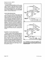
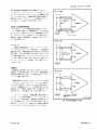
Degradation
of
Common
Mode Rejection
There are
a number of factors that
degrade common-
mode rejection
ratio (cmrr). The principal
requirement for
maximum
rejection
is for
the
common-mode
signal to
arrive
at the input
FET gates
at the same phase and
amplitude.
A difference of
only
0.01%
in the attenuation
ratios
of the input
attenuators will reduce the
rejection
ratio
to
10,000 to
1.
Also, any difference in
source
impedance will
degrade the rejection ratio.
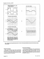
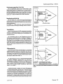
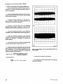
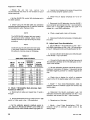
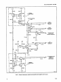
Figures
1-5
and
1-6
show common-mode
rejection degradation
due to
differences
in source impedance.
The frequency of the
common-mode
signal also affects the
common-mode
rejection
ratio. Generally,
as the frequency
of the Input
signal
increases,
the common-mode rejection
ratio is
more difficult
to maintain.
Fig.
1-5.
Relationship of
test point source Impedance
to the
amplifier
input Impedance and the apparent CMRR
caused
by (A)
large difference between
test-point impedances
and
(B) low
impedance test
points.
English
1-6
REV
D
SEP
1980

Operating
Instructions—
AM
502
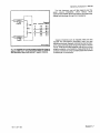
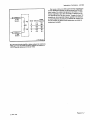
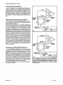
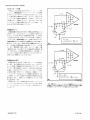
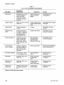
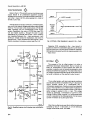
Fig.
1-6.
Simplified
input
circuit and
table
showing
the
change in
apparent
CMRR
due
to
10X probes
that are
within
1,
2,
and 3%
of
their
attenuation
values
(with
matched 1
megohm
resistors).
The
high
frequency
cmrr
will also
depend
upon
the
signal
source
impedance,
since
various
shunt
capacitances
between
the source
and the
input
gate
must
charge
and
discharge
through
that
impedance.
Outside
influences
such as
magnetic
fields
can
also
degrade
the
performance,
particularly
when
low
level
signals
are
involved.
Magnetic
interference
may
be
reduc-
ed
by
using
identical
signal
transporting
leads
to
the
two
inputs.
Twist
the
two leads
together
over
as
much
of
their
length as
possible.
Low-frequency
measurements
can be
similarly
protected by
using a
shielded
cable
that
contains
a
twisted
pair
of
conductors.
REV
A SEP 1980
English
1-7

Chapitre
1
•
AM
502
INSTRUCTIONS
D’UTILISATION
INTRODUCTION
Description
Le
tiroir
AM 502
est
un
amplificateur
differential
h
cou-
plage
continu
pr6sentant
un
excellent taux
de
rejection
en
mode
commun
ainsi
qu'un gain
Sieve. Ces
caracteristiques
destinent
cet
appareil
tout
particulierement
aux
mesures S
bas niveau.
II
possede
egalement
une commande
de
dScalage
de
tension
continue,
la plage de
compensation
de cette
com-
posante
continu
Stant
±
1 V.
Cette
compensation
permet
d'amplifier
les
signaux h
bas
niveau et k
faible
frequence et
superposSs k
une
composante
continue, tout
en Svitant
les
distorsions
souvent
introduites
par un
couplage
de type
alter-
natif. Les
limites
inferieure
et
superieure de
la
rSponse
en
frequence (S
—3
dB)
peuvent etre
sSlectionnSes
sur le
pan-
neau
avant, en
function de
I'application.
Les
entrSes et
sor-
ties
des
signaux
sont
disponibles
k
la fois sur
le
connecteur
de
I’interface
et
sur les
bornes
d'entrSe du
panneau
avant.
Uno latT
jno
citjiap
yit.l^3p^!m_3yant
inriiniifl _ftn
s'allumaD
L'emploi du
dispositif de
precharge
Svite les
surcharges
et
les
risques de
deterioration
en mode
couplage
alternatif.
Installation et
extraction
ATTENTION
Couper
Talimentation du
chassis avant
d'inserer
le
ti-
roir afin
d'eviter
de
det4riorer les
circuits
de
ce
dernier.
L 'AM
502
n4cessitant un fort
courant
d'alimentation,
// est
Sgalement recommande de
couper
Talimentation
avant
d'oter le
tiroir
du
chassis. Se
reporter a
la figure
1-1.
Verifier que
les detrompeurs
s’adaptent
bien
aux
encoches du
connecteur de
TAM 502.
Aligner les
rails
de
guidage de
TAM
502
avec
les guides du
comparti-
ment
s4lectionne.
Engager
le tiroir a fond et
appuyer
fermement
jusqu'a ce que
le circuit
imprime se
place
correctement.
P0Uf^exliailS_r^^^02^M^uy^|rrett^^errouilj|^
i

Instructions d'utilisation
-
AM
502
Connexions d'entr^e
II
est
possible
d'utiliser des cables non blind^s pour connec-
ter I'AM 502
d
une source
de
signal
d
grande
amplitude
et
basse fr^uence lorsque le signal
est issu d'une source
k
bas-
se
imp^ance.
Cependant, lorsque I'une
de ces conditions
n'est pas remplie, il
devient tres important d'utiliser des
ca-
bles blindes.
Dans
tous
les
cas,
ies conducteurs v^hiculant
le
signal doivent
etre aussi courts que possible.
Lorsque Ton effectue
des mesures
k
I'aide d'une seule en-
tree
(utilisation en amplificateur conventionnel),
il est
indis-
pensable
d'^tablir une connexion
de
masse commune entre
l'4quipement sous
test et
I'AM
502. Le blindage d'un cable
coaxial
est
g^n^ralement utilise
k
cet
effet. Pour information
d^taill^e voie la figure
1-3.
Appuyer
sur
le bouton GND pour
dfeonnecter I'entr^e
de
l'6quipement.
Dans certains
cas
de
mesures en mode differentiel, une
masse
commune n'est pas indispensable. En consequence,
ces
types de mesures sont moins susceptibles d'etre pertur-
bees
par les
problemes pos4s par I'interconnexion de masse.
II est
n^cessaire
de
tenir
compte
de
I'influence
des cables
de
liaisons
sur
les signaux
k
mesurer.
Le
circuit d'entr^e de
I'AM
502 est equivalent k une resistance d'environ 1 M£2 en
parallele
avec une capacite
d'environ
47
pF.
Un cable coaxial
d'impedance caracteristique
50
n et de longueur 0,60 m
augmente la capacite parallele d'environ
60
pF ce qui pourrait
etre
excessif dans de nombreuses applications. Pour minimiser
ces effets, il faut utiliser un cable
e haute
impedance
ou
une
sonde attenuatrice.
Sondes
L'emploi
de sondes
attenuatrices
permet de
reduire la
charge
(resistance-capacite)
apportee
k
une source
de
signal.
Elies permettent
egalement d'eiargir
la
gamme de mesures
de
I'AM
502
dans le
domaine des mesures de
tensions
eievees.
Certaines mesures exigent une r^istance d'entree plus
elevee
que
celle
de
I'AM
502 de
fa^on
k
charger
tres faiblement la
source des signaux.
Dans de
tels
cas,
il faut utiliser
une
son-
de
FET (transistor
d
effet
de champ) ou
disposer
d'une en-
tree k haute impedance sur I'AM 502. Pour toute informa-
tion complementaire,
contacter votre
repr6sentant
local
Tektronix.
Entr4e
^ haute impedance
Pour
porter I'imp6dance
d'entree
de I'AM
502
d 200 Mf2
environ,
oter la prise
P40 (Fig.
3-1
).
S'assurer
que les
atte-
nuateurs sont
en
mode normal
(NORM). L'imp6dance
de la
source
du
signal
devient
alors un facteur
important.
Par
example,
un courant
de
100
pA avec
une charge
de
10
MJ2
produit
un
d6calage de tension
de
1 mV.
Cette
chute
de ten-
sion peut
constituer
une source d'erreur
non
n^gligeable
lorsque
I'on
mesure
des tensions
k
faifale
niveau.
French
1-2
@
SEP 1980

Instructions
d'utilisation AM 502
STEP
GAIN
OC BAL
Commande
permettant le r^iage
de
I'equilibre an
continu
du pr§-
ampiificateur
Commande
de
gain continument
variable. Le gain
est
dtalonne
lors-
que
la commande
se trouve dans
la position
extreme dans
le sens
horaire
GAIN
>
Commutateur
selectionnant
le
gain
de
I'amplificateur
N
OVER
RANGE
Tdmoin
lumineux
s'allumant
pour
indiquer
une
surcharge de I'am-
plificateur
Bouton
poussoir AC
(alternatif)
Selectionnant le
mode
de cou-
plage du
signal (alternatif ou
continul
applique d I'entree n^a-
tive du
preamplificateur
+
Input
Borne BNC
pour I'entree positive
de
I'amplificateur
GND
Bouton poussoir de mise d
la
mas-
se de
I'entr^ +de
I'amplificateur
Ground binding post
Borne de masse
—
Input
Borne
BNC
pour I'entrie negative
de
I'amplificateur
(^mmande
100
Divise
I'indication du
commuta-
teur GAIN par 100
,
STEP
SAW
V, OC BAL
BCWFSntlV
fmE -^s-rceAssE
^
mm
SAS6£
«
2Mt
POAIFR/
/*»/
hr
,
-3
-
i
'
to]
r%
-
o»rm
±5V
2Q^A
MAX
W.
miBBIWS®
AM 502
cIfferential
aaspl
Release Latch
Commande de
verrouillage.
La
ti-
rer pour I'extraction du tiroir
GND
Bouton
poussoir de
mise S la
masse
de
I'entree negative de
I'amplificateur
DC OFFSET
COARSE et FINE
Commandes permettant de
compenser une composante
conti-
nue a
I'entree (par reglage
interne)
dans une
plage
±
1 V. Le
commu-
'
tateur
—3
dB
doit etre sur la po-
>
sition OC
OFFSET pour que les
commandes
puissent
agir
POWER
Temoin lumineux
s'allumant pour
> indiquer que
I'appareil est sous
tension
HF
-3
dB
Commutateur selectionnant
la
fr^uence de
coupure
superieure
de I'amplificateur
(point
—3
dB)
LF
-3
dB
Commutateur selectionnant
la
fr^uence de
coupure inferieure
'
de
i'amplificateur (point
—3
dB)
et de mise
en service des com-
mandes DC OFFSET
OUTPUT
Borne BNC
de
sortie
du
signal
Bouton
poussoir selectionnant le
mode de
coupiage
du
signal (alter-
‘
natif
ou
continu) applique h I'en-
tr6e
positive du
preamplificateur
(TF)
1582-24
@
SEP
1980
French
1-3

Instructions
d'utilisation
-
AM 502
iFig.
1-3.
Signaux,
an mode
difftrentiel, montrant la rejection d'un signal da mode
common.
Las
formes d'ondas
qui
an
risultent
montrent la dif-
Krence antra las deux
signaux.
Surcharge
a
I'entree
Lorsque
Ton mesure des
tensions continues dont I'ordre
de
grandeur n'est
pas connu engager
le bouton poussoir
100 et positionner
la
commande
de gain
sur 100. Augmen-
ter alors le gain pour finalement
relacher le bouton
poussoir
^
100
jusqu'd
obtention
du
signal de
sortie voulu. Si le cir-
cuit h I'entree de I' AM 502 est
surcharge, le courant
d'entree
sera important,
entramant la fusion des
fusibles
de
protection.
Branchements
de
sortie
Pour
connecter le
signal de sortie,
utiliser un adaptateur
BNC fiches
bananes ou un
cable coaxial
muni d'un adapta-
teur
BNC classique.
Pour 6viter
la
limitation
du
courant
de
r§tage de
sortie,
la charge ne doit pas
etre
inf^rieure & 250
Le courant de
sortie est
Iimit6 S 20 mA.
French
1-4
@
SEP
1980

Instructions
d'utilisation
-
AM
502
Equiiibrage
en
continu
en
fonction de
la
commande
de
gain
Un
d6r6glage
de
cette
commande
provoque
des
variations
du
niveau de
sortie
continu
en
fonction de
la
position
du
commutateur
de
gain.
Appuyer
sur les
deux
boutons
GND
et
placer
le
commutateur
GAIN sur
la
position
100. Agir
sur
le
commutateur
GAIN
tout
en
reglant la
commande
STEP
GAIN
DC
BAL
de
fagon
a
6liminer le
d6calage
de
la
tension
continue
sur
la
borne
OUTPUT
.
DC
offset
COARSE
et
FINE
Utiliser ces
commandes
pour
compenser
une
composante
continue
presente
sur
les
bornes
d'entree
dans
une
plage de
±
1 V. La
polarite
de
I'amplificateur est
modifiee
pour
per-
mettre
ce
decalage
de
tension.
Les
capacites
de
rejection de
I'AM 502,
en mode
differentiel,
ne
sont
pas
affectees.
Le
commutateur
LF
-3
dB
doit
etre
sur la
position DC
OFF-
SET
pour
mettre
ces
commandes
en
service.
Reduction
de la
bande
passante
en haute
et basse
frequence
Utiliser
le
commutateur
HF
-3
dB
pour
reduire
la
bande
passante
superieure,
si
n6cessaire,
afin
d'ameliorer
le
rapport
signal
/bruit
lorsque
I'on
utilise
I'AM 502
dans
des
applica-
tions k
basse
frequence.
Le
commutateur
LF
—3
dB
reduit
la
frequence
de
coupure
inf^rieure
de
la bande
passante.
Uti-
liser
cette
commande
pour
reduire
la
derive
en
continu
des
que
la
frequence
de
coupure
basse
peut
etre
augmentee
en
6vitant
tout
influence
sur le
signal
lui-meme.
Circuit
de
precharge
L'emploi
de ce
dispositif
4vite
que
le
courant de
charge
de la
capacite
utilisee
en
couplage
alternatif
ne
det^riore
le
circuit
sous test.
Avant
d'appliquer ^
I'AM 502
un
signal
contenant
une
composante
continue,
engager
les
boutons
poussoirs
AC et
GND.
Relier
ensuite
I'entree au
circuit sous
test.
Attendre
environ
une
seconde
pour
laisser
la
capacity
de
couplage
se
charger.
Relacher
le
bouton
poussoir
GND,
la
capacite
de
couplage
est
charg6e S
la
valeur de
la
tension
continue h
mesurer.
Fonctionnement
en
mode
diff§rentiel
Une
mesure
diff6rentielle
s'effectue
en
reliant
chacune
des
deux
entrees
aux
points
s6iectionnes
du
circuit §
tester.
Les
entrees de
I'amplificateur
sont
soumises ^
la
difference
de
tension
entre
les deux
points
s6lectionnes.
II est
n^cessaire
d'utiliser
une
methode
de
connexion
appropri^e
pour
relier
le
circuit h
tester k
I'AM
502,
sinon
la mesure
peut
etre
alea-
toire.
Les
mesures de
tension
en mode
differentiel
s'effectuent
en
appliquant
les signaux
aux
bornes
d'entree
-l-
(positive)
et
—
(negative).
Placer
les
commutateurs de
couplage
d'entree
sur
la
meme
position
:
AC
(alternative)
ou
DC
(continue)
en
fonction
de
la
mesure
S
effectuer.
Dans
les
mesures
en
mode
differentiel,
seule
la
difference
de
tension
entre
les
deux
si-
gnaux
est
amplifiee.
Les
signaux
en
mode
common
(meme
amplitude,
meme
phase
et
meme
frequence)
sont
elimines.
Pour
information
detaillee,
se
reporter k
la
figure
1-3A, B, C.
@
SEP
1980
French
1-5

Instructions d'utilisation
-
AM 502
Des mesures
effectu^es
en utilisant une entree
unique
donnent souvent
des
r4sultats
peu satisfaisants
en raison
des
perturbations
provoqu^s par les courants
de
masse
cir-
culant entre I'AM
502
et l'4quipement
sous test. Dans
d'au-
tres
cas, il
peut etre souhaitable d'^liminer une tension
ayant
une composante continue
autrement que par
I'utilisation
d'une capacity bloquant cette composante
et
r^uisant
ainsi
la
reponse en basse frequence.
D4calage
de la composante continue
En utilisant les
commandes FINE et
COARSE DC OFF-
SET, il
est possible d'utiliser I'AM
502
en
mode
diff6rentiel
(slide back) afin d'observer un faible
signal dont la compo-
sante continue peut etre considerable. La tension
de d4cala-
ge
est continument reglabie
sur une plage
de
±
1 V. Elle
est
disponible pour
toutes
les
positions
du
commutateur GAIN.
Le
commutateur LF
—3
dB
doit
etre
place
sur la position
DC
OFFSET
pour mettre ce mode en service.
Taux de rejection en mode common
L'aptitude
de
I'AM
502 e
eiiminer
des
signaux
en mode
commun est definie par le taux de rejection en mode commun
(TRMC). Par example :
supF>osons
qu'un signal
soit
compost
d'un
signal
ind^sirable
de 10 V
crete-^-crete
h
la fr^uence
de 60 Hz
(le
mode commun 6tant connecte aux deux entries)
plus un signal
h
mesurer
de
1 mV
crete-^-crete
appliqu^
^
une entree en mode differential. Le gain de I'AM 502 est re-
gie
e
200. Le signal de I'AM
502
obtenu en sortie montre
ce
signal avec une amplitude
de 0,2
V
(1
mV x
200)
et
le signal
e
la frequence
de
60 Hz
presente
une amplitude de
0,02
V.
Dans
cette
application, le
taux de rejection en mode commun
est de 100
000
:
1. Ce
chiffre s'obtient en multipliant la va-
leur
du
signal en
mode
commun
(10
V) par
le gain
de
I'ampli-
ficateur
(200)
soit 2 000 V. Ce nombre est
ensuite
divise par
la
valeur
du
signal
60
Hz obtenu en sortie
(0,02
V). Ceci don-
ne un taux
de
rejection en
mode
commun
de
100 000 : 1.
II
aurait ete, bien sur, impossible
de
visualiser un signal
de
1 mV
superpose au signal de 60 Hz en utilisant une seule entree de
I'amplificateur.
Degradation de la rejection en mode commun
Un
certain nombre de facteurs peuvent
degrader
le taux
de
rejection en
mode
commun. La principale condition ne-
cessaire
pour
obtenir une rejection maximaie est que le signal
en mode
commun soit
applique aux entrees avec la
meme
phase et
la
meme
amplitude.
Une difference
de seulement
0,01
%
dans
les
taux d'attenuation k
I'entree
diminue le taux
de rejection
de
10
000
: 1
.
De
meme,
n'importe quelle diffe-
rence
dans I'impedance
de source degrade
le
taux de
rejec-
tion.
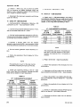
Les figures
1-5
et
1-6
illustrent la degradation
de
I'eii-
mination
du mode commun due aux differences d'impedan-
ce des sources.
La
frequence
du
signal en
mode commun
af-
fecte egalement le
taux de
rejection en
mode commun. Ge-
rwralement, au fur et k mesure
que
la frequence
du
signal
d'entr6e
augmente, le taux de
rejection
en mode commun
est
plus
difficile e maintenir.
Fig.
1-5.
Relation
axistant entre
I'impMance au point de test
et
I'im-
pMance d'entrde de
I'amplificateur. Taux de
rejection apparent
en
mode
commun du a (A)
la difference importante
entre les impedan-
ces
au
point de test et
<BI
points
de
test i
faible impedance.
Le taux de
rejection en
mode
commun en haute frequen-
ce est
Egalement fonction
de
I'impedance de
la source
du
signal car les diverses capacit^s «shunt»,
entre la
source
et
I'entree doivent se charger et se decharger k travers cette
im-
pedance.
French
1-6
@
SEP
1980

Instructions
d'utilisation
-
AM
502
Des
causes
ext6rieures
telles
que
les
champs
magnetiques
peuvent
egalement
d6grader
les
performances,
particuliere-
ment
lorsque
Ton
mesure
des
signaux
k
bas
niveau.
L'inter-
f^rence
magnetique
peut
etre
diminu6e
en
utilisant
des
liai-
sons
identiques
pour
les deux
entrees.
Torsader
les
deux
fils
ensemble
sur la
plus
grande
longueur
possible.
Des
mesures
en
basse
frequence
peuvent
etre
amelior^es
de
maniere
simi-
laire
en
utilisant
un
cable
blinde
comportant
une
paire de
conducteurs
torsades.
Fig.
1-6.
Circuit
d'entree
simplifie
et
tableau
indiquant
la
variation du
TRMC
apport#
par
des
sondes 10X
dont
la
precision
est
inftrieure
a
1, 2,
3
%
(avec des
resistances
d'entrie de
1
MS2).
@
SEP
1980
French
1-7

Kapitel 1
-
AM
502
BEDIENUNGS-
ANLEITUNG
einfOhrung
Beschreibung
Der AM 502 ist
ein
gleichspannungsgekoppelterDiffe-
renzverstarker
mit
sehr guter GleichtaktunterdrQckung
und
hoherVerstarkungfurdie
Messung kleinerSpannun-
gen.
Eine
Gleichspannungsoffseteinstellung
arbeitet
bis
zu 1
V, wodurch
gleichspannungsunterlegte Signale mit
geringem
Pegei und
niedriger Frequenz, ohne die durch
Wechselspannungskopplung
auftretenden
DSmpfun-
gen,
verstarkt werden
konnen. Oberfrontseitige Schalter
lassen
sich
verschiedene obere und untere Grenzfre-
quenzen (-3dB)
wahien, wodurch der AM
502
an ver-
schiedene
MeBprobiemeangepaBt
werden kann. Die Ein-
und
Ausgangssignale
sind sowohl frontseitig, als auch an
der
ruckseitigenKontaktIeisteabnehmbar.Uber eine Sig-
nailampe werden Ubersteuerungszustande
-
wie
zu
hohes
Eingangssignal, zu hohe
Verstarkung
Oder zu
groBer Offset
-
angezeigt.
Die Eingangsimpedanz beim AM 502 betragt 1 MQII
47
pF.
Durch Entfernen einer Brucke laBt sich
die
Ein-
gangsimpedanz auf
200
MQ steigern.
Ein Uberiastschutz erfoigt duch
Sicherungen
im Ein-
gangsbereich, die bei zu
hohem StromfluB im Obersteue-
rungsfaii unterbrechen.
Die bei verschiedenen gewahiten Verstarkungen auf-
tretende Verschiebung in der Gleichspannungsbalance
iaBt sich durch einfrontseitiges Potentiometer einstelien.
Mit den Gieichspannungsoffseteinstellreglern
(grob
und fein) ist am Eingang eine Potentiaidifferenz von ±1
V
einstelibar,
die die' interne Verstarker-Vorspannung
beeinfiuBt. FurdieseEinsteliung
istderSchaiterderunte-
ren
Grenzfrequenzwahl in die Position
DC-OFFSET zu
bringen.
DerWahischalterfurdieobereGrenzfrequenzdientzur
Reduzierung der Bandbreite am oberen Bereich,
urn
bei
der Verarbeitung
von niedrigen Frequenzen einen guten
Stbrspannungsabstand
zu
erhalten.
Die untere Grenzfre-
quenzwahi
gestattet eine
Verringerung der
Bandbreite
am unteren Bereich.
Bei Anwendung der Wechselstromankopplung
durch
einen Kondensator, verhindert eine Voraufladevorrich-
tung
am
AM
502
VerschiebestrPme in dem Kondensator,
die eine Beschadigung
des
Testobjektes hervorrufen
konnten.
Ein-
und Ausbau
VORSfCHT
Vor dem Einsetzen
des AM 502 in eine Vorsorgungs-
einheit, ist diese
unbedingt auszuschalten,
da
durch
die hohe Stromentnahme des AM
502
evti. Schaden
an
der
Schaltung
auftreten
konnten. Es ist
ebenfails
vor
der Entnahme des AM
502
empfehlenswert, die
Versorgungseinheit
abzuschalten.
Beziehen
Sie
sich auf
Abb.
1-1
unduberpriifen Sie, ob
die Plastikisolierstege auf der Steckverbindungs-
leiste
in
der gewahiten
Versorgungseinheit mit den
Ausschnitten aus
der Platinenkontaktieiste des
AM 502
ubereinstimmen.
Setzen Sie nun das Chassis des AM 502 in die obere
und untere Fuhrung
des
gewahiten
Faches
und schieben
es
mit dem nbtigen Druck soweit
ein,
bis die ruckseitige
Steckverbindungsieiste einrastet.
Zum Herausnehmen
des
AM
502
ziehen Sie die Entrie-
gelungskiinke
an der
linken unteren
Ecke des
Einschu-
bes,
bis sich die riickseitige Steckverbindung I6st.
Bedienungselemente und Steckverbindungen
Beziehen
Sie sich
auf Abb.
1-2.
DerAM
502
ist bei Liefe-
rung kalibriert und gebauchsfertig. BevorSie jedoch
das
Gerat
bedienen, sollten
Sie
sich mit den Funktionen
der
Bedienungseiemente vertraut machen. Zum Einschaiten
des AM 502 ist
der Netzschalter an
der
Versorgungsein-
heit
zu
ziehen, wonach am AM
502
die Netz-Anzeigeiam-
pe ieuchtet.
BEDIENUNGSHINWEiSE
Uberhitzung
Der
AM 502 ist fur einen Umgebungstemperaturbe-
reich von
0°C
bis -F50°C konzipiert. Arbeiten
jedoch in
einer Versorgungseinheit
mehrere Einschube Oder befin-
den sich in der Nahe weitere hitzeentwickeinde
Gerate,
so
kann die innere Temperatur den zuiassigen Bereich
uberschreiten
und in
der Versorgungseinheit einen
Uber-
temperaturschaiter auslosen. Beziehen
Sie
sich daher
fur weitere Informationen
auf die Bedienungsanieitung
der verwendeten Versorgungseinheit.
@
SEP 1980
German
1-1

Bedienungsanleitung
-
AM 502
Eingange
Wird
in den AM 502
ein Signal
mit hoher
Amplitude, ge-
ringer
Frequenz und
geringer
Quellenimpedanz
einge-
speist, so
kann das
mit
ungeschirmten
Verbindungska-
beln erfolgen.
Fehit
jedoch eine der
obengenannten
Be-
dingungen, so
mu6 abgeschirmtes
Kabel
verwendet
wer-
den.
Es
ist dabei
auf mdglichst
kurze
Kabelverbindungen
zu
achten.
Wird eine
MeBung
im
Eintaktbetrieb
vorgenommen
(konventionelle
Betriebsart), so
muB eine
Masseverbin-
dung
zwischen
dem Testobjekt
und
dem
AM 502
herge-
stellt werden.
Das kann
ubiicherweise
uber die
Abschir-
mung eines
Koaxialkabels
erfolgen. Der
nichtbenutzte
Eingang
des
AM
502
ist mit dem
mit GND
bezeichneten
Schalter auf
Massepotential zu
legen.
In manchen Fallen ist bei Differenzbetrieb keine Mas-
severbindung erforderlich,
wobei auch keine Masse-
schleifenstrdme auftreten
kOnnen.
Beachten Sie die
geanderten
kapazitiven
Belastungen
desTestobjektesbeiderVerwendung
langererAnschluB-
kabel. Die
Eingangsimpedanz des
AM 502 betragt
1
MQIl
47
pF.
Durch Verwendung eines
Koaxialkabels
von
ca. 70 cm
Lange
erhdht sich die
Parallelkapazitat
urn
ca.
60
pF, was in
manchen Fallen zu
hoch sein
kann.
Es
ist
dann
ein Kabel mit
hOherer
Impedanz Oder ein Teilertast-
kopf
zu
verwenden.
Tastkopfe
Teilertastkdpfe
verringern
die
kapazitive
Belastung
des Testobjektes und
enweitern den Eingangsspan-
nungsbereich des AM 502 zu
hdheren Spannungen
hin.
In
Anwendungsfailen,
wo eine
hohe
Eingangsimpe-
danz
bei geringster kapazitiver Belastung
der Signalquel-
le jedoch ohne
Signalabschwachung
erforderlich ist, ist
ein FET-Tastkopf Oder die
Hochimpedanzvorrichtung
am
AM
502 zu
verwenden. Fur weitere Informationen uber
Tastkdpfe wenden Sie sich
bittean IhreTektronix-Vertre-
tung.
Hochimpedanz-Eingang
Dm
die
Eingangsimpedanz des
AM
502
auf
>200
MQ
zu
steigern,
ist der Stecker
P
40
(siehe Abb. 3-1) zu entfer-
nen und der
Teller in die
Betriebsart NORM zu bringen.
In
diesem Fall ist
die
Signalquellenimpedanz
von
groBer
Be-
.
deutung. So
erzeugt z. B.
ein Gatestrom
von
100
pA
durch
10 MQ
eine
Offset-Spannung
von 1 mV. Bei der
Messung
von
geringen Spannungen
kann
diese Offsetspannung
zu
bedeutenden Fehlern fuhren.
Eingangsiiberiastung
Vor
der Messung
nichtbekannter
Gleichspannungen
ist die
-i-
100
Taste zu
betStigen und
der Verstarkungs-
schalter GAIN
in die Position 100 zu
stellen.
Die
Einstel-
lung der
Verstarkung
ist
zu
steigern und
schlieBlich
die
-5-
100
Taste zu
Idsen, bis ein
verwertbares Ausgangssig-
nal
am AM 502 vorliegt.
Bei Ubersteuerung des Eingangs
verursachen
hOhere
Eingangsstrdme ein Auslosen
der
Schutzsicherungen.
German
1-2
@
SEP 1980
La page est en cours de chargement...
La page est en cours de chargement...
La page est en cours de chargement...
La page est en cours de chargement...
La page est en cours de chargement...
La page est en cours de chargement...
La page est en cours de chargement...
La page est en cours de chargement...
La page est en cours de chargement...
La page est en cours de chargement...
La page est en cours de chargement...
La page est en cours de chargement...
La page est en cours de chargement...
La page est en cours de chargement...
La page est en cours de chargement...
La page est en cours de chargement...
La page est en cours de chargement...
La page est en cours de chargement...
La page est en cours de chargement...
La page est en cours de chargement...
La page est en cours de chargement...
La page est en cours de chargement...
La page est en cours de chargement...
La page est en cours de chargement...
La page est en cours de chargement...
La page est en cours de chargement...
La page est en cours de chargement...
La page est en cours de chargement...
La page est en cours de chargement...
La page est en cours de chargement...
La page est en cours de chargement...
La page est en cours de chargement...
La page est en cours de chargement...
La page est en cours de chargement...
La page est en cours de chargement...
La page est en cours de chargement...
La page est en cours de chargement...
La page est en cours de chargement...
La page est en cours de chargement...
La page est en cours de chargement...
La page est en cours de chargement...
La page est en cours de chargement...
La page est en cours de chargement...
La page est en cours de chargement...
La page est en cours de chargement...
La page est en cours de chargement...
La page est en cours de chargement...
La page est en cours de chargement...
La page est en cours de chargement...
La page est en cours de chargement...
La page est en cours de chargement...
La page est en cours de chargement...
La page est en cours de chargement...
La page est en cours de chargement...
La page est en cours de chargement...
La page est en cours de chargement...
La page est en cours de chargement...
La page est en cours de chargement...
La page est en cours de chargement...
La page est en cours de chargement...
La page est en cours de chargement...
La page est en cours de chargement...
La page est en cours de chargement...
La page est en cours de chargement...
La page est en cours de chargement...
-
 1
1
-
 2
2
-
 3
3
-
 4
4
-
 5
5
-
 6
6
-
 7
7
-
 8
8
-
 9
9
-
 10
10
-
 11
11
-
 12
12
-
 13
13
-
 14
14
-
 15
15
-
 16
16
-
 17
17
-
 18
18
-
 19
19
-
 20
20
-
 21
21
-
 22
22
-
 23
23
-
 24
24
-
 25
25
-
 26
26
-
 27
27
-
 28
28
-
 29
29
-
 30
30
-
 31
31
-
 32
32
-
 33
33
-
 34
34
-
 35
35
-
 36
36
-
 37
37
-
 38
38
-
 39
39
-
 40
40
-
 41
41
-
 42
42
-
 43
43
-
 44
44
-
 45
45
-
 46
46
-
 47
47
-
 48
48
-
 49
49
-
 50
50
-
 51
51
-
 52
52
-
 53
53
-
 54
54
-
 55
55
-
 56
56
-
 57
57
-
 58
58
-
 59
59
-
 60
60
-
 61
61
-
 62
62
-
 63
63
-
 64
64
-
 65
65
-
 66
66
-
 67
67
-
 68
68
-
 69
69
-
 70
70
-
 71
71
-
 72
72
-
 73
73
-
 74
74
-
 75
75
-
 76
76
-
 77
77
-
 78
78
-
 79
79
-
 80
80
-
 81
81
-
 82
82
-
 83
83
-
 84
84
-
 85
85


dans d''autres langues
- English: Tektronix AM 502 User manual
Documents connexes
-
Tektronix DC 504 Manuel utilisateur
-
-
-
-
-
Tektronix DPO4034B Le manuel du propriétaire
-
-
-
-
Tektronix 6 series Manuel utilisateur
Autres documents
-
Strong SRT L801 Manuel utilisateur
-
 METEX MS-9160 Le manuel du propriétaire
-
Altec 1612A SIGNAL PROCESSING Manuel utilisateur
-
Amprobe FG2C-UA & FG3C-UA Function Generators Manuel utilisateur
-
Wavetek 2C/3C Mode d'emploi
-
Megger ME-DLRO10B Le manuel du propriétaire
-
-
Premier ctv-2641sr Manuel utilisateur
-
 Metcal MFR-1300 Series Mode d'emploi
-
HP 55330M Manuel utilisateur

