
HS8
Powered Subwoofer
Enclosure
Owner’s Manual | English
Manual del Propietario | Español
SUBWOOFER AUTOAMPLIFICADO
Benutzerhandbuch | Deutsch
AKTIVSUBWOOFER GEHÄUSE
Manuel d’utilisation | Française
CAISSON DE GRAVES ACTIF
2011 Hideaway Rev N.indd 12011 Hideaway Rev N.indd 1 5/30/2017 1:55:15 PM5/30/2017 1:55:15 PM

2
Hideaway™
POWERED SUBWOOFER
ENCLOSURE Owner’s Manual
INSTALLATION
Mounting: Choose a structurally sound location to mount your KICKER powered subwoofer enclosure. Carefully
check the areas where the mounting straps will be placed. Make sure the mounting screws will not puncture
the gas tank/brake lines/wiring or interfere with any mechanical parts on the underside of the mounting surface.
Choose a location that allows at least 4” (10cm) of open ventilation for the amplifi er. If possible, mount the
enclosure in the climate-controlled passenger compartment.
Authorized KICKER Dealer:
Purchase Date:
Model Number:
Serial Number:
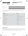
Model: HS8
Subwoofer | inches [cm] 8” [20]
RMS power @14.4V | ≤ 1% THD+N [10% THD+N] 125W [150W]
Frequency Response 25Hz–120Hz
Crossover 12dB/octave Lowpass 50–120Hz;
24dB/octave Highpass @ 25Hz
Phase Switch 0° / 180°
Input Sensitivity Low Level: 125mV–5V
High Level: 250mV–10V
KickEQ bass boost Variable to +6dB @ 40Hz
Remote bass Included
Net weight | lbs. [kg] 11.4 [5.2]
Height | inches [mm] 3 1/8” [79]
Width | inches [mm] 9 3/8” [238]
Depth | inches [mm] 13 7/8” [352]
MODEL: HS8
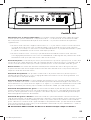
The ultra-compact KICKER Hideaway™ Enclosure offers the quickest and easiest way to add a subwoofer to
your vehicle, providing signature KICKER bass in an unprecedentedly small enclosure. This system has been
meticulously fi ne-tuned by KICKER engineers to deliver astounding performance and sound without the time-
consuming setup required for a typical amp-sub upgrade.
2011 Hideaway Rev N.indd 22011 Hideaway Rev N.indd 2 5/30/2017 1:55:35 PM5/30/2017 1:55:35 PM

3
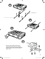
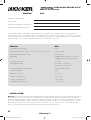
1
2
3
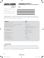
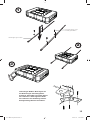
included screws
and washers
mounting straps
Bracket mounting: Mount the brackets
to the bottom of the enclosure using the
supplied smaller screws. Securely attach the
enclosure to the vehicle with the supplied
larger screws.
OR
2011 Hideaway Rev N.indd 32011 Hideaway Rev N.indd 3 5/30/2017 1:55:36 PM5/30/2017 1:55:36 PM

4
Hideaway™
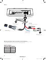
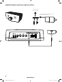
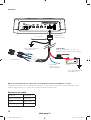
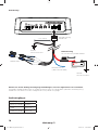
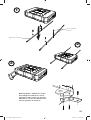
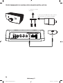
Wiring:
12V
quick-connect
harness audio inputs:
White Left +
White/Black Left –
Grey Right +
Grey/Black Right –
remote turn-on
see next page
battery
bare metal
chassis ground
bare metal
chassis ground
≤ 24” [60cm]
quick-connect
harness
15A fuse
≤18” [45cm] from positive
battery terminal
Observe the polarity of input connections to avoid signal loss.
Use the KICKER KISL for source units with RCA outputs or splice the quick-connect
harness leads directly to your source unit’s speaker-level outputs.
KICKER KISL
(sold separately)
2011 Hideaway Rev N.indd 42011 Hideaway Rev N.indd 4 5/30/2017 1:55:36 PM5/30/2017 1:55:36 PM

5
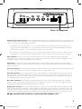
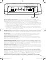
Fuse 10 Amperes
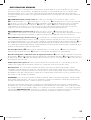
Automatic Turn-On Selection: KICKER powered enclosures offer two different automatic turn-on modes that
can be selected on the side panel; +12V and DC Offset. Using the DC Offset mode causes the REM terminal to
have +12V out for turning on additional amplifi ers.
• Remote Turn-On: Set the switch to +12V to use the remote turn-on lead from your source unit. Run 18
gauge wire from the Remote Turn-On Lead on your source unit to the terminal labeled REM on the quick-
connect power harness. This is the preferred automatic turn-on method.
• DC Offset Turn-On: If Remote Turn-On is not an option, the next best setting is DC Offset. The DC Offset
mode detects a DC offset from the HI-Level speaker outputs when the source unit has been turned on.
Phase Switch: The phase switch lets you invert the phase of the signal played through your powered
subwoofer. This is useful if the speakers in your system are out of phase with the subwoofer. Toggle this switch
to fi nd the position that gives you the best bass response.
Input Level: The inputs on KICKER powered enclosures are capable of receiving either Hi (speaker-level) or
Low-level (RCA) signals from your source unit. Set the Input Level switch on the side panel to match the outputs
of your source unit.
Crossover Control: The variable crossover on the side panel allows you to adjust the crossover frequency from
50–120Hz. The setting for this control is subjective; 80Hz is a good place to start.
Input Gain Control: The input gain control is not a volume control. It matches the output of the source unit to
the input level of the powered enclosure’s amplifi er. Turn the source unit up to about 3/4 volume (if the source
unit goes to 30, turn it to 25). Next, slowly turn the gain on the powered enclosure up (clockwise) until you can
hear audible distortion, then turn it down a little.
Bass Boost Control: The variable bass boost control on the side panel is designed to give you increased
output (0–6dB) at 40 Hz. The setting for this control is subjective. If you turn it up, you must readjust the input
gain control to avoid clipping the powered enclosure’s amplifi er.
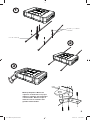
Remote Bass Control: With the included remote bass control, you have the ability to control the output level
of your powered enclosure remotely. When plugged into the enclosure, the remote bass control bypasses and
takes the place of the gain control on the side panel. To mount the remote bass level control, simply screw the
metal bracket to the chosen location, then slide the housing onto the bracket until it snaps into place. Run the
cable from the controller to the “Remote Bass” jack on your powered enclosure’s side panel.
DO NOT disconnect the remote bass control when the amplifi er is on!
2011 Hideaway Rev N.indd 52011 Hideaway Rev N.indd 5 5/30/2017 1:55:36 PM5/30/2017 1:55:36 PM

6
Hideaway™
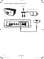
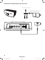
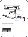
REMOTE BASS CONTROL INSTALLATION
1. mount the
metal bracket
2. slide the housing until it snaps
into the metal bracket
2011 Hideaway Rev N.indd 62011 Hideaway Rev N.indd 6 5/30/2017 1:55:36 PM5/30/2017 1:55:36 PM

7
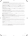
TROUBLESHOOTING
If your amplifi er does not appear to be working, check the obvious things fi rst such as blown fuses, poor or
incorrect wiring connections, incorrect setting of crossover and gain controls, etc. There is a dual-stage PWR/
PRT LED on side panel of your powered enclosure denoting the power state of the amplifi er. When the LED is
blue, this indicates the powered enclosure is turned on and its amplifi er is functioning properly.
PWR/PRT LED off, no output? With a Volt Ohm Meter (VOM) check the following:
+12 volt power terminal
(should read +12V to +16V)
Remote turn-on terminal (should read +12V to +16V)
Check for reversed
power and ground connections.
Ground terminal, for proper conductivity.
Check for blown fuses.
Check the AUTO TURN-ON switch setting. Check for a DC offset between a speaker lead and ground if using
DC-OFFSET mode.
PWR/PRT LED blue, no output? Check the following:
audio input connections
Substitute source unit
with a “known” good source unit.
Check for a signal in the audio cable feeding the powered enclosure with
the VOM meter set to measure “AC” voltage.
PWR/PRT LED red, no output?
Amplifi er shuts down only while vehicle is running = voltage protection
circuitry is engaged. Voltage to the amplifi er is not within the 10–16 volt operating range. Have the vehicle’s
charging and electrical system inspected.
A red PWR/PRT LED may also indicate low battery voltage. Check
all the connections in your vehicle’s charging system. It may be necessary to replace or charge your vehicle’s
battery or replace your vehicle’s alternator.
No or low output?
Check the balance control on source unit
Check the amplifi er input connections.
Check the polarity of the input signal connections.
Alternator noise-whining sound with engine’s RPM?
Check for damaged RCA (or speaker input) cable
Check the routing of RCA (or speaker input) cable through your vehicle—move it away from power cables.
Check the source unit for proper grounding
Check the gain settings and turn them down if they are set too
high
Check ground wire connections and make sure they are tightly connected.
Reduced bass response? Flip the phase switch to the opposite position; if the bass improves, your speakers
were out of phase with the subwoofer.
Ground Noise? KICKER amplifi ers are engineered to be fully compatible with all manufacturers’ head units.
Some head units may require additional grounding to prevent noise from entering the audio signal. If you are
experiencing this problem with your head unit, in most cases running a ground wire from the RCA outputs on the
head unit to the chassis will remedy this issue. If you still have problems, run your input signal at speaker-level
from your source unit to the amplifi er.
CAUTION: When jump starting the vehicle, be sure that connections made with jumper cables are correct.
Improper connections can result in blown amplifi er fuses as well as the failure of other critical systems in the
vehicle.
If you have more questions about the installation or operation of your new KICKER product, see the Authorized
KICKER Dealer where you made your purchase. For more advice on installation, click on the SUPPORT section
on the KICKER homepage, www.kicker.com. Please E-mail support@kicker.com or call Technical Services
(405) 624-8583 for unanswered or specifi c questions.
2011 Hideaway Rev N.indd 72011 Hideaway Rev N.indd 7 5/30/2017 1:55:37 PM5/30/2017 1:55:37 PM

8
Hideaway™
SUBWOOFER
AUTOAMPLIFICADO Manual del Propietario
INSTALACIÓN
Montaje: Elija una ubicación estructuralmente sólida para montar el gabinete de su subwoofer energizado
KICKER. Revise cuidadosamente las áreas en donde se colocarán las tiras de montaje. Asegúrese de que los
tornillos de montaje no perforen el tanque de gasolina, las líneas de los frenos ni el cableado, y que no interfi eran
con las partes mecánicas que se encuentran en la parte inferior de la superfi cie de montaje. Elija una ubicación
que deje al menos 10 cm (4”) de ventilación abierta para el amplifi cador. Si es posible, monte el gabinete en el
compartimiento para pasajeros que cuente con control del clima.
MODELO: HS8
Los gabinetes energizados y ahorradores de espacio KICKER Hideaway™ ofrecen la forma más rápida y
sencilla de agregarle un subwoofer a su vehículo. Estos sistemas han sido diseñados meticulosamente por los
ingenieros de KICKER para proporcionar un desempeño y un sonido asombrosos sin la lenta confi guración que
requiere una actualización de amplifi cador-subwoofer típica.
Distribuidor autorizado de KICKER:
Fecha de compra:
Número de modelo del amplifi cador:
Número de serie del amplifi cador:
Modelo: HS8
Subwoofer | pulgadas [cm] 8 [20]
Potencia RMS @ 14.4V | ≤ 1% THD+N [10% THD+N] 125W [150W]
Respuesta de Frecuencias ± 1dB 25Hz–120Hz
Filtro de Cruce (Crossover) 12dB/octava Pasobajo 50–120Hz;
24dB/octava Pasoalto @ 25Hz
Interruptor de Fase 0° / 180°
Sensibilidad de Entrada Bajo Nivel: 125mV–5V
Alto Nivel: 250mV–10V
KickEQ Refuerzo de Bajos Variable a +6dB @ 40Hz
Remoto de Bajos Incluido
Peso neto | lbs. [kg] 11.4 [5.2]
Altura | pulgadas [mm] 3 1/8” [79]
Ancho | pulgadas [mm] 9 3/8” [238]
Profundidad pulgadas [mm] 13 7/8” [352]
2011 Hideaway Rev N.indd 82011 Hideaway Rev N.indd 8 5/30/2017 1:55:37 PM5/30/2017 1:55:37 PM

9
1
2
3
tornillos y arandelas
incluidos
tiras de montaje
Montaje Soportes: Monte los
soportes al fondo de la caja que
utiliza los tornillos más pequeños
suministrados. Monte la caja al
vehículo con los tornillos más
grande suministrados.
2011 Hideaway Rev N.indd 92011 Hideaway Rev N.indd 9 5/30/2017 1:55:37 PM5/30/2017 1:55:37 PM

10
Hideaway™
Cableado:
12V
Entradas de audio
Blanca Izquierda +
Blanca/Negra Izquierda –
Gris Derecha +
Gris/Negra Derecha –
Encendido
remoto, vea la
página siguiente
batería
Tierra directamente al
metal del chasis
Tierra directamente al
metal del chasis
KICKER KISL
≤ 24” [60cm]
Conector de
conexión rápida
15A fusible
deje un espacio de ≤ 45 cm (18”)
desde la terminal positiva de la batería
Observe la polaridad de las conexiones de entrada para evitar la pérdida de la señal.
Utilice el KISL KICKER para las unidades de fuente con salidas RCA o empalme el arnés de conexión rápida
conduce directamente a las salidas de la unidad fuente de nivel de altavoz.
2011 Hideaway Rev N.indd 102011 Hideaway Rev N.indd 10 5/30/2017 1:55:37 PM5/30/2017 1:55:37 PM

11
Selección de encendido automático: los gabinetes con la tecnología de KICKER ofrecen dos modos
distintos de encendido automático que se pueden seleccionar en el panel lateral: +12V y desvío de CD. Usar el
modo desvío de CD hace que la terminal REM tenga +12V para encender amplifi cadores adicionales.
• Encendido remoto: coloque el interruptor en la posición +12V para emplear el cable de encendido remoto
desde la unidad fuente. Conecte un cable calibre 18 desde la salida de Cable de encendido remoto de la
unidad fuente hasta la terminal etiquetada como REM en el cable preformado de conexión rápida. Este es
el método preferido para el encendido automático.
• Encendido con desvío de CD: Si el encendido remoto no es una opción, la siguiente mejor confi guración
es desvío de CD. El modo de desvío de CD detecta un desvío de CD desde las salidas de alto nivel de las
bocinas cuando la unidad fuente ha sido encendida.
Interruptor de fase: El interruptor de fase le permite invertir la fase de la señal que se reproduce a través del
subwoofer con alimentación eléctrica. Esto es útil cuando las bocinas de su sistema están fuera de fase con el
subwoofer. Mueva el interruptor para encontrar la posición que le proporcionará la mejor respuesta de los bajos.
Nivel de entrada: Las entradas en los gabinetes con tecnología de KICKER tienen capacidad para recibir
señales de alto o de bajo nivel desde la unidad fuente. Confi gure el interruptor del nivel de entrada que se
encuentra en el panel lateral para que coincida con las salidas de su unidad fuente.
Control de fi ltro de cruce (Crossover): El fi ltro de cruce variable que se encuentra en el panel lateral le
permite ajustar la frecuencia del fi ltro de cruce de 50 a 120 Hz. La confi guración para este control es subjetiva;
pero 80 Hz es un buen lugar para comenzar.
Control de ganancia de entrada: el control de ganancia de entrada no es un control de volumen. Iguala la
salida de la unidad fuente con el nivel de entrada del amplifi cador con alimentación eléctrica. Encienda la unidad
fuente hasta 3/4 del volumen (si la unidad llega a 30, enciéndala a 25). Después, lentamente gire hacia arriba el
control de ganancia del gabinete con alimentación eléctrica (en el sentido de las manecillas del reloj) hasta que
pueda escuchar una distorsión, y después gire el control un poco hacia abajo.
Control de aumento de los bajos: El control variable de aumento de los bajos que se encuentra en el panel
lateral está diseñado para proporcionarle una salida mejorada (0–6dB) a 40 Hz. La confi guración de este control
es subjetiva. Si sube el nivel, deberá volver a ajustar el control de ganancia de entrada para evitar el recorte de la
señal del amplifi cador del gabinete con alimentación eléctrica.
Control remoto de los bajos: Con el control remoto de los bajos que se incluye, usted tiene la posibilidad
de controlar el nivel de salida de su gabinete de forma remota. Cuando está conectado al gabinete, el control
remoto de los bajos omite y reemplaza al control de ganancia del panel lateral. Para montar el control remoto del
nivel de bajos, simplemente atornille el soporte metálico en la ubicación deseada, después deslice el gabinete
en el soporte hasta que quede puesto en su lugar. Coloque un cable desde el controlador hasta el conector
marcado como “Remote Bass” (bajo remoto) que se encuentra en el panel lateral del gabinete.
¡NO desconecte el control remoto de los bajos cuando el amplifi cador esté encendido!
Fusible 10A
2011 Hideaway Rev N.indd 112011 Hideaway Rev N.indd 11 5/30/2017 1:55:37 PM5/30/2017 1:55:37 PM

12
Hideaway™
CONTROL REMOTO DE BAJOS INSTALACIÓN
1. monte el
soporte de metal
2. deslice el alojamiento hasta que
encaje en el soporte de metal
2011 Hideaway Rev N.indd 122011 Hideaway Rev N.indd 12 5/30/2017 1:55:37 PM5/30/2017 1:55:37 PM

13
SOLUCIÓN DE PROBLEMAS
Si parece que su amplifi cador no está funcionando, revise primero las cosas obvias como fusibles fundidos,
conexiones malas o incorrectas de los cables, confi guración incorrecta de los controles de fi ltro de cruce y de
ganancia, etc. En el panel lateral del gabinete se encuentra un LED PWR/PRT de doble etapa que indica el
estado de la energía del amplifi cador. Cuando el LED está en azul, indica que el gabinete está encendido y que
el amplifi cador funciona de manera apropiada.
¿El LED PWR/PRT está apagado y no hay salida? Con un voltímetro (VOM) revise lo siguiente:
La
terminal de corriente de +12 voltios (deberá decir +12V a +16V).
Encienda la terminal en forma remota
(deberá indicar +12V a +16V).
Compruebe que las conexiones de energía y de tierra no estén invertidas
Terminal a tierra para una conductividad apropiada
Revise que no haya fusibles fundidos.
Revise la
confi guración de AUTO TURN-ON (Encendido automático). Busque un desfase de corriente directa entre el
cable de la bocina y la conexión a tierra si utiliza el modo DC-OFFSET (Desfase de corriente directa).
¿El LED PWR/PRT está en azul y no hay salida? Revise lo siguiente:
las conexiones de entrada de
audio
Sustituya la unidad fuente con una unidad fuente que funcione.
Revise que el cable de sonido que
alimenta al gabinete tenga señal con el voltímetro confi gurado para medir voltaje “CA.”
¿El LED PWR/PRT está en rojo y no hay salida?
El amplifi cador se apaga sólo mientras el vehículo está
encendido = los circuitos de protección de voltaje están activados. El voltaje que llega al amplifi cador no está
dentro del rango de operación de 10 a 16 voltios. Haga que revisen el sistema de carga y eléctrico del vehículo.
Un LED PWR/PRT rojo también podría indicar un bajo voltaje de la batería. Revise todas las conexiones del
sistema de carga de su vehículo. Tal vez tendrá que reemplazar o recargar la batería de su vehículo o reemplazar
el alternador del vehículo.
¿No hay salida o la salida es muy baja?
Compruebe el control de balance en la unidad fuente.
Compruebe las conexiones de entrada y salida de las bocinas.
Compruebe la polaridad de las conexiones
de la señal de entrada.
¿El alternador emite un sonido o hay un sonido de silbido cuando el motor se revoluciona?
Compruebe que el cable RCA (o la entrada de las bocinas) no esté dañado.
Compruebe que el cable
RCA (o la entrada de las bocinas) esté conectado en el lugar apropiado.
Compruebe que la conexión a
tierra de la unidad fuente sea apropiada.
Compruebe las confi guraciones de ganancia y baje el nivel si está
demasiado alto.
Compruebe las conexiones de cable a tierra y asegúrese de que estén bien conectados.
¿La respuesta de los bajos es reducida? Coloque el interruptor de fase en la posición opuesta; si los bajos
mejoran, sus bocinas estaban fuera de fase con el subwoofer.
¿La conexión a tierra hace ruido? Los amplifi cadores KICKER están diseñados para ser totalmente
compatibles con las unidades principales de todos los fabricantes. Algunas unidades principales pueden
requerir conexión a tierra adicional para evitar que se escuche ruido en la señal de audio. Si usted tiene este
problema con su unidad principal, en la mayoría de los casos colocar un cable a tierra desde las salidas RCA de
la unidad principal hasta el chasis solucionará este problema.
PRECAUCIÓN: Cuando arranque el vehículo haciendo un puente, asegúrese de que las conexiones de los
cables para el puente sean correctas. Las conexiones mal colocadas pueden ocasionar que los fusibles del
amplifi cador se fundan y que otros sistemas críticos del vehículo fallen.
Si tiene más preguntas acerca de la instalación o de la operación de su nuevo producto KICKER, consulte a su
Distribuidor de KICKER autorizado en donde realizó la compra. Para obtener más consejos sobre la instalación,
haga clic en la sección SOPORTE de la página principal de KICKER, www.kicker.com. Por favor envíe un
correo electrónico a support@kicker.com o llame al Servicio Técnico al (405) 624-8583 si aún tiene preguntas o
si sus preguntas son más específi cas.
2011 Hideaway Rev N.indd 132011 Hideaway Rev N.indd 13 5/30/2017 1:55:38 PM5/30/2017 1:55:38 PM

14
Hideaway™
AKTIVSUBWOOFER
Benutzerhandbuch
INSTALLATION
Einbau: Wählen Sie einen geeigneten Platz für den Einbau Ihres KICKER Subwoofer-Gehäuses. Kontrollieren Sie
genau, wo die Sie die Montagebügel anbringen wollen. Vergewissern Sie sich, dass die Einbauschrauben nicht
den Kraftstofftank, die Bremsleitungen oder Drähte beschädigen oder die mechanischen Teile auf der Unterseite
der Einbaufl äche beeinträchtigen. Wählen Sie einen Einbauort mit mindestens 10 cm ausreichender Belüftung für
den Verstärker. Wenn möglich, montieren Sie das Gehäuse in der klimatisierten Fahrgastzelle.
MODELL: HS8
Die platzsparenden KICKER Hideaway™ Powered Enclosures können schnell und einfach in Ihrem Fahrzeug
installiert werden. Diese Systeme wurden von den KICKER-Ingenieuren noch weiter verbessert, um eine
hervorragende Leistung und einen unübertroffenen Sound sicherzustellen, ohne die zeitaufwändige Montage für
herkömmliche Verstärker.
Autorisierter KICKER-Händler:
Kaufdatum:
Verstärker-Modellnummer:
Verstärker-Seriennummer:
Modell: HS8
Subwoofer | zoll [cm] 8 [20]
RMS-Leistung @ 14,4V | ≤ 1% THD+N [≤ 10% THD+N] 125W (150W)
Frequenzgang ± 1dB 25Hz–120Hz
Crossover 12dB/oktave Tiefpass 50–120Hz;
24dB/oktave Hochpass @ 25Hz
Phasenschalter 0° / 180°
Eingangsempfi ndlichkeit N-Pegel: 125mV–5V
H-Pegel: 250mV–10V
KickEQ Bass Boost Variabel +6dB @ 40Hz
Remote bass Inbegriffen
Nettogewicht | lbs, [kg] 11,4 [5,2]
Höhe | zoll [mm] 3 1/8” [79]
Breite | zoll [mm] 9 3/8” [238]
Tiefe | zoll [mm] 13 7/8” [352]
2011 Hideaway Rev N.indd 142011 Hideaway Rev N.indd 14 5/30/2017 1:55:38 PM5/30/2017 1:55:38 PM

15
1
2
3
mit Schrauben und
Unterlegscheiben
Befestigungslaschen
Halterungen Einbau: Befestigen Sie
die Halterungen mit beiliegenden
kleineren Schrauben an beiden Seiten
des Gehäuses. Befestigen Sie dann
das Gehäuse zum Fahrzeug mit den
beiliegenden größeren Schrauben.
2011 Hideaway Rev N.indd 152011 Hideaway Rev N.indd 15 5/30/2017 1:55:38 PM5/30/2017 1:55:38 PM

16
Hideaway™
Verkabelung:
12V
Audioeingänge:
Weiß Links +
Weiß/Schwarz Links –
Grau Rechts +
Grau/Schwarz Rechts –
Remote Turn-On.
(siehe nächste Seite)
Schnellkupplung
Kabelbaum
Batterie
Blanker
Masse-Anschluss
KICKER KISL
Blanker
Masse-Anschluss
≤ 24” [60cm]
15A Sicherung
≤45 cm vom Pluspol der Batterie
Achten Sie auf die Polung der Eingangsverbindungen, um einen Signalverlust zu vermeiden.
Verwenden Sie die KICKER KISL für Quelle Geräte mit Cinch-Ausgänge oder Spleiß der Schnellkupplung
Kabelbaum führt direkt auf Ihrem Quellgerät die Lautsprecher-Ausgänge.
2011 Hideaway Rev N.indd 162011 Hideaway Rev N.indd 16 5/30/2017 1:55:38 PM5/30/2017 1:55:38 PM

17
Automatische Einschaltauswahl: KICKER Powered Enclosures umfassen zwei automatische Einschaltmodi,
die an der Seite ausgewählt werden können: +12V und DC Offset. Der DC Offset-modus aktiviert am REM-
Anschluss die +12V Ausgabe für das Einschalten zusätzlicher Verstärker.
• Remote Turn-On: Legen Sie den Schalter auf +12V fest, um den Remote Turn-On auf der Haupteinheit
zu verwenden. Verbinden Sie den Remote Turn-On-Anschluss an der Haupteinheit über ein 18 Gauge
Kabel mit dem REM-Anschluss am Quick-Connect-Netzanschluss. Dies ist die bevorzugte automatische
Einschaltmethode.
• DC Offset Turn-On: Wenn Remote Turn-On nicht verfügbar ist, ist die nächstbeste Einstellung DC Offset.
Der DC Offset-Modus erkennt einen DC Offset der HI-Level-Lautsprecherausgänge, wenn die Haupteinheit
eingeschaltet ist.
Phasenschalter: Mit dem Phasenschalter können Sie die Phase des Signals umkehren, das über den
Subwoofer wiedergegeben wird. Dies ist insbesondere hilfreich, wenn die Systemlautsprecher nicht mit dem
Subwoofer abgestimmt sind. Drehen Sie den Schalter in die Position, die die beste Basswiedergabe ermöglicht.
Eingangspegel: Die Eingänge an den KICKER Powered Enclosures können hohe und niedrige Signale von
der Haupteinheit empfangen. Legen Sie den Eingangspegel an der Seite fest, um diesen an die Ausgänge der
Haupteinheit anzupassen.
Crossover-Regler: Mit dem einstellbaren Crossover an der Seite können Sie die Trennfrequenz zwischen 50
bis 120 Hz anpassen. Die Einstellung für diesen Regler ist subjektiv. Ein guter Wert ist 80Hz.
Eingangslautstärkeregler: Der Eingangslautstärkeregler ist kein Lautstärkeregler. Er passt den Ausgang der
Haupteinheit an den Eingangspegel des Verstärkers des Powered Enclosures an. Stellen Sie die Haupteinheit
auf ca. drei Viertel der Lautstärke ein (wenn die Haupteinheit bis zu 30 geht, legen Sie 25 fest). Drehen Sie den
Regler am Powered Enclosure langsam im Uhrzeigersinn bis Sie eine Verzerrung hören und drehen Sie den
Regler etwas zurück.
Bass-Boost-Regler: Der einstellbare Bass-Boost-Regler an der Seite ermöglicht das Erhöhen des Ausgangs
(0–6dB) auf 40 Hz. Die Einstellung für diesen Regler ist subjektiv: Wenn Sie den Regler höher drehen, müssen
Sie den Eingangslautstärkeregler entsprechend anpassen, um das Trennen des Verstärkers des Powered
Enclosures zu verhindern.
Remote-Bassregler: Mit dem inbegriffenen Remote-Bassregler können Sie den Ausgabepegel des Powered
Enclosures per Fernbedienung steuern. Wenn Sie den Remote-Bassregler in das Gehäuse einstecken, tritt er an
die Stelle des Lautstärkereglers. Um den Remote-Bassregler zu montieren, schrauben Sie die Metallklammer an
der gewünschten Stelle an und schieben Sie das Gehäuse auf die Klammer, bis dieses einrastet. Verbinden Sie
den Controller über ein Kabel mit der „Remote Bass“-Buchse an der Seite des Powered Enclosures.
Die Fernsteuerung des Basspegels DARF NICHT getrennt werden, wenn der Verstärker
angeschaltet ist!
Sicherungen 10A
2011 Hideaway Rev N.indd 172011 Hideaway Rev N.indd 17 5/30/2017 1:55:38 PM5/30/2017 1:55:38 PM

18
Hideaway™
BASSPEGEL-FERNBEDIENUNG INSTALLATION
1. Metallhalterung befestigen
2. Schieben Sie das Gehäuse ein, bis
es in der Metallhalterung einrastet.
2011 Hideaway Rev N.indd 182011 Hideaway Rev N.indd 18 5/30/2017 1:55:38 PM5/30/2017 1:55:38 PM

19
PROBLEMBEHANDLUNG
Wenn der Verstärker nicht funktioniert, überprüfen Sie die offensichtlichen Fehlerquellen, beispielsweise
durchgebrannte Sicherungen, falsche Kabelverbindungen, unzulässige Einstellungen für Crossover und
Verstärkerregelung, usw. An der Seite des Powered Enclosures befi ndet sich eine PWR/PRT Zweiphasen-
LED, die den Energiestatus des Verstärkers anzeigt. Eine blau LED zeigt an, dass das Powered Enclosure
eingeschaltet ist und die Verstärker einwandfrei funktionieren.
PWR/PRT LED inaktiv, kein Ausgang? Überprüfen Sie mit einem Volt-Ohm-Meter (VOM) Folgendes:
+12 Den Stromanschluss (sollte +12V bis +16V sein).
Den Remote-Turn-On-Anschluss (sollte +12V bis
+16V sein).
Überprüfen Sie, ob die Strom- und Erdungsverbindung umgekehrt ist.
Den Erdungsanschluss
auf Leitfähigkeit.
Überprüfen Sie, ob Sicherungen durchgebrannt sind.
Kontrollieren Sie die Einstellung des
AUTOMATISCHEN EIN-Schalters. Kontrollieren Sie, ob zwischen dem Lautsprecheranschluss und der Erdung
Offset-Gleichspannung besteht.
PWR/PRT LED blau, kein Ausgang? Überprüfen Sie Folgendes:
Die Audioeingangsverbindungen.
Ersetzen Sie die Haupteinheit durch eine funktionierende Haupteinheit.
Überprüfen Sie mit dem VOM-
Meter, der auf Wechselspannung festgelegt ist, das Audiokabel zum Powered Enclosure auf ein Signal.
PWR/PRT LED rot, kein Ausgang?
Der Verstärker schaltet sich nur aus, wenn das Fahrzeug in Bewegung
ist = Der Spannungsschutzschalter ist eingerastet. Die Stromspannung für den Verstärker liegt nicht im
Betriebsbereich von 10 bis 16 Volt. Lassen Sie das Lade- und Elektriksystem des Fahrzeugs überprüfen.
Eine
rote PWR/PRT LED kann auch einen niedrigen Batteriestand anzeigen. Überprüfen Sie alle Verbindungen im
Ladesystem Ihres Fahrzeugs. Möglicherweise müssen Sie die Fahrzeugbatterie ersetzen oder aufl aden bzw. die
Lichtmaschine ersetzen.
Keine oder niedrige Ausgabe?
Überprüfen Sie den Balanceregler an der Haupteinheit.
Überprüfen Sie
die Verbindungen am Lautsprechereingang und -ausgang.
Kontrollieren Sie die Polung der Verbindungen des
Eingangssignals.
Die Lichtmaschine macht ein heulendes Geräusch mit der Motordrehzahl?
Überprüfen Sie, ob
das RCA-Kabel (oder der Lautsprechereingang) beschädigt ist.
Überprüfen Sie die RCA-Kabelleitung (oder
den Lautsprechereingang).
Überprüfen Sie, ob die Haupteinheit richtig geerdet ist.
Überprüfen Sie die
Verstärkereinstellungen und reduzieren Sie die Einstellungen, wenn diese zu hoch sind.
Stellen Sie sicher,
Erdungskabel sind sicher.
Reduzierte Basswiedergabe? Drehen Sie den Phasenschalter in die entgegengesetzte Richtung. Wenn sich
der Bass verbessert, waren die Lautsprecher nicht mit dem Subwoofer abgestimmt.
Eigenrauschen? Die KICKER-Verstärker sind für die vollständige Kompatibilität mit den Headunits aller
Hersteller ausgelegt. Einige Headunits erfordern möglicherweise eine zusätzliche Erdung, um Störgeräusche
im Audiosignal zu verhindern. Wenn dieses Problem mit Ihrer Headunit auftritt, ist es meistens ausreichend, ein
Erdungskabel in die RCA-Cinchbuchse an der Headunit und das Gehäuse einzustecken.
ACHTUNG: Wenn das Fahrzeug Starthilfe benötigt, stellen Sie sicher, dass das Überbrückungskabel richtig
angeschlossen ist. Ein unsachgemäß angeschlossenes Überbrückungskabel kann dazu führen, dass die
Verstärkersicherungen durchbrennen oder andere wichtige Systeme im Fahrzeug beschädigt werden.
Falls Sie weitere Fragen zur Installation oder den Betrieb Ihres neuen KICKER-Produkts haben, wenden Sie
sich an den autorisierten KICKER-Händler, bei dem Sie das Produkt gekauft haben. Weitere Informationen zur
Installation fi nden Sie im Abschnitt SUPPORT auf der KICKER-Homepage unter www.kicker.com. Senden Sie
eine E-Mail an support@kicker.com oder rufen Sie den technischen Support unter der Nummer (405) 624-8583
an, falls Sie noch weitere Fragen haben.
2011 Hideaway Rev N.indd 192011 Hideaway Rev N.indd 19 5/30/2017 1:55:39 PM5/30/2017 1:55:39 PM

20
Hideaway™
CAISSON DE GRAVES ACTIF
Manuel d’utilisation
INSTALLATION
Montage : Avant d’installer votre enceinte d’extrêmes basses KICKER, choisissez un emplacement acoustique
en termes de structure. Assurez-vous au préalable d’avoir identifi é avec précision l’endroit où les sangles de
montage seront disposées. Veillez à ce que les vis de montage ne puissent pas perforer le réservoir à essence/
les canalisations de frein/les câbles ni gêner les pièces mécaniques situées sur la face inférieure de la surface
de montage. Choisissez un emplacement laissant au moins 4” (10 cm) afi n de garantir la ventilation libre de
l’ampli. Si possible, placez l’enceinte dans le compartiment passager climatisé.
MODÈLE: HS8
Les enceintes KICKER Powered à gain de place sont le moyen le plus rapide et le plus simple d’ajouter un
caisson des basses (« subwoofer ») dans votre véhicule. Ces systèmes ont été conçus avec le plus grand soin
par les ingénieurs de chez KICKER pour assurer des performances et un son exceptionnels sans nécessiter les
réglages toujours très fastidieux indispensables lors d’une extension amp-sub.
Revendeur agréé KICKER :
Date d’achat :
Numéro de modèle de l’amplifi cateur :
Numéro de série de l’amplifi cateur :
Modèle: HS8
Subwoofer | pouces [cm] 8 [20]
Puissance Effi cace @ 14.4V | ≤ 1% THD+N [≤ 10% THD+N] 125W [150W]
Réponse en Fréquence ± 1dB 25Hz–120Hz
Répartiteur 12dB/octave Passe-bas 50–120Hz;
24dB/octave Passe-haut @ 25Hz
Inversion de Phase 0° / 180°
Sensibilité d’Entrée Bas niveau: 125mV–5V
Haut niveau: 250mV–10V
KickEQ Amplifi cation des Graves Variable +6dB @ 40Hz
Graves extérieures Inclus
Poids net | lbs. [kg] 11,4 [5,2]
Hauteur | pouces [mm] 3 1/8” [79]
Largeur | pouces [mm] 9 3/8” [238]
Profondeur | pouces [mm] 13 7/8” [352]
2011 Hideaway Rev N.indd 202011 Hideaway Rev N.indd 20 5/30/2017 1:55:39 PM5/30/2017 1:55:39 PM
La page charge ...
La page charge ...
La page charge ...
La page charge ...
La page charge ...
La page charge ...
La page charge ...
La page charge ...
-
 1
1
-
 2
2
-
 3
3
-
 4
4
-
 5
5
-
 6
6
-
 7
7
-
 8
8
-
 9
9
-
 10
10
-
 11
11
-
 12
12
-
 13
13
-
 14
14
-
 15
15
-
 16
16
-
 17
17
-
 18
18
-
 19
19
-
 20
20
-
 21
21
-
 22
22
-
 23
23
-
 24
24
-
 25
25
-
 26
26
-
 27
27
-
 28
28


Kicker 2011 Hideaway Powered Subwoofer Enclosure Le manuel du propriétaire
- Taper
- Le manuel du propriétaire
- Ce manuel convient également à
dans d''autres langues
Documents connexes
-
Kicker PTRTP Series Le manuel du propriétaire
-
Kicker ZXMRLC (ZXM Amplifier Remote Level Control) Le manuel du propriétaire
-
-
-
Kicker Hideaway HS10 Le manuel du propriétaire
-
Kicker TL7T8 Manuel utilisateur
-
Kicker 2011 Hideaway Powered Subwoofer Enclosure Le manuel du propriétaire
-
-
-