Bosch VCUNM1 Manuel utilisateur
- Catégorie
- Antennes réseau
- Taper
- Manuel utilisateur

This technical manual is intended for usage in the context of regulatory approvals (please ensure that
the correct model-name reference is used).
It does not replace a vehicle- or region-specific OEM owners or user manual.
It is the OEMs responsibility (General Motors) to ensure that all mandatory information with regulatory
relevance is made available to end-customers in the owners and user manuals.
Business name of device manufacturer:
Robert Bosch GmbH
Address:
Robert Bosch GmbH
Robert-Bosch-Platz 1
70839 Gerlingen
Germany
Brand:
Bosch
09/14/23 – v1
Vehicle Cockpit Unit (VCU)
Technical Description and Installers Manual
Model: VCUNM1

Version:
1
Date:
9/29/2023
VCU 1.0 - Technical Description and Installers Manual
Page 2
© Robert Bosch GmbH 2022. All rights reserved, also regarding any disposal, exploitation, reproduction, editing, distribution, as well as in the event of
applications for industrial property rights.
Table of Contents
1. DEVICE DESCRIPTION ....................................................................................................................... 3
2. SAFETY AND WARNING NOTES ........................................................................................................ 5
3. OPERATING MODES AND WIRELESS CHARACTERISTICS ........................................................... 6
3.1. Bluetooth ....................................................................................................................................... 6
3.2. WiFi ............................................................................................................................................... 6
4. INSTALLATION ..................................................................................................................................... 7
5. CERTIFICATION NOTICES AND REGULATORY VERBIAGE ......................................................... 10
5.1. General Notices .......................................................................................................................... 10
5.2. Additional Country Specific Requirements .................................................................................. 10
5.2.1. USA ..................................................................................................................................... 10
5.2.2. Canada ................................................................................................................................ 10

Version:
1
Date:
9/29/2023
VCU 1.0 - Technical Description and Installers Manual
Page 3
© Robert Bosch GmbH 2022. All rights reserved, also regarding any disposal, exploitation, reproduction, editing, distribution, as well as in the event of
applications for industrial property rights.
1. DEVICE DESCRIPTION
General Motors’ (“GM”) Vehicle Cockpit Unit (VCU) 1.0 is a technology upgrade for the previous
generation GM Cockpit ECU platform (“Info 3.x”).
The GM Vehicle Cockpit System (“VCS”) is responsible for the user experience in the cockpit of GM
vehicles.
The VCU, a Bosch device for GM vehicles, is a silver box solution providing interfaces to displays,
speakers, sensors and optional components of the VCS.
The VCU, provides the following capabilities:
1 Vehicle and infotainment related information to the slim-IPC, ICS, auxiliary, HVAC, and HUD
displays. This includes processing of various vehicle camera viewing streams to certain displays.
2 Audio capability that includes processing various radio broadcasts to the vehicle, voice capturing
using microphone inputs, user media playback via phone or USB, and integrating audio
enhancements (for example ANC) using microphone inputs.
3 Wi-Fi, Bluetooth, and GPS connectivity.
4 Various analog and digital I/O, including but not limited to switches, HUDs, sensors, etc.
It supports two major GM electrical vehicle architectures (called “Global B” and “CLEA”) and is offered in
two major product variants: “MID” and “HIGH”. In terms of regional support, a distinction is made between
North America (“NA”), China (“CN”) and RestOfWorld (“RoW”) configurations.
The VCU hardware is based on a two-processor approach where Qualcomm’s latest ARM-based
automotive system-on-chip (SoC) family 8195 (High) and 8155 (Mid) acts as core computing element and
Renesas Electronics' latest automotive micro-controller RH850F1KM/KH (Vehicle Interface Processor, VIP)
is used for real-time processing needs.
The VCU software architecture is mainly based on 3 run-time environments (called SW domains):
• Running on VIP:
o AUTOSAR OS as real-time processing system
• Running on SoC:
o Blackberry Hypervisor V2.x based on QNX7.x to realize a host environment and guest
environment as virtual machine
o Host: QNX7.x operating system
o Guest: Android system based on Linux kernel
The VCU can determine its geographical location:
• In the VCUNM1 the positioning information is provided by an external device, the Telematics
Module.

Version:
1
Date:
9/29/2023
VCU 1.0 - Technical Description and Installers Manual
Page 4
© Robert Bosch GmbH 2022. All rights reserved, also regarding any disposal, exploitation, reproduction, editing, distribution, as well as in the event of
applications for industrial property rights.
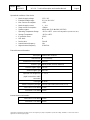
Operational conditions of the device:
• Nominal supply voltage: 13.5 V DC
• Extended voltage range: 6.0 V to 16.0 V DC
• Max. Current consumption: <15A
• Nominal supply current: 1 … 2 A
• Sleep current consumption: <200µA
• Speaker output: 4Ohm with 13,5V ➔ 21W (10%THD).
• Operating Temperature Range: -40°C to +85°C (Note: Feature degradation expected from +50°C)
• Storage Temperature: -40°C to +85°C
• IP protection class: IP5K2
• ASIL level: B
• Device class: Class B
• Lowest internal frequency 1Hz
• Highest Internal frequency 6.264 GHz
External Antenna Information:
Description
External WiFi Antenna
Manufacturer
TE Connectivity
Manufacturer Part number
2310901
Antenna Type
Dipole printed (Passive unfiltered)
Antenna Pigtail Length
125 mm
Antenna Pigtail Type
RG174LL
Specified coax length from
pigtail connection to radio
connection
1 - 1.5 m
Coax type
RTK044
Antenna Frequency Ranges
2.4 GHz (2401-2483) and 5 GHz (5-5.9)
Peak Gain 2.4 Ghz Band
2.1 dbi
Peak Gain 5 Ghz Band
2.6 dbi
Internal Antenna Information:
Peak Gain 2.4 Ghz Band
5.2 dbi
Peak Gain 5 Ghz Band
4.9 dbi

Version:
1
Date:
9/29/2023
VCU 1.0 - Technical Description and Installers Manual
Page 5
© Robert Bosch GmbH 2022. All rights reserved, also regarding any disposal, exploitation, reproduction, editing, distribution, as well as in the event of
applications for industrial property rights.
2. SAFETY AND WARNING NOTES
This paragraph contains important safety and warning notes for handling and operating the device in
series applications.
• The product is intended, and has been approved, for installation and operation in vehicles with a
rated voltage of 12 volts. It may be necessary to adapt the product's factory-set state to suit the
specific country.
• Only connecting cables and external devices that are appropriate for the device in question may
be used (e.g.: proper current carrying capability, proper EMC shielding, flammability verified with
appropriate certificates). Compliance with the applicable standards can no longer be guaranteed
if the device – including the software – is modified without the agreement of Bosch.
• Bosch assumes no responsibility for damage as a result of incorrect indicators/displays. These
may arise if the device has not been connected or has been incorrectly connected, or if the
device receives false or erroneous signals from the system.
• Do not cover ventilation openings and heat sinks. Otherwise, a build-up of heat that could lead to
malfunction may occur in the device.
• Do not insert foreign bodies into the insertion slots or openings of the device. Injury, or damage to
the device, may occur otherwise.
• The device must not come into contact with hot or burning objects (e.g. cigarettes).
• Never use hard or sharp objects that could scratch or damage the protective pane or housing to
clean the device. Do not use aggressive cleaning agents such as thinners, gasoline, abrasive
cleaners, spray cleaners, acidic or alkaline solutions, or wax. Do not spray any liquids onto the
device. To clean the housing, moisten a soft cloth with tepid water and wipe off the dirt. Make
sure that no liquid enters the inside of the device. Afterwards, wipe the cleaned surface with a
clean, dry cloth.
• The housing/surface of the VCU may be very hot when the device is operational. Please exercise
caution and use appropriate protective equipment (PPE).

Version:
1
Date:
9/29/2023
VCU 1.0 - Technical Description and Installers Manual
Page 6
© Robert Bosch GmbH 2022. All rights reserved, also regarding any disposal, exploitation, reproduction, editing, distribution, as well as in the event of
applications for industrial property rights.
3. OPERATING MODES AND WIRELESS
CHARACTERISTICS
Bluetooth and WiFi can work together. The device operates with two Antennas (one internal and one
external Antenna). Bluetooth signals are sent over the internal Antenna. WiFi signals are sent over both,
internal and external Antenna.
A Bluetooth and WiFi combined module is integrated in the VCU: Alps UGKZDA2001AC.
3.1. Bluetooth
• Version 5.2 (class2)
• Bluetooth operates in the 2.4 GHz band (2402 ~ 2480MHz)
• Bluetooth works in both the BDR and EDR
• In the VCU the Bluetooth operates in the Classic and Low Energy modes.
3.2. WiFi
In the VCU, the WIFI has the following operating Modes. The device can connect to the external Access
points in Station mode. The device can also operate as an Access point.
Declaration of WiFi Transmission Power:
WLAN 2412 – 2462 MHz <20 dBm
WLAN 5150 – 5250 MHz & 5750 – 5850 MHZ <20 dBm
Used WLAN Modes:
• Station Mode (STA)
o Device does not connect to external AP on DFS Channels
• Access Point Mode (AP)
o DFS channels are not used

Version:
1
Date:
9/29/2023
VCU 1.0 - Technical Description and Installers Manual
Page 7
© Robert Bosch GmbH 2022. All rights reserved, also regarding any disposal, exploitation, reproduction, editing, distribution, as well as in the event of
applications for industrial property rights.
4. INSTALLATION
Please follow the safety and warning notices as documented above when handling and installing this
Bosch device.
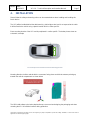
The VCU will be installed behind the dashboard (e.g. behind glove box) and is not exposed to the cabin.
It will be fixed to the vehicle using a plastic bracket which is carline specific.
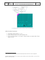
Exact mounting location of the VCU and its peripherals is carline specific. The below picture shows an
schematic / example.
VCU Example VCU and external antenna mounting location
Mounting direction shall be vertical with the connectors facing down and with the antenna pointing up
towards the vehicle compartment as shown below.
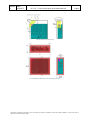
The OEM shall adhere to the below depicted keep-out zones when designing the packaging and when
mounting the VCU in individual carlines during production.
VCU
Ext.
Ant

Version:
1
Date:
9/29/2023
VCU 1.0 - Technical Description and Installers Manual
Page 8
© Robert Bosch GmbH 2022. All rights reserved, also regarding any disposal, exploitation, reproduction, editing, distribution, as well as in the event of
applications for industrial property rights.
VCU Antenna Keep-Out Zone
VCU Mandatory (Minimum) Thermal Keep-Out Zone

Version:
1
Date:
9/29/2023
VCU 1.0 - Technical Description and Installers Manual
Page 9
© Robert Bosch GmbH 2022. All rights reserved, also regarding any disposal, exploitation, reproduction, editing, distribution, as well as in the event of
applications for industrial property rights.
VCU Mandatory (Minimum) Keep-Out Zone for metal cross-vehicle beam
Additional Installation Requirements:
• Cable length to external Antenna: 1 – 1.5 m.
• Distance external Antenna to VCU (center of gravity): 55cm
• Minimal permissible distance
1
VCU internal / external Antenna and nearest interior Class-A
surface
2
: 47.1 mm
1
Measured from antenna dipol.
2
Class-A interior surface is any high-quality component that a passenger inside a vehicle can see, touch, or engage with

Version:
1
Date:
9/29/2023
VCU 1.0 - Technical Description and Installers Manual
Page 10
© Robert Bosch GmbH 2022. All rights reserved, also regarding any disposal, exploitation, reproduction, editing, distribution, as well as in the event of
applications for industrial property rights.
5. CERTIFICATION NOTICES AND REGULATORY
VERBIAGE
5.1. General Notices
Component Name: GM VCU 1.0
Type Designation: Cockpit Integration Platform (“CIP”)
Model Name: VCUNM1
Certificate Holder: Robert Bosch GmbH
Address: Robert-Bosch-Platz 1
70839 Gerlingen
Germany
This equipment shall be installed and operated according to the defined installation requirements
including the minimum distance between the VCU internal / external antenna and the nearest interior
Class-A surface.
External antenna to nearest interior Class-A surface min. distance of 47.11 mm
Internal antenna to nearest interior Class-A surface min. distance of 197 mm
Declaration of WiFi Transmission Power:
WLAN 2412 – 2462 MHz <20 dBm
WLAN 5150 – 5250 MHz & 5750 – 5850 MHZ <20 dBm
5.2. Additional Country Specific Requirements
5.2.1. USA
This device complies with Part 15 of the FCC Rules.
Operation is subject to the following two conditions:
(1) this device may not cause harmful interference, and
(2) this device must accept any interference received, including interference that may cause undesired
operation.
To comply with FCC Exposure requirements the OEM is instructed by the Grantee to assure a minimum
separation distance of 47mm between the housing where the integrated antenna is located and any
human body as documented in the filing.
Changes or modifications not expressly approved by the party responsible for compliance could void the
user’s authority to operate the equipment.
5.2.2. Canada
This device contains licence-exempt transmitter(s)/receiver(s) that comply with Innovation, Science and
Economic Development Canada’s licence-exempt RSS(s). Operation is subject to the
following two conditions:
(1) This device may not cause interference.

Version:
1
Date:
9/29/2023
VCU 1.0 - Technical Description and Installers Manual
Page 11
© Robert Bosch GmbH 2022. All rights reserved, also regarding any disposal, exploitation, reproduction, editing, distribution, as well as in the event of
applications for industrial property rights.
(2) This device must accept any interference, including interference that may cause undesired operation
of the device.
L’émetteur/récepteur exempt de licence contenu dans le présent appareil est conforme aux CNR d’Inno-
vation, Sciences et Développement économique Canada applicables aux appareils radio exempts de li-
cence. L’exploitation est autorisée aux deux conditions suivantes :
1. L’appareil ne doit pas produire de brouillage;
2. L’appareil doit accepter tout brouillage radioélectrique subi, même si le brouillage est susceptible d’en
compromettre le fonctionnement.
-
 1
1
-
 2
2
-
 3
3
-
 4
4
-
 5
5
-
 6
6
-
 7
7
-
 8
8
-
 9
9
-
 10
10
-
 11
11


Bosch VCUNM1 Manuel utilisateur
- Catégorie
- Antennes réseau
- Taper
- Manuel utilisateur
dans d''autres langues
- English: Bosch VCUNM1 User manual
Autres documents
-
Acson IM-VCUA-0304-ACSON Guide d'installation
-
Hilti DCH 300 Mode d'emploi
-
-
Casio FC-100V, FC-200V Le manuel du propriétaire
-
Hilti DD 110-D Mode d'emploi
-
-
-
-
Casio ClassPad II fx-CP400 Exemples
-
Novamatic FH68-VCU Manuel utilisateur