
Quick Start Guide
Arista 5000 Series Enterprise WAN Routers
5310 and 5510
Arista Networks
www.arista.com
DOC-06420-01

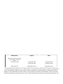
Support Sales
+1-408-547-5502
+1-866-476-0000 +1-408-547-5501
+1-866-497-0000
Headquarters
5453 Great America Parkway
Santa Clara, CA 95054
USA
+1-408-547-5500
© Copyright 2023 Arista Networks, Inc. All rights reserved. The information contained herein is subject to change without
notice. The trademarks, logos and service marks ("Marks") displayed in this documentation are the property of Arista
Networks in the United States and other countries. Use of the Marks are subject to Arista Network Terms of Use Policy,
available at www.arista.com/en/terms-of-use. Use of marks belonging to other parties is for informational purposes only.

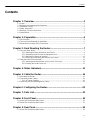
Contents
Contents
Chapter 1: Overview........................................................................................1
1.1 Scope.................................................................................................................................................1
1.2 Receiving and Inspecting the Equipment..........................................................................................1
1.3 Installation Process............................................................................................................................1
1.4 Safety Information..............................................................................................................................2
1.5 Obtaining Technical Assistance........................................................................................................ 2
1.6 Specifications.....................................................................................................................................2
Chapter 2: Preparation....................................................................................4
2.1 Site Selection.....................................................................................................................................4
2.2 Tools and Parts Required for Installation..........................................................................................5
2.3 Electrostatic Discharge (ESD) Precautions.......................................................................................5
Chapter 3: Rack Mounting the Router..........................................................7
3.1 Four-post Rack Mount.......................................................................................................................7
3.1.1 Attaching Mounting Brackets to the Chassis.......................................................................8
3.1.2 Assembling the Rails onto the Equipment Rack.................................................................9
3.1.3 Attaching the Router to the Rack......................................................................................11
3.1.4 Removing the Mounting Bracket from the Chassis...........................................................11
3.2 Two-post Rack Mount (Optional).................................................................................................... 12
3.2.1 Attaching Mounting Brackets to the Chassis (Two-post)...................................................12
3.2.2 Inserting the Router into Rack...........................................................................................13
Chapter 4: Status Indicators........................................................................15
Chapter 5: Cable the Router........................................................................16
5.1 Grounding the Router......................................................................................................................16
5.2 Connecting Power Cables...............................................................................................................18
5.2.1 AC Power Supplies............................................................................................................18
5.3 Connecting Serial and Management Cables...................................................................................19
Chapter 6: Configuring the Router..............................................................20
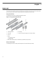
Chapter 7: Parts List.....................................................................................22
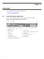
Chapter 8: Front Panel................................................................................. 24
8.1 Arista 5310 Enterprise WAN Router...............................................................................................24
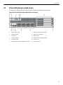
8.2 Arista 5510 Enterprise WAN Router...............................................................................................25
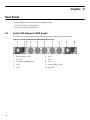
Chapter 9: Rear Panel...................................................................................26
9.1 Arista 5310 Enterprise WAN Router...............................................................................................26
iii

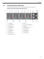
9.2 Arista 5510 Enterprise WAN Router...............................................................................................26
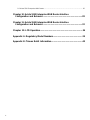
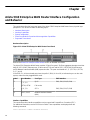
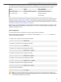
Chapter 10: Arista 5310 Enterprise WAN Router Interface
Configuration and Behavior.....................................................................28
Chapter 11: Arista 5510 Enterprise WAN Router Interface
Configuration and Behavior.....................................................................32
Chapter 12: LCD Operation..........................................................................36
Appendix A: Regulatory Model Numbers...................................................39
Appendix B: Taiwan RoHS Information......................................................40
iv

Chapter 1
Overview
This guide is intended for network professionals who need to install the Arista 5000 Series Enterprise
WAN Routers.
The following topics are covered in this section:
•Scope
•Receiving and Inspecting the Equipment
•Installation Process
•Safety Information
•Obtaining Technical Assistance
•Specifications
1.1 Scope
This section lists the routers that are described in this guide:
• Arista 5310 Enterprise WAN Router
• Arista 5510 Enterprise WAN Router
CAUTION: Only qualified or trained personnel should install, service, or replace this equipment.
Seul le personnel qualifié doit installer, service, ou remplacer cet équipement.
1.2 Receiving and Inspecting the Equipment
Upon receiving the router, inspect the packaging and record if there is any external damage. Retain the
packing material if you suspect that any part of the shipment is damaged; the carrier might need the packing
material to inspect.
If the packaging was not damaged during transit, unpack each box carefully. Ensure that you do not discard
any accessories that may be packed in the same box as the router.
Review the packing list that comes with the router to ensure you have received all the items listed. Refer to
the Parts List to verify that all components are included.
1.3 Installation Process
This section describes the steps required to install and use the router in a Data Center environment:
1. Select and prepare the installation site. (Site Selection)
2. Assemble the installation tools listed. (Tools and Parts Required for Installation)
3. Attach the mounting brackets and install the router in an equipment rack. (Rack Mounting the Router)
4. Connect the router to the power source, console cables, and management network. (Cable the Router)
5. Configure the router. (Configuring the Router)
1

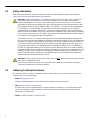
1.4 Safety Information
Refer to the Arista Networks document Safety Information and Translated Safety Warnings available at
https://www.arista.com/en/support/product-documentation.
Important: Class 1 laser product: This product has provisions to install Class 1 laser transceivers
which provide optical coupling to the communication network. Once a Class 1 laser product is
installed, the equipment is a Class 1 laser product (Appareil à Laser de Classe 1). The customer is
responsible for selecting and installing the Class 1 laser transceiver and for ensuring that the Class 1
AEL (allowable emission limit) per EN/IEC 60825, CSA E60825-1, and Code of Federal Regulations
21 CFR 1040 is not exceeded after the laser transceiver has been installed. Do not install laser
products whose class rating is greater than 1. Refer to all safety instructions that accompanied the
transceiver prior to installation. Only Class 1 laser devices certified for use in the country of installation
by the cognizant agencies are to be utilized in this product. Ultimate disposal of this product should be
in accordance with all applicable laws and regulations.
Produit laser de classe 1: Ce produit a des dispositions pour installer des émetteurs-récepteurs de
laser de classe 1 qui offre de couplage au réseau de communication optique. Une fois un produit laser
de classe 1 est installé, l'équipement est un produit laser de classe 1 (Appareil à laser de Classe 1).
Le client est responsable pour sélectionner et installer l'émetteur/récepteur de laser de classe 1 et
pour assurer que la classe 1 AEL (limite d'émission admissible) par EN/IEC 6-825, CSA E60825-1,
et Code des règlements fédéraux 21 CFR 1040 ne soit pas dépassée après avoir installé l'émetteur/
récepteur de laser. Ne pas installer des appareils à laser dont la cote de classe est supérieure à 1.Voir
toutes les consignes de sécurité qui ont accompagné l'émetteur-récepteur avant l'installation. Seuls
appareils laser de classe 1 certifiés pour une utilisation dans le pays d’installation par l’organisme
compétent doivent être utilisées dans ce produit.
Important: DO NOT open the case of the router. There are NO user serviceable parts inside. Entrust
any repair to a qualified technician.
N’ouvrez PAS le boîtier du routeur. Il n’y a AUCUNE pièce réparable par l’utilisateur à l’intérieur.
Confiez toute réparation à un technicien qualifié.
1.5 Obtaining Technical Assistance
Any customer, partner, reseller, or distributor holding a valid Arista Service Contract can obtain technical
support in any of the following ways:
•Email: [email protected]
Include a detailed description of the problem and the output of “show tech-support”.
•Web: https://www.arista.com/en/support
A support case may be created through the support portal on our website. You may also download the
most current software and documentation, as well as view FAQs, Knowledge Base articles, Security
Advisories, and Field Notices.
•Phone: +1 866-476-0000 or +1 408-547-5502
2

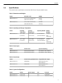
Overview
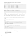
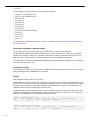
Table 1: Dimensions and Weights
Router Size (W x H x D) Weight
AWE-5310-2F-FLX 17.32 x 1.71 x 16.92 inches
(440 x 43.5 x 430 mm)
20.5 lbs
(9.3 kg)
AWE-5510-2F-FLX 17.32 x 3.46 x 20.47 inches
(440 x 88 x 520 mm)
29.98 lbs
(13.6 kg)
Table 2: Operating and Storage Temperature
Router Operating
Temperature Storage
Temperature Operating Altitude Relative
Humidity
AWE-5310-2F-FLX 32° to 104°F
(0° to 40°C)
-13° to 158°F
(-25° to 70°C)
0 to 10,000 feet
(0 to 3,000 meters)
5 to 95%
(non-
condensing)
AWE-5510-2F-FLX 32° to 104°F
(0° to 40°C)
-13° to 158°F
(-25° to 70°C)
0 to 10,000 feet
(0 to 3,000 meters)
5 to 95%
(non-
condensing)
Table 3: Power Input
Router Power Source Input Power Rating
AWE-5310-2F-FLX Power Input (AC Power) 100-240VAC, 8-4A, 50/60 Hz
AWE-5510-2F-FLX Power Input (AC Power) 100-240VAC, 10-5A, 50/60 Hz
Table 4: Power Draw
Router Power Draw (Typical/Maximum) Supported Power Supply
AWE-5310-2F-FLX 100W/500W AWE-5300-550-A-PS/
PWR-00619-01
AWE-5510-2F-FLX 200W/750W AWE-5500-800-A-PS/
PWR-00618-01
Table 5: System Configurations
Router Airflow Power Supply Fan Fan Type
AWE-5310-2F-FLX Front to rear 2 4+1 Fixed/built-in
AWE-5510-2F-FLX Front to rear 2 3+1 AWE-5500-A-FAN
3
1.6 Specifications
This section lists the specifications of the Arista 5000 Series Enterprise WAN Routers.

Chapter 2
Preparation
This section describes the initial setup and preparation for installing the Arista 5310 and 5510 Enterprise
WAN Routers.
The following topics are covered in this section:
•Site Selection
•Tools and Parts Required for Installation
•Electrostatic Discharge (ESD) Precautions
2.1 Site Selection
The following criteria should be considered when selecting a site to install the router in a Data
Center environment:
•Temperature and Ventilation: For proper ventilation, install the router where there is ample airflow to the
front and back of the router.
Important: To prevent the device from overheating, do not operate it in an area where the ambient
temperature exceeds 104°F (40°C).
Pour empêcher l’interrupteur de surchauffe, ne pas utiliser il dans une zone où la température
ambiante est supérieure à 104°F (40°C).
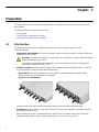
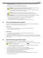
•Airflow Orientation: The fans and PSUs determine the airflow direction through the router. The color of
the visible handles or labels indicates the airflow direction.
•Red Handle: Red handle represents the air exit module. The following figure shows the airflow
direction through the router with an air exit module.
Figure 2-1: Air Exit Modules
Orient the router such that the airflow through the router is from the cooler to the hotter aisle.
•Rack Space: Install the router in a 19" rack or cabinet. The accessory kit provides mounting brackets for
two-post and four-post racks.
When mounting the router in a partially filled rack, load the rack from bottom to top, with the heaviest
equipment at the bottom. Load the router at the bottom if it is the only item in the rack.
4

Preparation
•Power Requirements: Power requirements vary by each router and power supply model. Refer to
Specifications for information regarding your specific system.
Refer to Cable the Router section for power cable requirements.
Important: The power input plug-socket combination must be accessible at all times as it also
provides the primary method of disconnecting power from the system.
La combinaison de la puissance-prise d’entrée doit être accessible en tout temps; Il fournit le
principal moyen de coupure d’alimentation du système.
Important: All power connections must be removed to de-energize the device.
Toutes les connexions d’alimentation doivent être enlevées pour hors tension l’appareil.
•Other Requirements: Select a site where liquids or objects cannot fall onto the equipment and foreign
objects are not drawn into the ventilation holes. Verify the following guidelines are met:
• Clearance areas to the front and rear panels allow for unrestricted cabling.
• All front and rear panel indicators can be easily read.
• Power cords can reach from the power outlet to the connector on the rear panel.
2.2 Tools and Parts Required for Installation
Each router comes with an accessory kit that contains parts that are required to install. In addition to the
accessory kit, the following tools are required to install the router:
Four-post Rack
• #1 and #3 Phillips head screwdrivers (this may differ based on supplied accessories)
• Screws or rack-mounting nuts and bolts
Two-post Rack
• #1 and #3 Phillips head screwdrivers (this may differ based on supplied accessories)
• Screws or rack-mounting nuts and bolts
The accessory kit should include screws for attaching the router into an equipment rack. When installing the
router to an equipment rack with unthreaded post holes, nuts and bolts are also required to secure the router
to the rack posts.
2.3 Electrostatic Discharge (ESD) Precautions
Observe these guidelines to avoid ESD damage when installing or servicing the router:
Important: DO NOT open the case of the router. There are NO user serviceable parts inside. Entrust
any repair to a qualified technician.
N’ouvrez PAS le boîtier du routeur. Il n’y a AUCUNE pièce réparable par l’utilisateur à l’intérieur.
Confiez toute réparation à un technicien qualifié.
• Assemble or disassemble the equipment only in a static-free work area.
• Use a conductive work surface (such as an anti-static mat) to dissipate static charge.
• Wear a conductive wrist strap to dissipate static charge accumulation.
• Minimize handling of assemblies and components.
• Keep replacement parts in their original static-free packaging.
• Remove all plastic, foam, vinyl, paper, and other static-generating materials from the work area.
5
• Use tools that do not create ESD.

Chapter 3
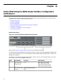
Rack Mounting the Router
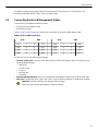
This section provides the instructions to rack mount the router.
The following table shows the list of supported rack mount brackets.
Table 6: Supported Rack Mount Brackets
Router Two-post Rack Mount Four-post Rack Mount
AWE-5310-2F-FLX KIT-2POST-1U-NT KIT-4POST-NT (default)
KIT-7101-RK
KIT-7101-LD-RK
AWE-5510-2F-FLX KIT-2POST KIT-4POST-NT (default)
KIT-7101-RK
KIT-7101-LD-RK
The following topics are covered in this section:
•Four-post Rack Mount
•Two-post Rack Mount (Optional)
Note: Four-post rack mount is recommended for all routers. Use the rack-mount parts included with
the router for mounting.
3.1 Four-post Rack Mount
This section provides instructions for mounting the router in a four-post rack.
The router is mounted onto a four-post rack by assembling two rails onto the rear posts, sliding the router
onto the rails, then securing the router to the front posts.
The installation kit provides the following four-post mounting parts:
• Two six-hole mounting brackets
• Two rail rods
• Two rail slides
The rail rods and rail slides assemble into two identical slide rails.
Each chassis side has attachment pins that align with bracket holes. Pin orientation is symmetric and
equidistant, supporting bracket placements where the flange is flush with the front panel, flush with the rear
panel, or not flush with either panel. Each bracket hole includes a key-opening for placing the bracket flush
with the chassis and then locking it into place.
Important: Attachment pins must engage at least five of the six bracket holes.
Goupilles de fixation doivent être lock au moins cinq des trous du six support.
7

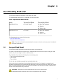
The following figure displays proper bracket mount configuration examples for four-post mounting.
Figure 3-1: Bracket Mount Configuration for Four-post Rack Mount (Example)
The following figure displays an improper bracket mount configuration example.
Figure 3-2: Improper Bracket Mount Configuration for Four-post Rack Mount (Example)
The following topics are covered in this section:
•Attaching Mounting Brackets to the Chassis
•Removing the Mounting Bracket from the Chassis
3.1.1 Attaching Mounting Brackets to the Chassis
This section describes the steps to attach mounting brackets to the chassis.
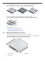
The following figure displays the front bracket alignment for mounting the router into a four-post rack.
Figure 3-3: Attaching the Mounting Brackets to the Router Chassis
1 Mounting bracket 3 Rail flanges
2 Rack plugs
8

Rack Mounting the Router
Figure 3-4: Aligning the Rack Plugs to the Bracket Clip
1 Bracket clip before it is locked in the
specified place. 2 Bracket clip after it is locked in the
specified place.
1. Align the mounting brackets with the attachment pins to obtain the desired mounting position.
2. Place the bracket flush to the chassis with the attachment pins protruding through the key openings.
3. Slide the bracket toward the front flange until the bracket clip locks with an audible click.
To remove the mounting bracket from the chassis, lift the front edge of the mounting bracket clip
with a flat-head screwdriver and slide the bracket away from the front flange (opposite from the
installation direction).
3.1.2 Assembling the Rails onto the Equipment Rack
Rail rods and rail slides assemble into two identical rails. Each rail connects a front post to a rear post. When
the rails are installed, the router slides on the rails into the rack. Each bracket includes a screw that attaches
the router to the rail.
Each end of an assembled rail contains two rack plugs. The rails are installed into a rack by inserting the
plugs into rack slots. When installing rails into rack posts with threaded or rounded holes, remove all plugs
located on both sides of the assembled rails, then install the rails with bolts that fit the rack.
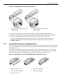
Figure 3-5: Attaching the Four-Post Mounting Brackets to the Router Chassis
1 Attach rail slide to router 4 Bracket clip (attached)
2 Slide rail rod onto rail slide 5 Bracket clip (aligned)
3 Attach bracket clip
9

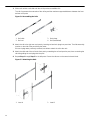
1. Slide a rail rod into a rail slide until the rail clip makes an audible click.
The rail clip prevents the extension of the rail beyond the maximum supported distance between the front
and rear rack posts.
Figure 3-6: Assembling the Rails
1 Rail slide 3 Rack plugs
2 Rail rod 4 Rail (assembled)
2. Attach the rail to the right rear rack post by inserting rod-end rack plugs into post slots. The slide assembly
must be on the side of the post facing the router.
If the rack plugs were previously removed, use bolts to attach the rail to the rack.
3. Attach the slide end of the rail to the front post by extending the rail end past the post, then contracting the
rail while guiding the rack plugs into the post.
4. Repeat Step 1 through Step 3 for the left posts. Ensure the rails are on the same horizontal level.
Figure 3-7: Attaching the Rails
1 Inset A 2 Inset B
10

Rack Mounting the Router
3.1.3 Attaching the Router to the Rack
Once the rails are installed, the router slides into the rack. Each bracket includes a thumb screw that attaches
the router to the rail.
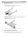
1. Lift the router into the rack and insert the mounting brackets into the slide rails.
Figure 3-8: Inserting the Router onto the Rails
2. Slide the router on the rails, toward the rear posts, until the mounting bracket flanges are flush with the rail
flanges attached to the rack posts.
3. Attach the bracket flanges to the rack post using the quick-release thumb screws supplied with
the brackets.
Figure 3-9: Attaching the Router to the Rack Posts
After completing the four-post rack mount, proceed to Cable the Router section.
3.1.4 Removing the Mounting Bracket from the Chassis
This section describes the steps to remove the mounting brackets from the router chassis.
1. Lift the front edge of the mounting bracket clip with a flat-head screwdriver.
2. Slide the bracket away from the front flange (opposite from the installation direction).
11

3.2 Two-post Rack Mount (Optional)
This section provides instructions for mounting the router in a two-post rack.
To mount the router onto a two-post rack, assemble the mounting brackets to the chassis, then attach the
brackets to the rack posts. Two-post accessory kits include the following two-post mounting parts.
Two Three-hole Mounting Brackets
Each chassis side has attachment pins that align with bracket holes. Pin orientation is symmetric and
equidistant, supporting bracket placements where the flange is flush with the front panel, flush with the rear
panel, or not flush with either panel. Each bracket hole includes a key opening for placing the bracket flush
with the chassis and then locking it into place.
Important: Attachment pins must engage all three upper bracket holes.
Goupilles de fixation doivent être bloquer tous les trois trous de la bride supérieure.
The following topics are covered in this section:
•Attaching Mounting Brackets to the Chassis (Two-post)
•Inserting the Router into Rack
3.2.1 Attaching Mounting Brackets to the Chassis (Two-post)
This section describes the steps to attach mounting brackets to the router chassis.
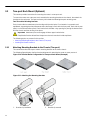
The following figure displays the front bracket alignment for attaching the router to a two-post rack.
Figure 3-10: Bracket Mount Configuration for Two-post Rack Mount (Example)
Figure 3-11: Attaching the Mounting Brackets
1 Bracket clip installation 2 Bracket clip removal
12

Rack Mounting the Router
The following figure displays improper bracket mounts for two-post rack mount.
Figure 3-12: Improper Bracket Mount Configuration for Two-post Rack Mount (Example)
1. Align the mounting brackets with the attachment pins to obtain the desired mounting position.
2. Place the bracket flush on the chassis with attachment pins protruding through key openings.
3. Slide the bracket toward the front flange until the bracket clip locks with an audible click.
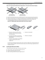
The following figure shows the correct bracket attachment for a front mount.
Figure 3-13: Attaching the Mounting Brackets to the Router Chassis
1 Align the mounting brackets with the
attachment pins to obtain the desired
mounting position.
4 Bracket clip (attached)
2 Place the bracket flush on the chassis
with attachment pins protruding through
key openings.
5 Bracket clip (aligned)
3 Slide the bracket toward the front flange
until the bracket clip locks with an
audible click.
To remove the mounting bracket from the chassis, lift the front edge of the mounting bracket clip
with a flat-head screwdriver and slide the bracket away from the front flange (opposite from the
installation direction).
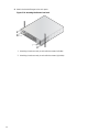
3.2.2 Inserting the Router into Rack
This section describes the steps to insert the router into rack.
1. Lift the chassis, with the brackets attached, into rack.
2. Position the flanges against rack posts.
3. Select mounting screws that fit your equipment rack.
13

4. Attach the bracket flanges to the rack posts.
Figure 3-14: Inserting the Router into Rack
1 Attaching chassis securely to rack with the screws (left side)
2 Attaching chassis securely to rack with the screws (right side)
14

Chapter 4
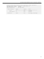
Status Indicators
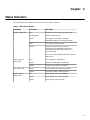
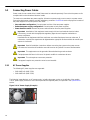
This section describes meaning of the front-panel LED status indicators.
Table 7: LED Status Indicators
LED Name LED State LED Status
Off No power or in the midst of a power cycle.
Blinking green System is powering up.
Green The system is operating in a normal
initialization sequence. Normal operations.
Blue The locator function is active.
System Status LED
Amber System is malfunctioning. System is
overheating or temperature sensors have
recorded passing the software-defined
critical threshold.
The router will automatically execute a reboot/
power cycle.
Off Not connected to CloudVision.
Green System is connected to CloudVision.
Cloud Connect
Status LED
Amber Problem connecting to CloudVision.
Green All fan modules are operating normally.Fan Status LED
Amber Single fan module is malfunctioning.
Off Power supply unit is not available.
Green Power supply unit is fully functional.
Power Supply
Status LED
Amber Power supply unit has a fault.
15

Chapter 5
Cable the Router
The following topics are covered in this section:
•Grounding the Router
•Connecting Power Cables
•Connecting Serial and Management Cables
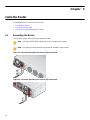
5.1 Grounding the Router
This section provides instructions for grounding the router.
Note: Grounding cable and grounding lugs are not included with the router.
16
Note: The cable size should meet local and national installation requirements.
Figure 5-1: Functional Grounding Pad Sockets 5310 Rear Panel
Figure 5-2: Functional Grounding Pad Sockets 5510 Rear Panel

Cable the Router
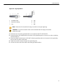
Figure 5-3: Lug Preparation
1 Insulated cable A 1/4″
2 Heat-shrink tubing B 1/2″
3 Lug C 5/8″
Note: Dimension B is the width of the lug (not visible on the right-angle lug).
CAUTION: The earth connection must not be removed unless all supply connections
are disconnected.
1. Ensure the rack is properly grounded and is in compliance with ETSI EN 300 253.
2. Ensure that there is a good electrical connection to the grounding point on the rack (no paint or isolating
surface treatment).
17
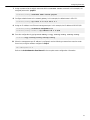
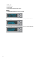
3. Attach the solder terminal lug to an 18 AWG minimum grounding cable, and connect it to the grounding
point on the rear panel of the router.
4. Tighten the screw to secure the lug to the grounding point.
5. Connect the other end of the cable to the nearby grounded surface.
La page est en cours de chargement...
La page est en cours de chargement...
La page est en cours de chargement...
La page est en cours de chargement...
La page est en cours de chargement...
La page est en cours de chargement...
La page est en cours de chargement...
La page est en cours de chargement...
La page est en cours de chargement...
La page est en cours de chargement...
La page est en cours de chargement...
La page est en cours de chargement...
La page est en cours de chargement...
La page est en cours de chargement...
La page est en cours de chargement...
La page est en cours de chargement...
La page est en cours de chargement...
La page est en cours de chargement...
La page est en cours de chargement...
La page est en cours de chargement...
La page est en cours de chargement...
La page est en cours de chargement...
La page est en cours de chargement...
-
 1
1
-
 2
2
-
 3
3
-
 4
4
-
 5
5
-
 6
6
-
 7
7
-
 8
8
-
 9
9
-
 10
10
-
 11
11
-
 12
12
-
 13
13
-
 14
14
-
 15
15
-
 16
16
-
 17
17
-
 18
18
-
 19
19
-
 20
20
-
 21
21
-
 22
22
-
 23
23
-
 24
24
-
 25
25
-
 26
26
-
 27
27
-
 28
28
-
 29
29
-
 30
30
-
 31
31
-
 32
32
-
 33
33
-
 34
34
-
 35
35
-
 36
36
-
 37
37
-
 38
38
-
 39
39
-
 40
40
-
 41
41
-
 42
42
-
 43
43


ARISTA AWE-5310-2 F-FLX Mode d'emploi
- Taper
- Mode d'emploi
- Ce manuel convient également à
dans d''autres langues
- English: ARISTA AWE-5310-2 F-FLX User guide
Autres documents
-
 Cabletron Systems GIGAswitch GSR-8 Getting Started Manual
-
Foundry Networks FES12GCF Guide d'installation
-
Oracle T5140 Guide d'installation
-
Delta Electronics AGC764V1 Guide d'installation
-
-
Dell PowerConnect B-TI24x Guide de démarrage rapide
-
Juniper ISG 2000 Manuel utilisateur
-
-
Cisco Systems CISCO7301 Manuel utilisateur
-
SonicWALL NSsp 12400 Guide de démarrage rapide
