
SERVICE MANUAL - MANUALE DI SERVIZIO
MANUEL DE SERVICE - BEDIENUNGSANLEITUNG
SDE 18
R 134a
Ice cubers
Fabbricatori
di ghiaccio a cubetti
Machines á glaçons
Kegeleisbereiter
REV. 01/2016

TABLE OF CONTENTS PAGE INDICE PAG TABLE DES MATIERES PAGE INHALT SEITE
GENERAL INFORMATION INFORMAZIONI GENERALI INFORMATIONS GENERALES ALLGEMEINES UND
AND INSTALLATION 1 ED INSTALLAZIONE 8 ET INSTALLATION 15 INSTALLATION 22
Introduction 1 Introduzione 8 Introduction 15 Einleitung 22
Unpacking and inspection 1 Disimballaggio ed ispezione 8 Déballage et examen 15 Auspacken und Inspektion 22
Location and levelling 1
Posizionamento e livellamento
10 Logement et mise de niveau 15
Maschinenplatz und lotgerechte
Aufstellung 28
Electrical connection 1 Collegamenti elettrici 9 Branchement électrique 15 Elektrische Anschlüße 23
Water supply and drain Alimentazione idraulica Branchement d’arrivée Wasserversorgung und
connection 2 e scarico 9 et d’évacuation eau 16 Abflußleitungen 23
Final check list 3 Controllo finale 10 Liste de contrôle final 16 Schlußkontrollen 24
Installation practice 3 Schema di installazione 12 Schema d’installation 17 Installation 24
OPERATING INSTRUCTION 4 ISTRUZIONI DI 11 MISE EN SERVICE 18 BETRIEBSANLEITUNG 25
FUNZIONAMENTO
Start up 4 Avviamento 11 Démarrage 18 Inbetriebnahme 25
Operational checks 4 Controlli durante il funzion. 11
Contrôle pendant le fonctionn.
18 Kontrolle bei Betrieb 25
OPERATING PRINCIPLES 5 PRINCIPIO DI 12 PRINCIPE DE 19 FUNKTIONSSYSTEME 26
FUNZIONAMENTO FONCTIONNEMENT
Freezing cycle 5 Ciclo di congelamento 12 Cycle de congélation 19 Gefrierprozess 26
Harvest cycle 6 Ciclo di scongelamento 12 Cycle de démoulage 19 Abtauprozess 26
CLEANING INSTRUCTIONS OF ISTRUZIONI PER LA PULIZIA
INSTRUCTION DE NETTOYAGE
WARTUNGS UND
WATER SYSTEM 7 DEL CIRCUITO IDRAULICO 14
DU CIRCUIT HYDRAULIQUE
22
REINIGUNGSANLEITUNGEN
28
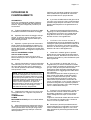
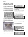
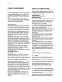
a)

b)

c)

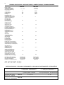
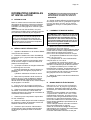
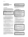
TECHNICAL SPECIFICATIONS - SPECIFICHE TECNICHE - DONNÉES TECHNIQUE - TECHNISCHE ANGABEN
SDN 20 SDN 20 W
Electric voltage
Alimentazione elettrica 230/50/1 230/50/1
Alimentation électrique -10 ÷ +10% -10 ÷ +10%
Normale Netzspannung
Condensation Air Water
Condensazione Aria Acqua
Condensation Air Eau
Kühlung Luft Wasser
Bin capacity (kg)
Capacità contenitore (kg)
Capacité bac glaçons (kg) 4 4
Speicher Kapazität (kg)
Net weight (kg)
Peso netto (kg)
Poids net (kg) 28 28
Netto Gewicht (kg)
Cubes per cycle
Cubetti per ciclo
Glaçons par cycle 1010
Würfel per Fase
Compressor power HP
Potenza compressore CV
Puissance compresseur CV 1/6 1/6
Kompressorleistung PS
Running amps
Amperaggio di marcia
Ampérage en marche 1,2 1,2
Ampere
Start amps
Amperaggio d’avv.
Ampérage de démarr. 6,56,5
Start Ampere
Power (Watts)
Potenza (Watt)
Puissance (Watts) 280 280
Leistung (Watt)
Power cons. in 24 hrs (Kwh)
Consumo elettr. in 24 ore (Kwh)
Cons. electr. en 24 hrs (Kwh) 5,3 4,4
Stromverbrauch in 24 Std. (kWh)
Wire size (mm )
Sezione cavi (mm )
Section fils (mm ) 3 x 1 3 x 1
Kabelanzahl (mm )
Water consumption (lt/hr)
Consumo acqua (lt/ora)
Consommation eau (lt/hr 1,9 15,8
Wasserverbrauch (lt/std)
Refrig. charge R 134 A (gr)
Carica refrig. R 134 A (gr)
Charge refrig. R 134 A (gr) 170 195
Kühlmittel - Füll. R 134 A (gr)
Refrigerant metering device Capillary tube Capillary tube
Disp. espansione refrigerante Tubo capillare Tubo capillare
Détente du Rèfrigérant Tube Capillaire Tube Capillaire
Kältemittel - Expansionssystem Kapillarrohr Kapillarrohr
Water - Acqua - Eau - Wasser: 15°C (60°F)
Envir. - Amb. - Amb. - Raum: 21°C (84°F)
2
2
2
2
d)
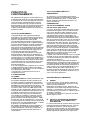
OPERATING PRESSURES - PRESSIONI DI FUNZIONAMENTO - PRESSIONES DE FONCTIONNEMENT - BETRIEBSDRÜCKE
Discharge pressure - Pressione di mandata Suction pressure - Pressione di aspirazione
Haute pression - Hochdruckbereich Basse pression - Niederdrück
Freezing cycle - Ciclo di congelamento End of freezing cycle - Fine ciclo di congelamento
Cycle de Congélation - Gefrierfase Fin du cycle de congélation - Ende der Gefrierfase
Air cooled - Raffr. ad aria 7.5 ÷ 10.5 bar 0,2 bar
Refroid. à air - Luftgekühlt
Water cooled - Raffr. ad acqua 6 ÷ 11 bar 0.1 bar
Refroid. à eau - Wassergekühlt
SDE 18 A
SDE 18 W
SDE 18 A
SDE 18 W

e)
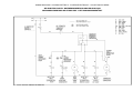
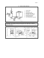
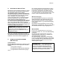
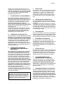
WIRING DIAGRAM - SCHEMA ELETTRICO - SCHÉMA ÉLECTRIQUE – SCHALTUNGSSCHEMA
AIR & WATER COOLED - RAFFREDDAMENTO AD ARIA ED AD ACQUA
REFROIDISSEMENT PAR AIR ET PAR EAU - LUFT UND WASSERGEKÜHLT

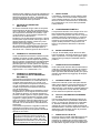
f)
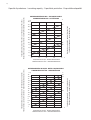
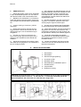
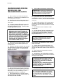
Capacità di produzione - Ice making capacity - Capacité de production - Eisproduktionskapazität
18,5
17,5
16,5
15,5
14,5
13,5
12,5
11,5
10,5
9,5
8,5
7,5
6,5
5,5
Kg.
RAFFREDDAMENTO AD ARIA - AIR COOLED MODELS
CONDENSATION PAR AIR - LUFTKÜHLUNG
TEMPERATURA ACQUA - WATER TEMPERATURE
TEMPÉRATURE DE L'EAU - WASSERTEMPERATUR
TEMPERATURA AMBIENTE - AMBIENT TEMPERATURE
TEMPÉRATURE AMBIANT - RAUMTEMPERATUR
PRODUZIONE GHIACCIO (KG PER 24 ORE) - ICE PRODUCED (KG. PER 24 HRS)
PRODUCTION DE GLACE (KG.PAR 24 HEURES) - EISWÜRFELPRODUKTION (KG.IN 24 STD.)
°C
10
21
32
38
32 27 15 10 °C
15
14,5
14
13,5
13
12,5
12
11,5
11
10,5
10
9,5
9
8,5
8
7,5
7
Kg.
RAFFREDDAMENTO AD ACQUA - WATER COOLED MODELS
CONDENSATION PAR EAU - WASSERKÜHLUNG
TEMPERATURA AMBIENTE - AMBIENT TEMPERATURE
TEMPÉRATURE AMBIANT - RAUMTEMPERATUR
PRODUZIONE GHIACCIO (KG PER 24 ORE) - ICE PRODUCED (KG. PER 24 HRS)
PRODUCTION DE GLACE (KG.PAR 24 HEURES) - EISWÜRFELPRODUKTION (KG.IN 24 STD.)
°C
10
21
32
38
21
32 27 15 10 °C21
TEMPERATURA ACQUA - WATER TEMPERATURE
TEMPÉRATURE DE L'EAU - WASSERTEMPERATUR

8. Remove the manufacturer’s registration
card from the inside of the User Manual and fill-
in all parts including: Model and Serial Number
taken from the data plate.
Forward the completed self-addressed
registration card to the factory.
C. LOCATION AND LEVELLING
WARNING. This Ice Cuber is designed for
indoor installation only. Extended periods
of operation at temperatures exceeding
the following limitations will constitute
misuse under the terms of the
Manufacturer’s Limited Warranty
resulting in LOSS of warranty coverage.
1. Position the unit in the selected permanent
location.
Criteria for selection of location include:
a) Minimum room temperature 10 °C and
maximum room temperature 43°C.
b) Water inlet temperatures: minimum 5°C
and maximum 35°C.
c) Well ventilated location for air cooled
models. Clean the air cooled condenser at
frequent intervals.
d) Service access: adequate space must
be left for all service connections through the
rear of the ice maker. A minimum clearance of 15
cm (6") must be left at the sides of the unit for
routing cooling air drawn into and exhausted out
of the compartment to maintain proper
condensing operation of air cooled models.
NOTE.
With the unit in “built-in” conditions,
the ice production is gradually reduced in
respect to the levels shown in the graph.
The daily ice-making capacity is directly
related to the condenser air inlet temperatu-
re, water temperature and age of the machine.
To keep your CUBER at peak performance
levels, periodic maintenance checks must
be carried out as indicated on Cleaning
Section of this manual.
2. Level the unit in both the left to right and
front to rear directions.
D. ELECTRICAL CONNECTIONS
See data plate for current requirements to
determine wire size to be used on electrical
connections. All icemakers require a solid earth
wire.
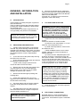
GENERAL INFORMA TION
AND INSTALLATION
A. INTRODUCTION
These Cubers are quality designed, engineered
and manufactured.
Their ice making systems are thoroughly tested
providing the utmost in flexibility to fit the needs
of a particular user.
These icemakers have been engineered to our
own rigid safety and performence standards.
NOTE.
To retain the safety and performance
built into this icemaker, it is important that
installation and maintenance be conducted
in the manner outlined in this manual.
B. UNPACKING AND INSPECTION
1. Visually inspect the exterior of the packing
and skid. Any severe damage noted should be
reported to the delivering carrier and a concealed
damage claim form filled in subjet to inspection of
the contents with the carrier’s representative
present.
2. a) Cut and remove the plastic strip securing
the carton box to the skid.
b) Cut open the top of the carton and remove
the polystyre protection sheet.
c) Pull out the polystyre posts from the
corners and then remove the carton.
3. Remove the front and the rear panels of the
unit and inspect for any concealed damage.
Notify carrier of your claim for the concealed
damage as steted in step 1 above.
4. Remove all internal support packing and
masking tape.
5. Check that refrigerant lines do not rub
against or touch other lines or surfaces, and that
the fan blade moves freely.
6. Use clean damp cloth to wipe the surfaces
inside the storage bin and the outside of the
cabinet.
7. See data plate on the rear side of the unit
and check that local main voltage corresponds
with the voltage specified on it.
CAUTION. Incorrect voltage supplied to
the icemaker will void your parts
replacement program.
Page 1

The ice machines are supplied from the factory
completely pre-wired and require only electrical
power connections to wire cord provided on the
back of the unit.
Make sure that the ice machine is connected to
its own circuit and individually fused (see data
plate for fuse size).
The maximum allowable voltage variation should
not exceed -10% and +10% of the data plate
rating. Low voltage can cause faulty functioning
and may be responsible for serious damage to
the overload switch and motor windings.
NOTE.
All external wiring should conform to
national, state and local standards and
regulations.
Check voltage on the line and the ice maker’s
data plate before connecting the unit.
E. WATER SUPPLY AND DRAIN
CONNECTIONS
General
When choosing the water supply for the ice cuber
consideration should be given to:
a) Length of run
b) Water clarity and purity
c) Adequate water supply pressure
Since water is the most important single ingredient
in producting ice you cannot emphasize too
much the three items listed above.
Low water pressure, below 1 bar may cause
malfunction of the ice maker unit.
Water containing excessive minerals will tend to
produce cloudy coloured ice cubes, plus scale
built-up on parts of the water system.
Water supply
Connect the 3/4" male fitting of the solenoid
water inlet valve, using the flexible tubing supplied,
to the cold water supply line with regular plumbing
fitting and a shut-off valve installed in an
accessible position between the water supply
line and the unit.
Water drain
The recommended drain tube is a plastic or
flexible tube with 18 mm (3/4") I.D. runs to an
open trapped and vented drain. When the drain
is a long run, allow 3 cm pitch per meter (1/4"
pitch per foot).
On water cooled versions, the water drain line
from the condenser is internally connected with
the drain fitting of the unit.
A vertical open vent, at the unit drain connection,
is also required for proper sump drainage.
NOTE.
The water supply and the water drain
must be installed to conform with the local
code. In some case a licensed plumber and/
or a plumbing permit is required.
Page 2

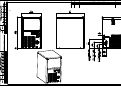
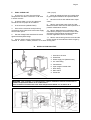
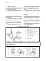
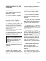
G. INSTALLATION PRACTICE
1. Hand shut-off valve
2. Water filter
3. Water supply line (flexible hose)
4. 3/4" male fitting
5. Vented drain
6. Open trapped vented drain
7. Drain fitting
8. Main switch
9. Power line
WARNING. This icemaker is not designed for outdoor installation and will not function in
ambient temperatures below 10°C or above 43°C.
This icemaker will malfunction with water temperatures below 5°C or above 35°C.
F. FINAL CHECK LIST
1. Is the unit in a room where ambient
temperatures are within a minimum of 10°C even
in winter months?
2. Is there at least a 15 cm (6") clearance
around the unit for proper air circulation?
3. Is the unit level? (IMPORTANT)
4. Have all the electrical and plumbing
connections been made, and is the water supply
shut-off valve open?
5. Has the voltage been tested and checked
against the data plate rating?
6. Has the water supply pressure been
checked to ensure a water pressure of at least
1 bar (14 psi).
7. Check all refrigerant lines and conduit lines
to guard against vibrations and possible failure.
8. Have the bin liner and cabinet been wiped
clean?
9. Has the owner/user been given the User
Manual and been instructed on the importance of
periodic maintenance checks?
10. Has the Manufacturer’s registration card
been filled in properly? Check for correct model
and serial number against the serial plate and
mail the registration card to the factory.
11. Has the owner been given the name and the
phone number of the authorized Service Agency
serving him?
Page 3

Page 4
OPERATING INSTRUCTIONS
START UP
After having correctly installed the ice maker and
completed the plumbing and electrical
connections, perform the following “Start-up”
procedure.
A. Remove the unit front panel and locate
the cleaning switch on the control box.
B. Set the cleaning switch in the cleaning
position. This will close the electrical circuit to the
water inlet valve and to the hot gas valve
C. Switch ON the power line disconnect
switch. Unit will start up in defrost cycle mode.
During this cycle the components energized are:
WATER INLET SOLENOID VALVE
HOT GAS SOLENOID VALVE
The Water pump and the Fan motor are also in
operation.
D. Let unit stay in defrost cycle for about
three/four minutes till water is coming out from
the drain hose, then move the cleaning switch to
the operation position.
NOTE.
During the defrost cycle, the water
inlet solenoid valve is energized. The water
flows through the valve to the back side of
the evaporator platen and then down to fill up
the icemaker sump tank for the next freezing
cycle.
OPERATIONAL CHECKS
E. The unit now starts its first freezing cycle
with the following components in operation:
COMPRESSOR
WATER PUMP
FAN MOTOR in air cooled version
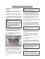
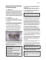
F. Check to see through the ice discharge
opening that the spray system is correctly seated
and that the water jets uniformely reach the
inverted molds; also make sure that the plastic
curtain is hanging freely and there is not excessive
water spilling through it.
G. The ice making process takes place
thereby, with the water sprayed on the inverted
molds that gets gradually refrigerated by the
heat exchanged with the refrigerant flowing into
the evaporator serpentine.
H. When the evaporator temperature reaches
a preset value the evaporator thermostat or cube
size control changes its contacts; the freezing
cycle ends and starts the defrost or harvest
cycle.
I. Check, during the first defrost/harvest
cycle, that the incoming water flows correctly
into the sump reservoir in order to re-fill it and the
surplus overflows through the overflow drain
tube.
J. Check the texture, the right weight and
dimension of ice cubes just released.
If not, wait for the second defrost/harvest cycle
before performing any adjustment.
K. If required, the length of the freezing cycle
can be modified by turning with very little
movements (6 degree or 1 minute each time) the
knob of the cube size control evaporator
thermostat located in front of the control box until
the desired size is achieved.
If the ice cubes are shallow and cloudy, it is
possible that the ice maker runs short of water
during the end of the freezing cycle or, the quality
of the supplied water requires the use of an
appropriate water filter or conditioner.
L. During the defrost or harvest cycle hold a
handful of ice cubes against the bulb of the
storage bin thermostat; the icemaker switch OFF
in about one-two minutes.
Take out the ice from the storage bin thermostat.
The ice maker should restart automatically in
three-four minutes.
NOTE.
The bin thermostat is factory set at
1
°
C OUT and 4
°
C IN.
M. Re-fit the unit front panel then instruct the
owner/user on the general operation of the ice
machine and about the cleaning and care it
requires.

Page 5
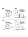
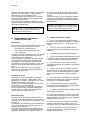
PRINCIPLE OF OPERATION
How it works
In the ice makers the water used to make the ice
is kept constantly in circulation by a water pump
which primes it to the spray system nozzles from
where it is diverted on the inverted molds of the
evaporator (Fig. A).
A small quantity of the sprayed water freezes into
ice; the rest of it cascades by gravity into the
sump assembly below for recirculation.
FREEZING CYCLE (Fig. B)
The hot gas refrigerant discharged out from the
compressor reaches the condenser where, being
cooled down, condenses into liquid. Flowing into
the liquid line it passes through the drier/filter,
then it goes all the way through the capillary tube
where it looses its pressure.
Next the refrigerant enters into the evaporator
serpentine (which has a larger diameter then the
capillary tube) and starts to boil off; this reaction
is emphasized by the heat transferred by the
sprayed water.
The refrigerant then increases in volume and
changes entirely into vapor.
The vapor refrigerant then passes through the
suction accumulator (used to prevent that any
small amount of liquid refrigerant may reach the
compressor) and through the suction line. In
both the accumulator and the suction line it
exchanges heat with the refrigerant flowing into
the capillary tube (warmer), before to be sucked
in the compressor and to be recirculated as hot
compressed refrigerant gas.
The freezing cycle is controlled by the evaporator
thermostat which has its bulb in contact with the
evaporator serpentine.
The electrical components in operation during
the freezing cycle are:
COMPRESSOR
WATER PUMP
FAN MOTOR (in air cooled version)
The refrigerant head pressure is gradually
reduced from a value of approx. 10,5 bars at the
beginning of the freezing cycle with the unit at
21°C ambient temperature, to a minimun value
of approx. 6 bars just at the end of the freezing
cycle few seconds before the starting of the
defrost cycle.
The declining of the pressure is relied to the
reduction of the evaporating pressure, caused
by the progressive growth of the ice thickness on
the inverted molds and to the flow of air drown
through the air cooled condenser by the fan
motor.
The above values are in relation as well to the
ambient temperature of the ice maker site and
they are subject to rise with the increase of this
temperature.
At the start of the freezing cycle the refrigerant
suction or lo-pressure lowers rapidly to 1.0 bar
then it declines gradually - in relation
with the growing of the ice thickness - to reach,
at the end of the cycle, approx. 0 ÷ 0.1 bar
with the cubes fully formed on the molds.
On the models water cooled version the hi-
pressure controls is used to intermittently
energize a water solenoid valve located on the
water supply line to the condenser.
DEFROST OR HARVEST CYCLE (Fig. D)
When the temperature of the evaporator
thermostat, in contact with the evaporator
serpentine, drops to a pre-set value it changes
its electrical contacts energizing the following
components:
COMPRESSOR
WATER INLET SOLENOID VALVE
HOT GAS SOLENOID VALVE
The incoming water, passing through the water
inlet valve and the flow control, runs over the
evaporator platen and then flows by gravity
through the interstices down into the sump/
reservoir (Fig. C).
The water filling the sump/reservoir forces part
of the surplus water from the previous freezing
cycle to go out to the waste through the overflow
pipe. This overflow limits the level of the sump
water which will be used to produce the next
batch of ice cubes.
Meanwhile the refrigerant, as hot gas discharged
from the compressor, flows through the hot gas
valve directly into the evaporator serpentine by-
passing the condenser.
The hot gas circulating into the serpentine of the
evaporator warms up the copper molds causing
the harvest of the ice cubes. The ice cubes,
released from the inveted molds, drop by gravity
onto a slanted cube chute, then through a
curtained opening they fall into the storage bin.
When the temperature of the evaporator
thermostat bulb reaches the value of +3 ÷4°C
their electrical contacts move back to the previous
position activating a new freezing cycle and
deenergizing both the hot gas and the water inlet
valves (closed).
NOTE. The length of the defrost/harvest
cycle (not adjustable) changes according
to the ambient temperature (shorter for hi
ambient temperature and longer for low
one).

COMPONENTS DESCRIPTION
A. WATER PUMP
The water pump operates continually throughout
the freezing cycle.
The pump primes the water from the sump to the
spray system and through the spray nozzles
sprays it into the inverted cup molds to be frozen
into crystal clear ice cubes.
It is recommended that the pump motor bearings
be checked at least every six months.
B. WATER INLET SOLENOID VALVE -
3/4 MALE FITTING
The water inlet solenoid valve is energized only
during the defrost cycle.
When energized it allows a metered amount of
incoming water to flow over the evaporator cavity
to assist the hot gas in defrosting the ice cubes.
The water running over the evaporator cavity
drops by gravity, through the dribbler interstices
of the platen, into the sump reservoir.
C. HOT GAS SOLENOID VALVE
The hot gas solenoid valve consists basically in
two parts: the valve body and the valve coil.
Located on the hot gas line, this valve is energized
by the contacts 3-2 of the evaporator thermostat
during the defrost cycle.
During the defrost cycle the hot gas valve coil is
activated so to attract the hot gas valve piston in
order to give way to the hot gas discharged from
compressor to flow directly into the evaporator
serpentine to defrost the formed ice cubes.
D. BIN THERMOSTAT
The bin thermostat control body is located in the
front of control box behind the front louvered panel.
The thermostat sensing tube is located into a
bulb holder on the side wall of the ice storage bin
where it automatically shuts the icemaker OFF
when in contact with the ice and re-starts the
icemaker when the ice is removed. Factory
settings are 1°C OUT and 4°C IN.
E. CUBE SIZE CONTROL (EVAPORATOR
THERMOSTAT)
The cube size control (evaporator thermostat)
body is located in the front of control box behind
the front louvered panel; it’s basically a reverse
acting temperature control which closes the
contacts 3-2 when its temperature decreases
and closes the opposite contacts 3-4 when the
temperature rises.
The thermostat sensing bulb is located into a
plastic tube (bulb holder) secured by two clips
directly to the evaporator serpentine.
This control determines the length of the freezing
cycle and correspondingly the size of the cubes.
A lower setting will produce a larger cube
(oversize) while a higher setting a smaller cuber
(shallow size).
When closed on contacts 3-2 it activates the
defrost or harvest cycle components.
The cube size control is set up in the factory
(knob in the black dot position) and doesn't
require any adjustment when the ambient
temperature remains between 10 and 35 °C.
NOTE. The thermostat is very sensitive!
By a little movement of the knob correspond
a big size change of the ice cubes. If
necessary only, it's recommended to make
max 1/20 of turn regulation each time.
F. FAN MOTOR
The fan motor is electrically connected in parallel
to the water pump and it operates continuously
only during the freezing cycle keeping the proper
head pressure by circulating air through the
condenser fins.
G. COMPRESSOR
The hermetic compressor is the heart of the
refrigerant system and it is used to circulate and
retrieve the refrigerant throughout the entire
system. It compresses the low pressure
refrigerant vapor causing its temperature to rise
and become high pressure hot vapor (hot gas)
which is then released through the discharge valve.
H. WATER SPRAY SYSTEM
Through its nozzles it sprays the water on each
individual inverted mold to be frozen into ice.
I
SAFETY HI TEMPERATURE THERMOSTAT
Located on the bottom part of the control box it is
a manual reset switch that trips OFF the operation
of the machine when its bulb (located on the
liquid line just before the drier) reaches the
temperature of 80°C.
J. CLEANING SWITCH
Located on the bottom left side of the control box
is used to energize the water inlet and the hot gas
valves so to charge the water into the sump tank
of the machine.
K. HI PRESSURE CONTROL
Used on water cooled ice makers it functions to
maintain the head pressure within the preset
values of 7,5 ÷10,5 bars, by intermittently activating
the water inlet valve to the condenser.
L. WATER INLET SOLENOID VALVE -
3/4 MALE FITTING
A second water inlet solenoid valve, operating
through an automatic hi-pressure control, is used
on water cooled versions to supply water to the
condenser.
When activated it supplies a metered amount of
water to the condenser in order to limit its tempe-
rature and the refrigerant operating high pr essure.
Page 6

Page 7
MAINTENANCE AND CLEANING INSTRUCTIONS
CLEANING INSTRUCTIONS OF WATER
SYSTEM
1. Remove the front and top panels to gain
access either to the control box and to the
evaporator.
2. Make sure that all ice cubes have been
released from their molds, then switch off the
unit.
3. Prepare the cleaning solution by diluting in
a plastic container one or two liters of warm water
(45°-50°C) with a 0,1-0,2 liters of Ice Machine
Cleaner.
WARNING. The Ice Machine Cleaner
contains Phosphoric and Hydroxyacetic
acids.
These compounds are corrosive and may
cause burns if swallowed, DO NOT indu-
ce vomiting. Give large amounts of water
or milk. Call Physician immediately.
In case of external contact flush with
water. KEEP OUT OF THE REACH OF
CHILDREN.
4. Scoop out all the ice cubes stored into the
bin in order to prevent them from being
contaminated with the cleaning solution then
flush out the water from the sump reservoir by
removing the overflow stand-pipe.
5. Remove the plastic cup located on the
bottom of sump/freezing chamber to drain out all
water and scale deposits.
6. Remove the evaporator cover then slowly
pour onto the evaporator platen the cleaning
solution. With the help of a brush dissolve the
most resistant and remote scale deposits in the
platen.
7. Turn the CLEANING switch on "II-CLEAN",
close the water tap and switch on the machine.
8. Allow the ice maker to operate for about 20
minutes.
NOTE.
The amount Cleaner and the time
needed for the cleaning of water system
depends of the water conditions.
9. Switch OFF then flush out the cleaning
solution from the sump reservoir then pour onto
the evaporator cavity two or three liters of clean
potable water to rinse the molds and the platen.
10. Switch ON the machine. The water pump is
again in operation to circulate the water in order
to rinse the entire water system.
11. Do the operation as per steps 8 and 9 twice
so to be sure no more traces of descaling solution
remains into the sump.
12. Pour on the upper side of the evaporator
platen fresh water with a capfull of disinfectant
solution then turn again the machine in normal
operating mode so to sanitize all the water system
for approx. 10 minutes.
NOTE.
Do not mix descaling with disinfectant
solution to avoid the generation of a very
aggressive acid.
13. Flush out the disinfectant solution from the
sump reservoir, open the water tap then switch
on the machine.
14. When water starts overflowing through
the drain line, set the switch to "operation"
position "I-ON". The unit is now ready to resume
normal operation.
15. Place again the evaporator cover and the
unit service panels.
16. At completion of the freezing and harvest
cycle make sure of proper texture and clearness
of the ice cubes and that, they do not have any
acid taste.
ATTENTION. In case the ice cubes are
cloudy-white and have an acid taste, melt
them immediately by pouring on them
some warm water. This to prevent that
somebody could use them.
17. Wipe clean and rinse the inner surfaces of
the storage bin.
REMEMBER.
To prevent the accumulation
of undesirable bacteria it is necessary to
sanitize the interior of the storage bin with an
anti-algae disinfectant solution every week.

Pagina 8
INFORMAZIONI GENERALI
ED INSTALLAZIONE
A. INTRODUZIONE
I fabbricatori di ghiaccio in cubetti sono stati
progettati e costruiti con un elevato standard
qualitativo.
Essi vengono collaudati interamente per diverse
ore e sono in grado di assicurare il massimo
rendimento relativamente ad ogni particolare
uso e situazione.
NOTA.
Per non compromettere o ridurre le
caratteristiche di qualità e sicurezza di que-
sto fabbricatore di ghiaccio si raccomanda,
nell’effettuare l’installazione e le operazioni
periodiche di manutenzione, di attenersi scru-
polosamente a quanto prescritto in questo
manuale.
B. DISIMBALLAGGIO ED ISPEZIONE
1. Ispezionare visivamente l’imballo esterno
in cartone e il basamento in legno usati per la
spedizione. Qualsiasi danno evidente sull’imbal-
lo esterno deve essere riferito allo spedizioniere;
in questo caso, procedere ad ispezionare l’appa-
recchio con il rappresentante dello spedizioniere
presente.
2. a) Tagliare e rimuovere i nastri in plastica
che mantengono sigillato l’imballo di cartone.
b) Aprire la parte superiore dell’imballo e
togliere i fogli e gli angolari protettivi di polistirolo.
c) Sollevare l’intero cartone sfilandolo dal-
l’apparecchio.
3. Togliere il pannello frontale ed il pannello
posteriore dell’apparecchio ed ispezionare lo
stesso onde accertare se abbia subito danni.
Notificare allo spedizioniere eventuali danni su-
biti come riportato al punto 1.
4. Togliere tutti i supporti interni usati per la
spedizione e i nastri adesivi di protezione.
5. Controllare che le tubazioni del circuito
refrigerante non tocchino altre tubazioni o super-
fici, e che il ventilatore giri liberamente.
6. Usando un panno pulito e umido, pulire le
pareti interne del contenitore del ghiaccio e le
superfici esterne dell’apparecchio.
7. Osservare i dati riportati sulla targhetta fis-
sata alla parte posteriore del telaio vicino ai
raccordi idraulici ed elettrici, e verificare che il
voltaggio della rete elettrica disponibile corri-
sponda a quello riportato sulla targhetta del-
l’apparecchio.
ATTENZIONE. Un errato voltaggio del-
l’alimentazione elettrica annullerà auto-
maticamente il vostro diritto alla garan-
zia.
8. Compilare la cartolina di garanzia posta
all’interno del Manuale d’Uso, segnando sia il
modello che il numero di serie dell’apparecchio
rilevandolo dalla targhetta fissata al telaio.
Spedire la cartolina debitamente compilata al
costruttore.
C. POSIZIONAMENTO E LIVELLAMENTO
ATTENZIONE. Questo fabbricatore di
ghiaccio è stato progettato per essere
installato all’interno di locali in cui la
temperatura ambiente non scenda mai al
di sotto di 10°C ne superi i 43°C.
Periodi prolungati di funzionamento a
temperature al di fuori dei seguenti limiti
costituiscono cattivo uso secondo i ter-
mini di garanzia e fanno decadere auto-
maticamente il vostro diritto alla garan-
zia.
1. Posizionare l’apparecchio nel luogo di in-
stallazione definitivo.
I criteri per la sua scelta sono:
a) Minima temperatura ambiente 10 °C e
massima temperatura ambiente 43°C.
b) Temperature dell’acqua di alimentazio-
ne: minima 5°C massima 35°C.
c) Luogo ben aerato per assicurare un
efficace ventilazione all’apparecchio e quindi un
corretto funzionamento del condensatore.
d) Spazio adeguato per i collegamenti di
servizio previsti nella parte posteriore dell’appa-
recchio. Lasciare almeno 15 cm di spazio attor-
no all’unità così da permettere una corretta ed
efficace circolazione d’aria soprattutto nei mo-
delli raffreddati ad aria.
NOTA.
Con l’apparecchio incassato la pro-
duzione di ghiaccio diminuisce rispetto a
quanto indica il diagramma.
La capacità di produzione giornaliera varia
con il variare della temperatura ambiente,
dell’acqua di alimentazione e dello spazio
intorno all’apparecchio.
Per mantenere la produzione del vostro
fabbricatore di ghiaccio a cubetti al massi-
mo della sua condizione è necessario ese-
guire la manutenzione periodica come pre-
scritto nel relativo capitolo di questo manua-
le.

Pagina 9
2. Livellare l’apparecchio in entrambe le dire-
zioni, dall’anteriore alla posteriore e da sinistra a
destra mediante i piedini.
NOTA.
Questo fabbricatore di ghiaccio in-
corpora dei componenti delicati e di massi-
ma precisione pertanto bisogna evitargli urti
e scossoni violenti.
D. COLLEGAMENTI ELETTRICI
Osservare la targhetta dell’apparecchio così da
determinare, in funzione dell’amperaggio indica-
to, tipo e sezione del cavo elettrico da usarsi.
Tutti gli apparecchi sono muniti di un cavo di
alimentazione elettrica per cui si richiede un
collegamento dello stesso ad una linea elettrica
provvista di cavo di messa a terra e che faccia
capo ad un proprio interruttore magneto-termico
munito di fusibili adeguati, come indicato nella
targhetta di ogni singolo apparecchio.
La variazione massima di voltaggio consentita
non deve eccedere il 10% del valore di targa o
essere inferiore al 10% dello stesso. Un basso
voltaggio può causare un funzionamento ano-
malo e può essere la causa di seri danni alle
protezioni ed agli avvolgimenti elettrici.
NOTA.
Tutti i collegamenti esterni devono
essere fatti a regola d’arte in conformità con
quanto stabilito dalle norme locali da parte di
personale qualificato.
Prima di collegare il fabbricatore di ghiaccio alla
linea elettrica accertarsi ancora una volta che il
voltaggio dell’apparecchio, specificato sulla
targhetta, corrisponda al voltaggio misurato.
E.
ALIMENTAZIONE IDRAULICA E SCARICO
Premessa
Nella scelta dell’alimentazione idraulica al
fabbricatore di ghiaccio a cubetti si deve tenere
presente:
a) Lunghezza della tubazione
b) Limpidezza e purezza dell’acqua
c) Adeguata pressione dell’acqua di alimen-
tazione
Una bassa pressione dell’acqua di alimentazio-
ne, inferiore ad 1 bar, può causare dei disturbi di
funzionamento dell’apparecchio. L’uso di acque
contenenti una quantità eccessiva di minerali
darà luogo ad una produzione di cubetti di ghiac-
cio opachi e ad una notevole incrostazione delle
parti interne del circuito idraulico.
Alimentazione idraulica
Collegare il raccordo da 3/4 di pollice maschio
della valvola solenoide di ingresso acqua alla
linea di alimentazione idrica utilizzando il tubo in
plastica rinforzato del tipo alimentare atossico
fornito.
La linea di alimentazione idraulica deve essere
munita di un rubinetto di intercettazione posto in
un luogo accessibile nei pressi dell’apparecchio.
Scarico acqua
Si consiglia di usare, come tubo di scarico, un
tubo in plastica rigida avente diametro interno di
18 mm.
Lo scarico dal condensatore, nei modelli raffred-
dati ad acqua, è raccordato internamente allo
scarico dell'apparecchio.
Lo scarico dell’acqua in eccesso avviene per
gravità; per avere un regolare deflusso è indi-
spensabile che lo scarico disponga di una presa
d’aria e vada in un sifone aperto.
NOTA.
Tutti i collegamenti idraulici devono
essere eseguiti a regola d’arte in conformità
con le norme locali. In alcuni casi è richiesto
l’intervento di un idraulico patentato.

Pagina 10
F. CONTROLLO FINALE
1. L’apparecchio è stato installato in un locale
dove la temperatura ambiente è di almeno 10°C
anche durante i mesi invernali?
2. Ci sono almeno 15 cm di spazio dietro ed ai
lati dell’apparecchio onde avere una efficace
ventilazione del condensatore?
3. L’apparecchio è ben livellato? (IMPORTAN-
TE)
4. L’apparecchio è stato collegato alla linea di
alimentazione elettrica? É stato eseguito il colle-
gamento alle tubazioni dell’acqua di alimentazio-
ne e di scarico?
5. É stato controllato il voltaggio della linea di
alimentazione elettrica? Corrisponde al voltag-
gio specificato sulla targhetta dell’apparecchio?
6. É stata controllata la pressione dell’acqua
di alimentazione in modo da assicurare all’appa-
recchio una pressione di ingresso di almeno 1
bar?
7. Controllare tutte le tubazioni del circuito
refrigerante e del circuito idraulico verificando se
esistono vibrazioni o sfregamenti. Controllare
inoltre che le fascette stringitubo siano ben ser-
rate e che i cavetti elettrici siano fermamente
collegati.
8. Sono stati controllati i bulloni di ancoraggio
del compressore? Permettono a questi di oscilla-
re sui propri supporti?
9. Le pareti interne del contenitore del ghiac-
cio e le pareti esterne dell’apparecchio sono
state pulite?
10. É stato consegnato il libretto di istruzione e
sono state date al proprietario le istruzioni neces-
sarie per il funzionamento e la manutenzione
periodica dell’apparecchio?
11. La cartolina di garanzia è stata compilata?
Controllare il numero di serie ed il modello sulla
targhetta dell’apparecchio, quindi spedirla al
costruttore.
12. É stato dato al proprietario il nome ed il
numero telefonico del servizio di assistenza tec-
nica autorizzato della zona?
G. SCHEMA DI INSTALLAZIONE
1. Rubinetto di intercettazione
2. Filtro acqua
3. Linea di alimentazione idraulica
4. Raccordo da 3/4 di pollice
5. Scarico ventilato
6. Scarico acqua con sifone ventilato
7. Raccordo di scarico
8. Interruttore principale
9. Linea elettrica
ATTENZIONE. Questo fabbricatore di ghiaccio non è stato progettato per essere installato
all’aperto o per funzionare a delle temperature ambienti inferiori a 10°C o superiori a 43°C.
Lo stesso vale per la temperatura dell’acqua di alimentazione che non deve essere inferiore
a 5°C o superiore a 35°C.

Pagina 11
Verificare che la tendina di plastica sia posizio-
nata correttamente impedendo la fuoriuscita
dell’acqua attraverso le proprie lamelle.
G. Il processo di fabbricazione del ghiaccio ha
così inizio con l’acqua che viene continuamente
spruzzata sugli stampini rovesciati e con la tem-
peratura dell’evaporatore che gradualmente si
abbassa.
H. Quando la temperatura dell'evaporatore
raggiunge un valore predeterminato il termosta-
to evaporatore commuta i suoi contatti dando
luogo alla fine del ciclo di congelamento ed
all'inizio del ciclo di scongelamento.
I. Verificare che durante la fase di
scongelamento l’acqua di alimentazione vada a
reintegrare quella precedentemente usata per la
produzione dei cubetti e che quella eccedente
trabocchi nel tubo di troppo pieno e fluisca nella
tubazione di scarico dell’apparecchio.
J. Osservare i cubetti di ghiaccio prodotti.
Questi devono essere della giusta dimensione.
Nel caso contrario, attendere il secondo ciclo di
produzione del ghiaccio, prima di effettuare qual-
siasi regolazione.
K. Se necessario la durata del ciclo di
congelamento può essere modificata ruotando
con piccolissimi spostamenti (spostare di 1/20 di
giro per volta) la manopola del termostato
evaporatore posta nella parte frontale della sca-
tola elettrica fino al raggiungimento della dimen-
sione ottimale.
Controllare l'aspetto dei cubetti di ghiaccio pro-
dotti: cubetti aventi delle corrette dimensioni
esterne ma particolarmente opachi, indicano
che il fabbricatore di ghiaccio ha avuto una
mancanza d'acqua durante la fase finale del
ciclo di congelamento o che, l'acqua usata per la
produzione del ghiaccio è di pessima qualità e
quindi si rende necessario l'uso di filtri adeguati
o di un condizionatore d'acqua.
L. Durante il ciclo di sbrinamento, coprire con
una manciata di cubetti il bulbo sensibile del
termostato contenitore e verificare lo spegni-
mento dell'apparecchio dopo circa due o tre
minuti.
Togliere la manciata di cubetti dal bulbo sensibi-
le e controllare che l'apparecchio si rimetta in
moto in circa tre o quattro minuti.
M. Rimontare i pannelli precedentemente ri-
mossi quindi istruire il proprietario sul funziona-
mento del fabbricatore di ghiaccio così come
sulle operazioni di pulizia ed igienizzazione del
medesimo.
ISTRUZIONI DI
FUNZIONAMENTO
AVVIAMENTO
Dopo aver correttamente installato l'apparec-
chio ed averlo collegato alla rete elettrica ed
idraulica, seguire la seguente procedura per
l'avviamento.
A. Togliere dal fabbricatore di ghiaccio il pan
nel-
lo frontale e localizzare l'interruttore di lavaggio.
B. Spostare l'interruttore di lavaggio sulla po-
sizione "II CLEAN". Questo chiude il circuito
elettrico della valvola di ingresso dell'acqua e
della valvola gas caldo.
C. Spostare, a questo punto sia l'interruttore
posto sulla linea di alimentazione elettrica che
l'interruttore generale dell'apparecchio sulla po-
sizione ON (acceso). L'apparecchio partirà nella
fase di sbrinamento con i seguenti componenti in
funzione:
VALVOLA INGRESSO ACQUA
VALVOLA GAS CALDO
Sono in funzione anche la Pompa ed il
Motoventilatore (nel caso di apparecchi raffred-
dati ad aria).
D. Lasciare funzionare la macchina nella fase
di sbrinamento per circa tre - quattro minuti fino
ad avere dell'acqua allo scarico dell'apparec-
chio. Quindi spostare l'interruttore di lavaggio
sulla posizione "I ON".
NOTA.
Durante la fase di sbrinamento l'ac-
qua entra nell'apparecchio, attraverso la val-
vola solenoide di ingresso dell'acqua, eccita-
ta durante questa parte del ciclo, e attraverso
l'apposita tubazione è indirizzata sulla parte
superiore dell'evaporatore. Dopo aver co-
perto l'intera superficie di plastica
dell'evaporatore, l'acqua viene scaricata, at-
traverso le fessure di drenaggio, nella
vaschetta di raccolta, riempiendola.
E. L'apparecchio inizia così il suo primo ciclo
di congelamento con i seguenti componenti in
funzione:
COMPRESSORE
POMPA
MOTOVENTILATORE (solo nei modelli raffred-
dati ad aria)
F. Osservare attraverso l’apertura di scarico
dei cubetti che la barra spruzzante sia corretta-
mente posizionata e che l’acqua venga unifor-
memente spruzzata sugli stampini rovesciati
dell’evaporatore.

Pagina 12
PRINCIPIO DI
FUNZIONAMENTO
Nei fabbricatori di ghiaccio l’acqua usata per la
produzione del ghiaccio è tenuta costantemente
in movimento da una pompa elettrica che attra-
verso un sistema spruzzante dirige l’acqua a
pressione moderata sugli stampini rovesciati
dell’evaporatore. Qui una parte dell’acqua spruz-
zata ghiaccia all’istante; il rimanente di essa
ricade nel sottostante serbatoio di recupero per
essere ricircolata.
CICLO DI CONGELAMENTO
Il refrigerante allo stato gassoso ed ad alta
temperatura viene pompato dal compressore e,
passando poi attraverso il condensatore, si tra-
sforma in refrigerante allo stato liquido.
La linea del liquido permette al refrigerante di
fluire dal condensatore al tubo capillare attraver-
so il filtro deumidificatore. Durante il passaggio
attraverso il tubo capillare il refrigerante allo
stato liquido perde gradualmente parte della sua
pressione e conseguentemente parte della sua
temperatura. Successivamente raggiunge ed
entra nella serpentina dell’evaporatore.
L’acqua spruzzata sugli stampini rovesciati
dell’evaporatore cede calore al refrigerante cir-
colante all’interno della serpentina, causandone
l’evaporazione, ed il conseguente cambiamento
del suo stato fisico, cioè da liquido diviene vapo-
re. Il refrigerante allo stato vaporoso dopo esse-
re passato attraverso l’accumulatore viene aspi-
rato nuovamente nel compressore tramite la
linea di aspirazione.
Il ciclo di congelamento è regolato da un control-
lo della temperatura (termostato evaporatore)
che determina la durata del ciclo e di conseguen-
za la dimensione dei cubetti.
I componenti in funzione durante il ciclo di
congelamento sono:
IL COMPRESSORE
LA POMPA
IL VENTILATORE (nei modelli raffreddati ad aria)
Nei modelli raffreddati ad aria la pressione di
mandata del sistema refrigerante (alta pressio-
ne) cala progressivamente da un valore di circa
10,5 bar (con temperatura ambiente di 21°C), che
si riscontra all’inizio del ciclo di congelamento,
fino ad un valore minimo di 7 bar proprio alla
fine del ciclo di congelamento. Questi valori sono
influenzati della temperatura dell’ambiente in cui
è installato l’apparecchio e aumentano propor-
zionalmente con l’aumentare di quest’ultima.
Con apparecchi installati in condizioni normali
(21°C ambiente) la pressione di aspirazione o
bassa pressione scende rapidamente a 1 bar
all’inizio del ciclo di congelamento, cioè quando
il cubetto di ghiaccio inizia a formarsi, declinando
lentamente a circa a 0÷0.1 bar allorché il cubetto
di ghiaccio è completamente formato.
Nei modelli raffreddati ad acqua è utilizzato un
pressostato per alimentare elettricamente, in
modo intermittente, una valvola a solenoide si-
tuata sulla linea idraulica di alimentazione al
condensatore.
CICLO DI SCONGELAMENTO O
SBRINAMENTO
Al momento in cui il termostato evaporatore
sente la temperatura corrispondente ai cubetti di
ghiaccio di dimensione piena, i contatti dello
stesso cambiano posizione alimentando i se-
guenti componenti:
COMPRESSORE
VALVOLA DI INGRESSO ACQUA
VALVOLA DEL GAS CALDO
L’acqua in immissione passa attraverso la valvo-
la solenoide di ingresso ed il controllo di flusso
che è posto all’interno della medesima, arriva
sulla parte superiore dell’evaporatore da dove
cola, attraverso le fessure di drenaggio, nel
sottostante serbatoio di pescaggio della pompa.
Il livello massimo dell’acqua nel serbatoio è limi-
tato da un tubo di troppo pieno che ha la funzione
di indirizzare verso lo scarico l’acqua in eccesso.
Il refrigerante allo stato gassoso, pompato dal
compressore, viene ora dirottato dalla valvola del
gas caldo aperta direttamente alla serpentina
dell’evaporatore, seguendo il percorso più diret-
to cioè, non passando attraverso il condensatore.
Il gas caldo circolante all’interno della serpentina
dell’evaporatore, fa aumentare la temperatura
degli stampini causando quindi lo stacco dai
medesimi dei cubetti di ghiaccio.
I cubetti che si staccano cadono sopra una griglia
inclinata da dove scivolano attraverso l’apertura
con tendina a lamelle, per cadere all’interno del
contenitore del ghiaccio.
Grazie al fluire del gas caldo nella serpentina
dell'evaporatore, la temperatura dello stesso sale
e conseguentemente sale anche la temperatura
del bulbo sensibile del termostato evaporatore il
quale cambia i suoi contatti disattivando la bobi-
na della valvola gas caldo e della valvola di
ingresso acqua ed attivando la pompa di circola-
zione dell'acqua e il ventilatore iniziando così un
nuovo ciclo di congelamento.
DESCRIZIONE DEI COMPONENTI
A. POMPA
La pompa opera in continuazione soltanto du-
rante il ciclo di congelamento dirigendo l'acqua
verso la piastra spruzzante.
Dalla barra spruzzante l'acqua, attraverso gli
spruzzatori viene diretta sugli stampini rovesciati
subendo, in questa fase, una certa aerazione
permettendo così di ottenere un cubetto di ghiac-
cio solido e cristallino.
Si consiglia di controllare lo stato dei cuscinetti
almeno ogni sei mesi.
B. VALVOLA SOLENOIDE DI INGRESSO
DELL'ACQUA - RACCORDO DA 3/4
GAS MASCHIO
La valvola solenoide di ingresso dell'acqua posta
nella parte posteriore dell'apparecchio, è eccita-
ta solamente durante il ciclo di sbrinamento.
Quando è eccitata permette, ad una limitata quan-
tità d'acqua, di fluire verso la parte superiore della
piastra evaporatore assistendo così il gas caldo

Pagina 13
durante la fase di distacco dei cubetti. Quest'acqua
viene quindi scaricata dalla piastra dell'evaporatore,
attraverso le fessure di scarico, nel serbatoio di
raccolta sottostante da dove viene aspirata dalla
pompa e diretta alla barra spruzzante.
C. VALVOLA SOLENOIDE DEL
GAS CALDO
La valvola solenoide del gas caldo è composta
essenzialmente da due parti, rispettivamente il
corpo e la bobina. Situata sulla linea di mandata
del compressore è attivata dai contatti 3-2 (se-
conda posizione), del termostato evaporatore
durante il ciclo di sbrinamento.
Durante il ciclo di sbrinamento la bobina, colloca-
ta sulla parte superiore della valvola gas caldo è
attivata attraendo pertanto il pistoncino posto
all'interno del corpo valvola.
Questo apre il passaggio al gas caldo pompato
dal compressore, consentendogli di fluire diret-
tamente nella serpentina dell'evaporatore di-
staccando così i cubetti di ghiaccio dai bicchierini.
D. TERMOSTATO CONTENITORE
Il tubo sensibile del termostato contenitore (tubo
capillare) è inserito nel tubo portabulbo fissato
sulla parete della cabina di deposito del ghiaccio
ed ha il compito di interrompere il funzionamento
dell'apparecchio quando il tubo sensi
bile è co-
perto dal ghiaccio e di farlo ripartire non appena il
ghiaccio sia stato rimosso. Il termostato conteni-
tore è tarato direttamente in fabbrica per fermare
l'apparecchio a 1°C e riattaccarlo a 4°C.
E. TERMOSTATO EVAPORATORE
(CONTROLLO DELLA DIMENSIONE
DEI CUBETTI)
Il termostato evaporatore posto nella parte fron-
tale della scatola elettrica, è essenzialmente un
controllo della temperatura che chiude i suoi
contatti 3-2 quando la temperatura scende (fine
ciclo di congelamento) e li apre chiudendo i
contatti 3-4 quando la temperatura sale (fine
ciclo di sbrinamento).
Questo controllo determina la durata del ciclo di
congelamento e di conseguenza la dimensione
dei cubetti di ghiaccio. Una bassa regolazione
produrrà cubetti di ghiaccio troppo grandi mentre
al contrario un'alta regolazione produrrà cubetti
di ghiaccio (troppo piccoli). I contatti del termo-
stato evaporatore sulla seconda posizione (con-
tatti 3-2) chiudono il circuito elettrico ai compo-
nenti del ciclo di sbrinamento controllandone la
sua durata.
Il termostato evaporatore è regolato in fabbrica
(manopola su puntino nero) e non richiede
aggiustamenti quando la temperatura ambiente
rimane tra 10 e 35°C.
NOTA.
Il termostato è molto sensibile. Ad un
piccolo spostamento della maniglia di
regolazione corrisponde un grande cambia-
mento dimensionale del cubetto. Nel caso
sia strettamente necessario, si raccomanda
di fare regolazione di 1/20 di giro per volta.
F. VENTILATORE
Il ventilatore, collegato al circuito elettrico attra-
verso i contatti 3-4 del termostato evaporatore,
opera soltanto durante il ciclo di congelamento,
facendo circolare l'aria attraverso il condensato-
re e mantenendo così, entro valori prestabiliti
l'alta pressione.
G. COMPRESSORE ERMETICO
Il compressore ermetico ha il compito di far circo-
lare il refrigerante attraverso l'intero sistema.
Esso aspira il refrigerante sotto forma di vapore
a bassa pressione e temperatura, lo comprime,
facendone aumentare di conseguenza sia la
pressione che la temperatura, e lo trasforma in
vapore ad alta pressione e temperatura che
lascia il compressore attraverso la valvola di
scarico.
H. BARRA SPRUZZANTE
L'acqua, forzata dalla pompa all'interno della
barra spruzzante, fuoriesce attraverso gli spruz-
zatori i quali hanno il compito di dirigere il getto
dacqua verso gli stampini raffreddati dell'eva-
poratore.
I. TERMOSTATO DI SICUREZZA
Posto nella parte inferiore della scatola elettrica
è del tipo a reinserimento manuale ed arresta il
funzionamento dell'apparecchio quando il suo
bulbo (ancorato alla linea dal liquido poco prima
del filtro deumidificatore) raggiunge la tempera-
tura di 80°C.
J. INTERRUTTORE DI LAVAGGIO
Interruttore manuale, posto nella parte sinistra
della scatola elettrica eccita la bobina della val-
vola del gas caldo e della valvola di ingresso
dell'acqua per il caricamento manuale dell'acqua
e per risciacquare il circuito idraulico dell'appa-
recchio durante le operazioni di pulizia.
K. VALVOLA SOLENOIDE DI INGRESSO
ACQUA
Una seconda valvola solenoide di ingresso ac-
qua, comandata da un pressostato di alta auto-
matico, è prevista per alimentare il condensato-
re. Quando è attivata permette ad un flusso
calibrato di acqua di entrare nella serpentina di
raffreddamento in modo da asportare il calore ed
abbassare la temperatura nonchè la pressione
del refrigerante in circolazione.
L. PRESSOSTATO DI ALTA
Impiegato sia nei modelli raffreddati ad aria che
ad acqua mantiene entro valori prestabiliti la
pressione di mandata del circuito frigorifero ali-
mentando ad intermittenza la bobina della valvo-
la solenoide di ingresso acqua al condensatore.
La page est en cours de chargement...
La page est en cours de chargement...
La page est en cours de chargement...
La page est en cours de chargement...
La page est en cours de chargement...
La page est en cours de chargement...
La page est en cours de chargement...
La page est en cours de chargement...
La page est en cours de chargement...
La page est en cours de chargement...
La page est en cours de chargement...
La page est en cours de chargement...
La page est en cours de chargement...
La page est en cours de chargement...
La page est en cours de chargement...
La page est en cours de chargement...
-
 1
1
-
 2
2
-
 3
3
-
 4
4
-
 5
5
-
 6
6
-
 7
7
-
 8
8
-
 9
9
-
 10
10
-
 11
11
-
 12
12
-
 13
13
-
 14
14
-
 15
15
-
 16
16
-
 17
17
-
 18
18
-
 19
19
-
 20
20
-
 21
21
-
 22
22
-
 23
23
-
 24
24
-
 25
25
-
 26
26
-
 27
27
-
 28
28
-
 29
29
-
 30
30
-
 31
31
-
 32
32
-
 33
33
-
 34
34
-
 35
35
-
 36
36


dans d''autres langues
- italiano: SIMAG SDE18 Manuale del proprietario
- English: SIMAG SDE18 Owner's manual
- Deutsch: SIMAG SDE18 Bedienungsanleitung
Autres documents
-
Hoshizaki KM-115BAJ Manuel utilisateur
-
GEAppliances PFE28RSH Technical Service Manual
-
 Gastrodomus ICE20/5V Le manuel du propriétaire
-
 Franklin Industries, L.L.C. FIM70 Manuel utilisateur
-
Franklin Chef FIM120 Manuel utilisateur
-
Orien FS-65IM Manuel utilisateur
-
 Franklin Industries, L.L.C. FIM120 Manuel utilisateur
-
-
Maxx Ice MIM50P Manuel utilisateur
-
 Gastrodomus ICE450Q Le manuel du propriétaire


