
See website for warranty details
Use and Care Manual
DO NOT RETURN TO STORE
Call: 1-800-950-4458
www.chapinmfg.com
Chapin International, Inc
P.O. Box 549 700 Ellicott St.
Batavia, NY 14021-0549 U.S.A.
1-800-950-4458 www.chapinmfg.com
Model 97361, 97561
016028 R0121
Carefully Read These Instructions Before Use
WARNING
25 Gallon
15 Gallon
ATV SPRAYER

1E
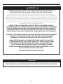
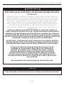
WARNING
IMPROPER USE OR FAILURE TO FOLLOW INSTRUCTIONS CAN RESULT IN
EXPLOSIVE FAILURE CAUSING SERIOUS EYE OR OTHER INJURY.
FOR SAFE USE OF THIS PRODUCT YOU MUST READ AND FOLLOW ALL
INSTRUCTIONS. DO NOT LEAVE SPRAYER IN THE HOT SUN. HEAT CAN CAUSE
PRESSURE BUILD-UP RESULTING IN POSSIBLE EXPLOSION. DO NOT STORE OR
LEAVE SOLUTION IN TANK AFTER USE. ALWAYS WEAR GOGGLES, GLOVES, LONG
SLEEVE SHIRT, LONG PANTS AND FULL FOOT PROTECTION WHEN SPRAYING.
DO NOT ATTEMPT TO MODIFY THIS SPRAYER. REPLACE PARTS ONLY WITH
MANUFACTURER’S ORIGINAL PARTS.
NEVER SPRAY FLAMMABLE, CAUSTIC, ACIDIC, CHLORINE, BLEACH,
PETROLEUM BASED OR OTHER CORROSIVE SOLUTIONS OR HEAT, PRESSURE,
OR GAS PRODUCING CHEMICALS. ALWAYS READ AND FOLLOW CHEMICAL
MANUFACTURER’S INSTRUCTIONS BEFORE USE WITH THIS SPRAYER AS
SOME CHEMICALS MAY BE HAZARDOUS WHEN USED WITH THIS SPRAYER.
ENSURE THE WIRING HARNESS DOES NOT BECOME PINCHED OR DAMAGED
IN ANY WAY. THIS MAY DAMAGE THE PUMP OR CAUSE THE WIRING
HARNESS TO OVERHEAT, RESULTING IN MELT DOWN OR FIRE.
SOME CHEMICALS WILL DAMAGE THE PUMP VALVES IF ALLOWED
TO SOAK UNTREATED FOR A LONG PERIOD OF TIME. ALWAYS FLUSH
THE PUMP WITH WATER AFTER USE. DO NOT ALLOW CHEMICALS
TO SIT IN PUMP FOR EXTENDED TIMES OF IDLENESS. FOLLOW
CHEMICAL MANUFACTURERS INSTRUCTIONS ON DISPOSAL OF ALL
WASTE WATER FROM THE SPRAYER.
USE WATER BASED CHEMICALS ONLY.
CAUTION
THIS SPRAYER HAS BEEN DESIGNED TO BE ATTACHED TO STABLE SURFACES.
Chapin Spot Sprayer Operator’s Manual - English

Chapin Spot Sprayer Operator’s Manual - English
2E
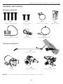
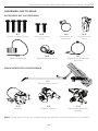
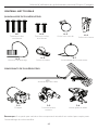
CONTENTS- NOT TO SCALE
H-1
Phillips Head Screw
C-3
External Bypass
H-3
Worm Gear Clamp
H-7
Lead Wire Assembly
H-5
Drain Cap w/ Lanyard
H-6
Loop Clamp
C-1
Wand Assembly
H-2
Phillips Head
Screw
H-4
Wand Clamp
SPRAYER HARDWARE
SPRAYER COMPONENTS
C-2
Pump
C-4
Flow Director Valve
NOTE: not all components shown may be needed on your model.

3E
Chapin Spot Sprayer Operator’s Manual - English
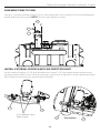
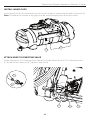
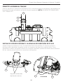
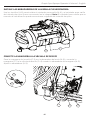
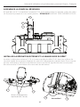
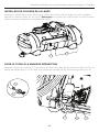
ASSEMBLE PUMP TO TANK
Using H-1 screws, fasten pump (C-2) to face plate with loop clamp (H-6) inserted between
pump and front left screw. NOTE: Do not over-tighten screws.
INSTALL EXTERNAL BYPASS AND FLOW DIRECTOR VALVE
Install external bypass (C-3) and flow director valve (C-4) into pump quick release ports;
engage quick release locks. Note: to ensure a good seal, a tight fit is used; significant hand
force may be necessary to install bypass fittings.
H-1
H-6
C-2
C-4
C-4
C-3
C-3
Quick Release Locks
(open/close)
Assembled

Chapin Spot Sprayer Operator’s Manual - English
4E
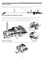
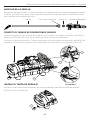
INSTALL WAND CLIPS
Install wand clip (H-4) and wand clip from nylon strap (as shown above) with screws (H-2).
Note: The wand clip shown to the right can be found hanging from the nylon strap.
Guide wand hose (C-1) through loop clamp (H-6) and attach hose (C-1) to diverting valve
(C-4) with hose clamp (H-3). Tighten clamp (H-3).
C-1
H-6
H-6
ATTACH HOSE TO DIVERTING VALVE
C-1
H-3 C-4
H-2
H-4
H-4

5E
Chapin Spot Sprayer Operator’s Manual - English
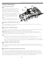
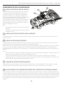
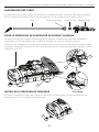
WAND ASSEMBLY
Wand O-ring
Shut-O Valve
Retaining Nut
Make sure the o-ring is installed on the end of the wand. Insert the wand into shut-off valve.
Turn and tighten the retaining nut clock-wise onto the shut-off valve.
ATTACH CHEMICAL CONCENTRATE TANK
Before chemical tank installation, attach supplied rachet straps to strap slots on tank.
Securely fasten assembly to ATV. NOTE: not all models included ratchet straps.
Attach the mix valve’s suction tubing (1) to the chemical concentrate tank’s quick release
port (2). Secure chemical concentrate tank with nylon webbing (3).
Assembled
3
1
2
INSTALL DRAIN CAP
Install cap lanyard around drain plug. Screw drain cap (H-5) on drain plug.
H-5

6E
Chapin Spot Sprayer Operator’s Manual - English
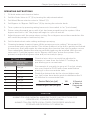
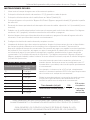
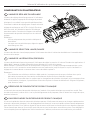
SPRAYER COMPONENTS
4
5
2
3
1
MIX SETTING VALVE
The mix setting valve allows the user to
set the desired chemical mix ratio. It is
calibrated to a specific gravity of water.
See setting chart for each settings mix
value in oz./gal. Due to chemical viscosity,
actual mix ratios may vary. Refer to
chemical’s recommended mix ratios
when choosing what setting to use.
Note:
• Use water based chemicals only.
• When not spraying set mix ratio to zero.
1
WAND / BOOM SELECTOR VALVE
The wand/boom selector valve allows the user to select the flow to either be diverted to
the wand assembly or the boom.
2
BYPASS / PRESSURE VALVE
The bypass/pressure valve allows the user to adjust the wand’s pressure. During low flow
applications it allows flow to be diverted to eliminate pump cycling.
How to use: Start with the valve set to “Bypass off”. When the pump begins to cycle;
between on and off, turn the valve slowly counter clockwise until the cycling stops. The
valve setting should fall in the “optimal” flow region.
Note:
• If the bypass is used beyond the “optimal flow” region the pump may not shut off as
the bypass doesn’t allow it to build enough pressure to turn the pump off.
• If too much air is introduced into the system from changing chemicals or running the
water or chemical tanks dry it may be necessary to switch the bypass valve to “Bypass
off/Prime” in order to prime the unit.
3
CHEMICAL CONCENTRATE TANK
The chemical concentrate tank is where the chemical concentrate is held. To install the
tank, insert the tank onto the faceplate’s alignment feet and secure with the nylon webbing
and snap latch.
4
CHEMICAL TANK QUICK RELEASE COUPLING
The chemical tank quick release coupling allows the user to quickly and cleanly change
out chemical tanks. When disengaged the tank’s quick release automatically closes to
stop spillage. To use, align the male locking pins with the female nut’s slots. Press female
nut over the male nut and turn clockwise to lock in place. To disengage the quick release
coupling, slightly push the female nut in, turn counterclockwise and remove.
5

Chapin Spot Sprayer Operator’s Manual - English
7E
OPERATING INSTRUCTIONS
1. Fill both water and chemical tanks.
2. Set Mix Ratio Valve to “0” (1) by turning the adjustment wheel.
3. Set Wand/Boom selector valve to “Wand” (2).
4. Set Bypass to “Bypass Off/Prime” (3) by turning the selector knob.
5. Turn system on by pressing wiring harness in-line switch to “on” (not shown).
6. Prime: using the wand spray until all air has been purged from the system. If the
bypass was set to “off” the pump will begin to cycle on and off.
7. Adjust bypass until the pump stops cycling. Do not bypass more than needed as this
will cause the pump to continuously run.
8. Set the desired mix ratio setting and begin spraying.
9. Cleaning between chemical types: While spraying on mix setting 7 disconnect the
concentrate tank’s quick release. This allows chemical in the line to quickly be flushed.
If necessary, flush with water by submerging the chemical line into the water source.
Once adequately flushed the new concentrate tank may be installed. With the mix
valve set to 7 and the bypass set to “Bypass off/Prime” prime the system. Once
primed, re-adjust the bypass valve and you’re ready to spray.
CAUTION
ALWAYS FOLLOW CHEMICAL MANUFACTURER’S INSTRUCTIONS FOR
PROPER USE, STORAGE AND DISPOSAL.
ALWAYS FOLLOW STATE/LOCAL CODES FOR PROPER HANDLING,
STORAGE AND DISPOSAL OF CHEMICAL.
SETTING GUIDE
SETTING OUNCE PER
GALLON
0 0 oz/gal
1 1 oz/gal
2 2 oz/gal
3 3 oz/gal
4 4 oz/gal
5 5 oz/gal
6 10 oz/gal
7 15 oz/gal
Chemical mix ratios can easily be adjusted in
between or lower than the listed 0-7 settings by
pre-diluting your concentrate.
For example, if you wish to spray at .5 oz/gal, simply
mix your chemical 50:50 with clean water before
placing it in the concentrate tank.
Divide the desired rate by the closest higher rate
(oz. /gal) value from above guide to determine the %
of chemical in concentrate tank.
Desired Rate (oz./gal)
Closest higher rate (oz./gal)
x
100
1
=
% Chemical
to Water for
Concentrate
Tank

Chapin Spot Sprayer Operator’s Manual - English
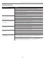
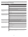
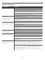
TROUBLESHOOTING
CONDITION CHECK
Pump won’t start Correct voltage (±10%) and electrical connections
Fuse or breaker
Pressure switch operation
Rectifer or motor for open or grounded circuit
Locked drive assembly
Correct voltage at switch
Pump will not prime
(No discharge with motor
running)
Debris in strainer
Restriction (kinks) in inlet / outlet tubes
Debris / swelling in inlet / outlet valves
Bypass is not in “off” position
Pump will not shut-off
(output line closed and
no leaks)
Air trapped in outlet line or pump head
Correct voltage to pump
Debris in pump inlet / outlet valves
Loose drive assembly or pump head screws
Pressure switch operations / adjustments
Leaks from pump head
or switch
Loose screws at switch or pump head
Switch diaphragm ruptured or pinched
Punctured diaphragm if fluid is present
Pump output spits and
sputters
All hose clamps are adequately tight
No holes in tubing
There is adequate liquid in both the water and chemical tank
Adjust external bypass to optimize spray pattern
Pump makes noise, but
no output
Prime with garden hose by removing intake hose and flood with
water while pump is running until water starts flowing (this may
take up to 15 minutes to create suction).
To better understand the priming process see video at: https://www.
youtube.com/watch?v=lrNeAvNL7Fs or search “Priming the Pump on Your
Chapin ATV Sprayer” at Chapin International’s YouTube page.
8E

Chapin Spot Sprayer Operator’s Manual - English
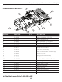
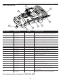
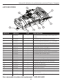
BREAKDOWN & PARTS LIST
REF NO. PART NO. QTY DESCRIPTION
1 6-9138 1 Pump Assembly, 2.5 GPM
2 6-9202 1 Pump Hardware Kit
3 6-8060 1 Tank Assembly, 1.33 Gallon
3 6-8061 1 Tank Assembly, 2.0 Gallon
4 6-8272 1 Faceplate, 15 Gallon
4 6-8273 1 Faceplate, 25 Gallon
5 6-8219 1 Extension Assembly
6 6-8138 1 Shut-Off Assembly, cushion grip
7 6-8093 1 Nozzle Kit, Poly
8 6-9203 1 Suction Hose Assembly
9 6-8321 1 Inlet Strainer
10 6-8146-1 1 Tank Lid & 6 inch Filter Basket
11 6-8325 1 Drain Plug Kit
12 6-8003 2 Worm Gear Clamp
13 6-9204 1 Rubber Grommet
14 6-8324 2 Wand Clip, pair
15 6-8274 1 Wand Clip, Tie Down
16 6-8320 1 Lead Wire Assembly w/ Switch
17 6-9205 1 15’ Hose, Reinforced
6
5
14
7
11
10
1
3
4
17
9E
To Order Replacement Parts: 1-800-950-4458

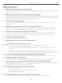
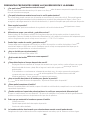
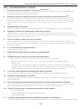
SPRAY & PUMP FAQ
Chapin Spot Sprayer Operator’s Manual - English
1. Why does the pump not run all the time?
This is a demand pump and only runs with flow; a specific pressure must be reached
before the pump turns off.
2. Why does the pump surge while using the spray wand?
Low flow may cause the pump to surge (or cycle). This could happen when the spray
wand is adjusted for a small or fine spray pattern. To overcome, slightly open the by-
pass valve, or adjust the nozzle to allow more flow.
3. How do I adjust the pressure?
Pressure should be adjusted by regulating the by-pass valve (slightly opening or
closing).
4. My pump quit and will not restart - what should I check?
Check all electrical connections. Ensure switch is in the on position. Check in-line
fuse and/or fuse in car adapter end. Ensure correct voltage +/- 10%. 12-14 volt
5. Low flow or no flow at all - what should I check?
Check for a clogged suction hose and/or suction strainer. Often you will need to
clean the suction strainer. Check for proper voltage. Check for crimped hosing.
6. Is there a fuse for the sprayer?
Yes, in-line to the 12V wiring harness.
7. What size fuse should I use as a replacement?
10 amp
8. How should I clean the tank after use?
• Rinse tank thoroughly with water only, empty, refill with water.
• Open shut-off and allow water to run through discharge assembly. Empty
sprayer.
• If the unit is to be stored below freezing the best way to winterize is to run RV
antifreeze through both lines before storage, then purge with water in the spring.
9. Is there an adjustment screw on the pump to adjust pressure?
Yes, please refer to the operation instructions, “Adjusting the Pressure Switch”.
10. How do I remove / replace fuse?
Open fuse housing, remove fuse if blown, replace with equivialently rated fuse.
11. Can the spray tip on the wand be replaced with a different type of tip?
Yes, however your wand comes with a #18 tip which is standard. Brass tips generally
produce better spray patterns than plastic.
12. Each time I turn on the pump my fuse blows.
• Excessive voltage
• Improper adjustment of the pressure switch
• Damaged wiring harness
13. Pump continues to run and surge when not spraying.
Ensure the by-pass is completely closed and your system has no leaks.
10E

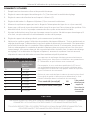
Due to our ongoing product improvement process, product specifications may change without notice. U.S. and foreign patents pending.
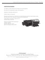
Congratulations!
You have just purchased a quality Chapin product.
Register Your Spreader Online@ www.chapinmfg.com/warranty.asp
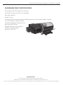
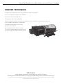
DIAPHRAGM PUMP SPECIFICATIONS
Fits Chapin 15 and 25 gallon ATV sprayers
12 Volt DC, totally enclosed, non ventilated
Max amp rating: 8
Leads: 6” long
2 chamber positive displacement diaphragm pump, self priming, capable of being
run dry, demand or bypass model.
Priming Capabilities: 4 feet [1.2 ml)
Max Pressure: 60 PSI
Inlet/Outlet Ports: Ouick Attach
[2] 3/4” to 3/8” Straight
[1] 3/4” to 3/8” 90’
Chapin Spot Sprayer Operator’s Manual - English

Visite el sitio web para conocer los
detalles de la garantía
Manual de uso y cuidado
DO NOT RETURN TO STORE
Call: 1-800-950-4458
www.chapinmfg.com
PULVERIZADOR PARA ATV
Modelo 97361, 97561
016028 R0121
Chapin International, Inc
P.O. Box 549 700 Ellicott St.
Batavia, NY 14021-0549 U.S.A.
1-800-950-4458 www.chapinmfg.com
Lea estas instrucciones atentamente antes de utilizarlo
ADVERTENCIA
25 Gallon
15 Gallon

1S
ADVERTENCIA
ADVERTENCIA: EL USO INAPROPIADO O NO SEGUIR LAS INSTRUCCIONES PUEDE
DAR LUGAR A UNA FALLA EXPLOSIVA Y CAUSAR SERIAS LESIONES OCULARES O
DE OTRO TIPO.
PARA EL USO SEGURO DE ESTE PRODUCTO, DEBE LEER Y SEGUIR TODAS LAS
INSTRUCCIONES. NO DEJE EL PULVERIZADOR EXPUESTO AL SOL. EL CALOR
PUEDE PROVOCAR UNA ACUMULACIÓN DE PRESIÓN QUE CAUSE UNA POSIBLE
EXPLOSIÓN. NO ALMACENE O DEJE LA SOLUCIÓN EN EL TANQUE DESPUÉS
DE USAR. CUANDO UTILICE EL PULVERIZADOR USE SIEMPRE ANTEOJOS
PROTECTORES, GUANTES, CAMISA DE MANGA LARGA, PANTALONES LARGOS
Y PROTECCIÓN COMPLETA EN LOS PIES. NO INTENTE MODIFICAR ESTE
PULVERIZADOR. REEMPLACE LAS PIEZAS SÓLO CON PIEZAS ORIGINALES DEL
FABRICANTE.
NUNCA PULVERICE SOLUCIONES INFLAMABLES, CÁUSTICAS, ÁCIDAS, DE
CLORO, A BASE DE PETRÓLEO, DE LEJÍA U OTRAS SOLUCIONES CORROSIVAS NI
QUÍMICOS QUE PRODUZCAN CALOR, PRESIÓN O GAS. SIEMPRE LEA Y SIGA LAS
INSTRUCCIONES DEL FABRICANTE DEL PRODUCTO QUÍMICO ANTES DE USARLO
CON ESTE PULVERIZADOR, YA QUE ALGUNOS PRODUCTOS QUÍMICOS PUEDEN SER
PELIGROSOS CUANDO SE USAN CON ESTE PULVERIZADOR.
ADVERTENCIA - ASEGÚRESE DE QUE EL CABLE NO SE PELLIZQUE O DAÑE DE
NINGUNA MANERA. ESTO PODRÍA DAÑAR LA BOMBA O HACER QUE EL CABLE
SE SOBRECALIENTE, DANDO LUGAR A PIEZAS DERRETIDAS O UN INCENDIO.
ALGUNAS SUSTANCIAS QUÍMICAS DAÑARÁN LAS VÁLVULAS DE
LA BOMBA SI SE LES PERMITE REMOJARSE SIN TRATAMIENTO
DURANTE UN PERÍODO LARGO. SIEMPRE ENJUAGUE LA BOMBA
CON AGUA DESPUÉS DE USARLA. NO PERMITA QUE SUSTANCIAS
QUÍMICAS REPOSEN EN LA BOMBA DURANTE PERÍODOS EXTENSOS
DE INACTIVIDAD. SIGA LAS INSTRUCCIONES DEL FABRICANTE DE LA
SUSTANCIA QUÍMICA RESPECTO AL DESECHO DE TODA EL AGUA USADA
DEL ASPERSOR.
USE SOLAMENTE SUSTANCIAS QUÍMICAS CON BASE DE AGUA.
CAUTION
ESTOS ASPERSORES ESTÁN DISEÑADOS PARA SUJETARSE A UNA SUPERFICIE ESTABLE.
Manual del operador del pulverizador de zonas Chapin - Español

2S
Manual del operador del pulverizador de zonas Chapin - Español
CONTENIDO- NOT TO SCALE
H-1
Tornillo de cabeza Philips
C-3
Bypass externo
H-3
Abrazadera de
manguera
H-7
Montaje del conductor
principal
H-5
Tapón de drenaje
H-6
Abrazadera de bucle
C-1
Montaje de la varilla
H-2
Tornillo de cabeza
Philips
H-4
Sujetador para
varilla
ACCESORIOS DEL PULVERIZADOR
COMPONENTES DEL PULVERIZADOR
C-2
Bomba
C-4
Válvula de dirección
de flujo
Nota: Puede que no todos los componentes mostrados sean necesarios en su modelo.

3S
Chapin Spot Sprayer Operator’s Manual - English
CONECTE LA BOMBA AL TANQUE
Use los tornillos H-1 para fijar la bomba (C-2) a la placa frontal, insertando la abrazadera de
bucle (H-6) entre la bomba y el tornillo frontal izquierdo. NOTA: NO APRIETE DEMASIADO
LOS TORNILLOS.
INSTALE EL BYPASS EXTERNO Y LA VÁLVULA DE DIRECCIÓN DE FLUJO
Instale el bypass externo (C-3) y la válvula de dirección de flujo (C-4) en los puertos
de liberación rápida de la bomba; active los seguros de liberación rápida. Nota: Para
garantizar un bien sello debe usarse un conector apretado; puede necesitar mucha fuerza
en las manos para instalar los conectores del bypass.
H-1
H-6
C-2
C-4
C-4
C-3
C-3
Seguros de liberación
rápida (abrir/cerrar)
Assembled

Chapin Spot Sprayer Operator’s Manual - English
4S
INSTALE LAS ABRAZADERAS DE LA VARILLA PULVERIZADORA
Use los tornillos (H-2) para instalar el sujetador para varilla (H-4) y el sujetador para varilla
del cinturón de nylon (como se muestra en la imagen) Nota: El sujetador para varilla que se
muestra al lado derecho puede encontrarse colgando del cinturón de nylon.
Pase la manguera de la varilla (C-1) por la abrazadera de bucle (H-6) y conecte la
manguera (C-1) a la válvula de desvío (C-4) usando la abrazadera de manguera (H-3).
Ajuste la abrazadera (H-3).
C-1
H-6
H-6
CONECTE LA MANGUERA A LA VÁLVULA DE DESVÍO
C-1
H-3 C-4
H-2
H-4
H-4

5S
Manual del operador del pulverizador de zonas Chapin - Español
MONTAJE DE LA VARILLA
Varilla Anillo “O”
Válvula de apagado
Tuerca de retención
Asegúrese de que el anillo “O” esté instalado en el extremo de la varilla pulverizadora. Inserte
la varilla a la válvula de cierre. Gire y apriete la tuerca de retención sobre la válvula de cierre
en el sentido de las agujas del reloj.
CONECTE EL TANQUE DE CONCENTRADO QUÍMICO
Usando las ranuras para correas del tanque y las correas con matraca incluidas, fije bien el
equipo al ATV. Nota: No todos los modelos incluyen correas con trinquete.
Conecte la tubería de succión (1) de la válvula de mezcla al puerto de liberación rápida (2) del
tanque de concentrado químico. Fije el tanque de concentrado con la correa de nylon (3).
Assembled
3
1
2
INSTALE EL TAPÓN DE DRENAJE
Instale el cordón de la tapa alrededor del sello de drenaje. Atornille el tapón de drenaje
(H-5) en el sello de drenaje.
H-5

6S
Manual del operador del pulverizador de zonas Chapin - Español
COMPONENTES DEL PULVERIZADOR
4
5
2
3
1
VÁLVULA DE RELACIÓN DE MEZCLA
La válvula de relación de mezcla permite al usuario
configura la relación deseada para la mezcla de
la sustancia química. Se calibra a una gravedad
específica de agua. Vea la tabla de configuración
para ver el valor de la mezcla de cada configuración
en onzas/galón. Debido a la viscosidad de las
sustancias químicas, las relaciones de mezcla reales
podrían variar. Consulte las relaciones de mezcla
recomendadas para la sustancia química antes de
elegir la configuración a usar.
Nota:
• Use solamente sustancias químicas con base
de agua.
• Cuando no esté pulverizando, ajuste la relación
de mezcla a cero.
1
VÁLVULA DE SELECCIÓN DE VARILLA/BRAZO
La válvula de selección de varilla/brazo permite al usuario seleccionar que el flujo se desvíe al conjunto de la
varilla o al brazo.
2
VÁLVULA DE BYPASS/PRESIÓN
La válvula de bypass/presión permite al usuario ajustar la presión de la varilla. En aplicaciones con bajo flujo,
permite desviar el flujo para evitar que la bomba se encienda y apague.
Instrucciones de uso: Comience con la válvula en la posición “Bypass off” (Bypass apagado). Cuando la bomba
inicie su ciclo de encendido y apagado, gire la válvula lentamente en sentido contrario a las agujas del reloj
entre cada parada hasta que el ciclo se detenga. La configuración de la válvula debe estar en la región de flujo
“óptimo”.
Nota:
• Si se usa el bypass fuera de la región de “flujo óptimo”, la bomba podría no apagarse, ya que el bypass no le
permite acumular suficiente presión para apagar la bomba.
• Si se introduce demasiado aire al sistema al cambiar la sustancia química o dejar que se sequen los
tanques de agua o de sustancia química, quizá sea necesario cambiar la válvula de bypass a “Bypass off/
Prime” (Bypass apagado/cebado) para cebar la unidad.
3
TANQUE DE CONCENTRADO QUÍMICO
El tanque de concentrado químico es en donde se almacena el concentrado químico. Para instalar el tanque,
insértelo sobre las patas de alineación de la placa frontal y fíjelo con la correa de nylon y el seguro.
4
ACOPLAMIENTO DE LIBERACIÓN RÁPIDA DEL TANQUE DE SUSTANCIA QUÍMICA
El acoplamiento de liberación rápida del tanque de sustancia química permite al usuario cambiar de tanque de
sustancia química de manera rápida y limpia. Cuando se desconecta, el conector de liberación rápida del tanque
se cierra automáticamente para evitar derrames. Para usarlo, alinee las clavijas del seguro con las ranuras de la
tuerca. Oprima la tuerca hembra sobre la tuerca macho y gire en sentido horario para fijarlas. Para desconectar
el acoplamiento de liberación rápida, empuje ligeramente la tuerca hembra, gírela en sentido antihorario y
sáquela.
5

7S
Manual del operador del pulverizador de zonas Chapin - Español
INSTRUCCIONES DE USO:
1. Llene tanto el tanque de agua como el de sustancia química.
2. Coloque la válvula de relación de mezcla en “0” (1) girando la rueda de ajuste.
3. Coloque la válvula selectora de la varilla/brazo en “Wand” (Varilla) (2).
4. Coloque el bypass en la posición “Bypass Off/Prime” (Bypass apagado/cebado) (3) girando la perilla
de selección.
5. Encienda el sistema oprimiendo el interruptor del mazo de cables a lposición “on” (encendido) (no se
muestra).
6. Cebado: use la varilla pulverizadora hasta que se haya purgado todo el aire del sistema. Si el bypass
estaba en “off” (apagado), la bomba comenzará a encenderse y apagarse.
7. Ajuste el bypass hasta que la bomba deje de encenderse y apagarse. No abra el bypass más de lo
necesario, o hará que la bomba funcione constantemente.
8. Configure la relación de mezcla deseada y empiece a rociar.
9. Limpieza de distintos tipos de sustancias químicas: Limpie el sistema antes de usar un tipo distinto
de sustancia química: Mientras está rociando en la configuración de mezcla 7, desconecte la
liberación rápida del tanque de concentrado. Esto permite enjuagar con rapidez la sustancia química
de la tubería. Si es necesario, enjuague con agua, sumergiendo la tubería de la sustancia química
en la fuente de agua. Una vez que se enjuague por completo, puede instalar el nuevo tanque de
concentrado. Con la válvula de mezcla en la posición 7 y el bypass en posición “Bypass off/prime”
(Bypass apagado/cebado), cebe el sistema. Una vez cebado el sistema, reajuste la válvula de bypass
y estará listo para rociar.
CAUTION
SIGA SIEMPRE LAS INSTRUCCIONES DEL FABRICANTE SOBRE EL USO,
ALMACENAMIENTO Y ELIMINACIÓN ADECUADOS DEL PRODUCTO QUÍMICO.
SIGA SIEMPRE LOS CÓDIGOS LOCALES/ESTATALES PARA EL USO,
ALMACENAMIENTO Y ELIMINACIÓN ADECUADOS DE LOS QUÍMICOS.
GUÍA DE CONFIGURACIÓN
CONFIGURACIÓN ONZAS POR
GALÓN
0 0 oz/gal
1 1 oz/gal
2 2 oz/gal
3 3 oz/gal
4 4 oz/gal
5 5 oz/gal
6 10 oz/gal
7 15 oz/gal
Las relaciones de mezcla de sustancias químicas se
pueden ajustar fácilmente entre las configuraciones 0-7
enumeradas o por debajo de ellas diluyendo previamente
el concentrado.
Por ejemplo, si desea rociar a 0.5 oz/gal, simplemente
mezcle su sustancia química 50:50 con agua limpia antes
de colocarla en el tanque de concentrado.
Divida la tasa deseada por la tasa más alta más cercana
(oz/gal) de la guía anterior para determinar el % de
sustancia química en el tanque de concentrado.
Tasa deseada (oz/gal)
Tasa más alta cercana (oz/gal)
x
100
1
=
% De sustan-
cia química
a agua para
tanque de
concentrado
La page est en cours de chargement...
La page est en cours de chargement...
La page est en cours de chargement...
La page est en cours de chargement...
La page est en cours de chargement...
La page est en cours de chargement...
La page est en cours de chargement...
La page est en cours de chargement...
La page est en cours de chargement...
La page est en cours de chargement...
La page est en cours de chargement...
La page est en cours de chargement...
La page est en cours de chargement...
La page est en cours de chargement...
La page est en cours de chargement...
La page est en cours de chargement...
-
 1
1
-
 2
2
-
 3
3
-
 4
4
-
 5
5
-
 6
6
-
 7
7
-
 8
8
-
 9
9
-
 10
10
-
 11
11
-
 12
12
-
 13
13
-
 14
14
-
 15
15
-
 16
16
-
 17
17
-
 18
18
-
 19
19
-
 20
20
-
 21
21
-
 22
22
-
 23
23
-
 24
24
-
 25
25
-
 26
26
-
 27
27
-
 28
28
-
 29
29
-
 30
30
-
 31
31
-
 32
32
-
 33
33
-
 34
34
-
 35
35
-
 36
36


Chapin 97561 Manuel utilisateur
- Taper
- Manuel utilisateur
dans d''autres langues
- español: Chapin 97561 Manual de usuario
Documents connexes
-
Chapin 7-6009 Manuel utilisateur
-
-
Chapin 97300E Manuel utilisateur
-
Chapin 97200E Manuel utilisateur
-
Chapin 97300 spécification
-
Chapin 63900 Information produit
-
-
-
Chapin 60100 Manuel utilisateur
-
Chapin 61813 Manuel utilisateur