
TECHNICAL SERVICE AND PARTS ASSISTANCE - US: 1-800-814-2028 | CANADA: 1-800-444-4764
For additional information, or to locate an authorized parts and service provider in your area, visit wolfequipment.com
Wolf is a division of ITW Food Equipment Group | 3600 North Point Blvd., Baltimore, MD 21222
F51058 Rev. C (10/30/2023)
INSTALLATION &
OPERATION MANUAL
ELECTRIC CONVECTION OVENS
MODELS: WC4E

–2 –
Installation, Operation and Care of
ELECTRIC CONVECTION OVENS
KEEP THESE INSTRUCTIONS FOR FUTURE USE
Your Electric Convection Oven is produced with quality workmanship and material. Proper installation,
usage and maintenance of your oven will result in many years of satisfactory performance.
The manufacturer suggests that you thoroughly read this entire manual and carefully follow all of the
instructions provided.
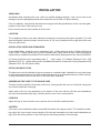
GENERAL
The Electric Convection Ovens feature a 500°F thermostat, timer, porcelain interior and a two -speed, 1/2
HP blower motor as standard equipment. Ovens equipped with standard voltages are 208 or 240 V, 60
Hz, single- or three-phase.
The Oven is a single cavity oven furnished with flve racks. Simultaneous chain driven 50/50 doors with
double pane windows are standard. Oven lights with on-off switch are standard on all models.
An open stand with lower storage rack is available as an option.
Stacked ovens are furnished with either Stacking Kit 426983G1 (8" LEGS) or Stacking Kit 426984G1
(CASTER) for mounting one oven on top of the other.
Additional racks are available as accessories.
Features of the models are shown below:

–3 –
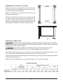
INSTALLATION
UNPACKING
Immediately after unpacking the oven, check for possible shipping damage. If the oven is found to be
damaged, save the packaging material and contact the carrier within 15 days of delivery.
Prior to installation, verify that the electrical service agrees with the speciflcations on the oven data plate,
located on the inside of the top front cover.
Do not use the doors or their handles to lift the oven.
LOCATION
The installation location must allow adequate clearances for servicing and proper operation. For solid
state and digitally controlled models, there must be 18" (45 cm) of clearance on the right side of the oven
from any open ‡ame.
INSTALLATION CODES AND STANDARDS
In the United States, install the oven in accordance with: 1) State and local codes; 2) National Electrical
Code, NFPA-70 (latest edition) and 3) NFPA Standard #96, Vapor Removal from Cooking Equipment
(latest edition), available from National Fire Protection Association, Batterymarch Park, Quincy, MA 02269.
In Canada, install the oven in accordance with: 1) Local codes; 2) Canadian Electrical Code, CSA
Standard C22.2 No. 1 (latest edition) and 3) Canadian Standard for Commercial Cooking Equipment CSA
Standard C22.2 No.109 (latest edition).
INSTALLING BASIC OVEN
The basic oven must be installed on legs or mounted on a modular stand. Installations on concrete bases
or other supports restricting air circulation underneath the oven is not advisable and may void the warranty.
If using the modular stand, set the oven on the stand after unpacking.
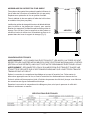
ASSEMBLING THE LEGS TO THE SINGLE OVEN
The legs must be installed on the bottom of the oven. Gently position the oven on its left side, taking care
not to cause scratches or damage.
Attach each of the four leg assemblies to the bottom of the oven with the 24 bolts and lockwashers
(six bolts and lockwashers per leg). Carefully raise the oven to its normal position.
LEVELING
Adjust the legs to ensure that the oven racks are level in the final installed position.
CASTERS
If the oven is to be installed on casters, assemble the casters to the legs provided. Then attach the caster-
leg units to the oven at each corner using the 24 bolts and lockwashers (six bolts and lockwashers per
leg). Place the locking casters on the front legs and nonlocking casters on the rear legs.

–4 –
Fig. 2
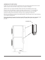
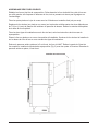
ASSEMBLING THE STAND TO THE OVEN
Attach each of the four leg assemblies to the bottom of the
oven with the 24 bolts and lockwashers (six per leg). Carefully
raise the oven to the normal position.
Attach the undershelf to the legs with eight bolts and
lockwashers (two per leg).
Install the rack guides into the shelf at the desired locations
(for pans or racks), then attach the rack supports to the
top end of the rack guides. Attach rack supports to the leg
assembly by removing one middle bolt and reattaching the
back through the end holes in the rack support (Fig. 2).
ELECTRICAL CONNECTIONS
BACK
FRONT
PL-53274
ELECTRICAL AND GROUNDING CONNECTIONS MUST COMPLY WITH THE APPLI
CABLE PORTIONS OF THE NATIONAL ELECTRICAL CODE ANSI/NFPA70 (LATEST EDITION) AND/OR
OTHER LOCAL ELECTRICAL CODES.
DISCONNECT ELECTRICAL POWER SUPPLY AND PLACE A TAG AT THE
DISCONNECT SWITCH TO INDICATE THAT YOU ARE WORKING ON THE CIRCUIT.
Remove the wiring compartment cover on the front of the oven. Remove the appropriate knockout on the
bottom of the oven and attach the power supply conduit to the bottom of the oven.
Comply with the appropriate wiring diagram (located inside the right side panel) when making connections
to the electrical supply lines.
Replace the wiring compartment cover and right side panel. Turn on the power supply.
ELECTRICAL DATA

–5 –
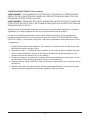
ASSEMBLING STACKED OVENS
Unpack the ovens and the stack kitV. Position the oven to be used as the bottom oven on its left
sidefor access to the oven bottom, taking care not to scratch or damage it.
Attach the four leg RUFDVWHUassemblies with the 24 bolts and lockwashers (six per leg).
Place the lower oven (with legsRUFDVWHUV) on the floor and remove two 7/16" (11 mm) diameter
knockouts on eachside of the top H[WHULRUSDQHO.5HPRYHNQRFNRXWIURPWRSRYHQEDVH
Install two locating studs to the bottom of the top oven per stacking kit instructions.
Move the oven with legs RUFDVWHUVto the installed position. Place the upper oven on top of the lower
oven usingthe locating studs.
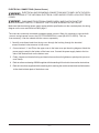
Remove the optional rear panel, if provided, from the TOP oven. 5HPRYHWRSRYHQYHQWJXDUGInstall
the Stacking Flue (Fig. 3) withthe four screws provided. Replace the top oven rear panel, if
provided.
STACKING FLUE

–6 –
ELECTRICAL CONNECTIONS (Stacked Ovens)
ELECTRICAL AND GROUNDING CONNECTIONS MUST COMPLY WITH THE APPLI
CABLE PORTIONS OF THE NATIONAL ELECTRICAL CODE AND/OR OTHER LOCAL ELECTRICAL
CODES.
DISCONNECT ELECTRICAL POWER SUPPLY AND PLACE A TAG AT THE
DISCONNECTSWITCH TO INDICATE THAT YOU ARE WORKING ON THE CIRCUIT.
Make sure that the electrical power supply agrees with the specifications on the oven data plate, the wiring
diagram on the oven and Electrical Data, page 5.
1. Carefully route these leads from the topoven through the bushing through the electrical
access knockoutholes common to both ovens.
Connect wires X, Y and Z from the upper oven to the lower oven per the wiring diagram. Attach the
power supply conduit to the bottom of the lower oven. Connect the powersupply leads to the line
side of the terminal block on the bottom oven.
Finally, inspect and check all wiring and terminal connections for tightness or pinch points (cover on
oven frame).
Refer to reference drawing 426986 supplied with the stacking kit for electrical connection instructions.
Refer to instructions supplied with the stacking kit for marking the combined electrical load information
to the electrical data plate of the bottom oven.
The ovens are commonly connected to separate power sources. When it’s necessary to connect both
ovens to a single power source, the VCE-STACKWIRES kit is used (00-961571-000G1). This is a
free accessory. It can be ordered with the ovens or separately.

–7 –
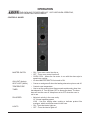
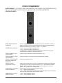
OPERATION
MASTER SWITCH – ON - Turns oven control circuits on.
– OFF - Turns oven control circuits off.
– OVEN COOL - Allows the fan motor to run with the doors ajar to
speed oven cooling.
ON LIGHT (Amber) – Lit when MASTER SWITCH is turned to ON.
HEAT LIGHT (White) –Comes on and goes off when the heating elements cycle on and off.
TEMPERATURE – Controls oven temperature.
TIMER – Use to set the cooking time. Alarm sounds continuously when time
has elapsed to 0. Turn the timer OFF to silence the alarm. The timer
does not turn the oven off. Keep timer set to OFF when the oven is
not in use.
FAN SPEED – Adjust air velocity in the oven cavity.
HI - Normal operating speed.
LOW - Use this setting when cooking a delicate product like
meringue, which could blow around in the oven.
LIGHTS – ON - Turns the interior lights on.
– OFF - Turns the interior lights off.
THE OVEN AND ITS PARTS ARE HOT. USE CARE WHEN OPERATING,
CLEANING OR PERFORMING ANY MAINTENANCE.
CONTROLS : WC4ED

–8 –
BEFORE FIRST USE (All Models)
Before using the oven for the flrst time, it must be burned off to release any odors that might result from
heating the new surfaces in the chamber.
1. Using a clean damp cloth, wipe the inside of the oven, including the racks.
2. Close the oven doors, turn the MASTER SWITCH to ON, turn the Thermostat to 300°F (149°C) and
allow the oven to cycle for 6 to 8 hours before turning the MASTER SWITCH to OFF.
USING ELECTRICAL MODELS
Preheating
1. Turn MASTER SWITCH to ON. Amber ON light will come on, indicating that power to oven is on.
2. Set Thermostat as desired. Refer to COOKING GUIDELINES for suggested temperatures and times
for various products.
3. Prepare product and place in suitable pans. When white HEAT light goes off, oven has reached
desired preheat temperature.
Cooking
1. Open doors and load the product into the oven. Place pans in the center of the racks. Close doors.
2. Set the Timer. After the preset time lapses, turn Timer to OFF position to stop alarm.
3. When product is done, open doors and carefully remove cooked product from the oven. Care should
be taken when wiping up any spills, as oven is still hot.
End of Day
1. Turn Thermostat to lowest setting.
2. Turn MASTER SWITCH to OVEN COOL. Leave doors open while the fan is on to cool the oven.
3. When oven has cooled sufflciently, turn MASTER SWITCH to OFF and clean the oven.

–9 –
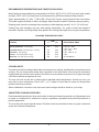
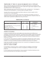
RECOMMENDED TEMPERATURES AND TIMES FOR ROASTING
Meat roasting is most satisfactory at temperatures of 225 to 325°F (107 to 163°C) for beef, lamb, poultry
and ham; 325°F (163°C) for fresh pork as recommended by USDA and American Meat Institute.
A pan, approximately 12 x 20 x 1‘ (305 x 508 x 25 mm) full of water, may be placed in the oven bottom.
This water supplies humidity to reduce shrinkage. Water should be added if necessary during roasting.
Roasting pans should be no deeper than necessary to hold drippings (usually 2 to 21/2‘ (51 to 64 mm).
Cooking time and shrinkage may vary with roasting temperature, cut, grade of meat and degree of
doneness. Smaller cuts will generally show greater time savings than larger cuts at a given temperature.
ROASTING TEMPERATURE CHART
TEMP
PRODUCT °F (°C) APPROXIMATE TIMES
250 (121)
275 (135)
300 (149)
300 (149)
Standing Rib Roast “ Oven Ready
Rolled Rib Roasts “ 20 to 22 lb (9.1 to 10 kg)
Veal Roast “ 15 lb (6.8 kg)
Turkeys “ 15 to 20 lb (6.8 to 9.1 kg)
Meat Loaf “ 8 to 10 lb (3.6 to 4.5 kg) 350 (177)
3 to 4 Hrs. “ Rare
4 to 41/2 Hrs. — Med.
4 Hrs. “ Med.
3 Hrs. “ Med. W ell
3 Hrs.
45 to 60 Minutes
COOKING HINTS
Forced air convection cooking is faster than conventional oven cooking, and therefore overcooking is more
common. Do not cook products faster than is practical for the best results. Since forced air convection
supplies heat to the surface of the product, the thicker or more massive a product is for its type, the longer
it will take to absorb enough heat to cook.
The oven will cook or bake full or partial loads at standard recipe temperatures. As with any oven, you
may wish to use a temperature of up to 25 F° (-4 C°) higher or lower than the recipe for the particular
product result that you prefer.
When established, convection oven times and control settings should be noted on your recipe.
SUGGESTED COOKING GUIDELINES
Recommended temperatures, times and number of racks are intended as a guide only. Adjustments must
be made to compensate for variations in recipes, ingredients, preparation and personal preference in
product appearance.
The oven does not require special recipes. Excellent results can be obtained from any good commercial
recipe with reduced cooking times.

–10 –
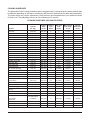
COOKING GUIDELINES
The information in the Cooking Guidelines chart is suggested only. Cooking times for various products may
be different depending on the brand, consistency and the chef’s preferences for taste and presentation.
The times below may require adjustments. Note the times and temperatures of your preferred results
for future use. The preheating time for all of the following is 15 minutes.
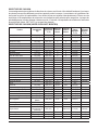
COOKING GUIDELINES (HOLDING FEATURE)
Cooking Cooking Min. Hold Max. Internal Internal
Amount Temp. Time Time Cook Temp. Hold Temp.
Product lbs. (kg) °F (°C) Hours Hours °F (°C) °F (°C)
Prime Rib 20 (9.06) 225 (107) 5 4 140 (60)
Rib Eye Boneless 12 (5.43) 225 (107) 3 4 140 (60)
Top Round 20 (9.06) 225 (107) 5 4 140 (60)
Steamship Round 20 (9.06) 225 (107) 7 2 140 (60)
Bottom Round 20 (9.06) 225 (107) 5 8 140 (60)
Boneless Strip Loin 12 (5.43) 225 (107) 3 4 140 (60)
Whole Tenderloin 6 (2.71) 225 (107) 2 2 140 (60)
Top Sirloin Butt 14 (6.34) 225 (107) 3 4 140 (60)
Beef Short Ribs 10 (4.53) 225 (107) 4 4 165 (74)
Cube Steaks 10 (5.43) 225 (107) 3 3 180 (82)
Beef Back Ribs 30 (13.6) 225 (107) 5 4 175 (79)
Beef Stew 10 (5.43) 225 (107) 4 6 175 (79) 150 (66)
Corned Beef 12 (5.43) 250 (121) 4 4 165 (74) 150 (66)
Fresh Ham 12 (5.43) 250 (121) 6 4 165 (74)
Cooked Cured Ham 12 (5.43) 250 (121) 4 4 135 (57)
Pork Back Ribs 10 (4.53) 250 (121) 5 3 175 (79) 150 (66)
Pork Spare Ribs 30 (13.6) 250 (121) 5 4 175 (79) 150 (66)
Fresh Sausages 10 (4.53) 225 (107) 2 5 (Max) 175 (79)
Pre-Cooked Sausage 10 (4.53) 250 (121) 13/4 51/2 (Max) 160 (71)
Roast Suckling Pig 30 (13.6) 250 (121) 6 3 170 (77) 155 (68)
Bacon 350 (177) 40 min. N/A
Roasted Chicken 10 (4.56) 350 (177) 45 min. N/A 165 (74)
Chicken Pieces (per tray) 10 (4.56) 250 (121) 21/2 1/2 (Max) 170 (77) 150 (66)
Whole Chickens
(per chicken) 3.25 (1.47) 250 (121) 21/2 41/2 (Max) 170 (77) 140 (60)
Whole Turkeys 20 (9.06) 230 (110) 61/2 12 (Max) 170 (77) 160 (71)
Bone In Turkey Breast 10 (4.53) 250 (121) 5 1 160 (71) 150 (66)
Roast Duckling (per duck) 4 (1.81) 350 (177) 11/2 3 (Max) 170 (77) 150 (66)
Rack of Lamb 15 racks 250 (121) 31/2 21/2 160 (71)
per tray
Lamb Shanks, Braised 250 (121) 4 4 180 (82) 150 (66)
Fish Filets 4-6 oz. (23g) 225 (107) 40 min. 4 160 (71)
1/1 Gastronome
Clear Soups or 12x20x4" 225 (107) 3 Overnight 175 (79) 150 (66)
Steam Pan
Frozen Pizza (2) 18” Pies 350 (177) 15 min. 2 175 (79) 160 (71)
Rice 1 Qt. dry 250 (121) 2 18 160 (171) N/A
Baked Potatoes 90 CT. 350 (177) 1 11/2 200 (93) 170 (77)

–11 –
POWER OUTAGE
In case of a power outage, the oven will automatically shut down. When power is restored to the lines, the
oven will resume its normal operation. However, if the oven is to be left unattended during a power outage,
push the MASTER SWITCH to the OFF position. When power is restored to the lines, push MASTER
SWITCH to the ON position, wait for the oven to preheat, then resume normal cooking operations.
CLEANING
WARNING: DISCONNECT ELECTRICAL SUPPLY AND PLACE A TAG AT THE DISCONNECT SWITCH
TO INDICATING THAT YOU ARE WORKING ON THE OVEN BEFORE CLEANING.
• Clean outside of the oven daily by wiping with a clean, damp cloth.
• Clean porcelain oven interior daily with soap or detergent and water. Rinse thoroughly and wipe dry
with a soft, clean cloth.
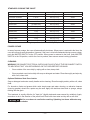
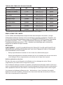
STANDARD COOKING TIME CHART
Product Amount Temp. Time
Frozen Croissant Dough 1.75 oz. 350°F (177°C) 25 Min
Cinnamon Croissant 1.75 oz. 350°F (177°C) 35 Min.
Small Bread Loaves 1 Tray 350°F (177°C) 30 Min.
Large Bread Loaves 1.5 lbs. 350°F (177°C) 60 Min.
Sheet Cake (1) 18x26" Tray 300°F (149°C) 25 Min.
Scone Mix 1 Tray 350°F (177°C) 30 Min.
Muffln Mix 1 Tray 350°F (177°C) 30 Min.
Kaiser Rolls 1 Tray 350°F (177°C) 16 Min.
Italian Bread 1 Tray 350°F (177°C) 40 Min.
Danish Rounds* 1 Tray 350°F (177°C) 30 Min.
Cream Cake* 1 Tray 350°F (177°C) 60 Min.
Cookies 1 Tray 325°F (163°C) 16 Min.
*The maximum internal cooking temperature should be 190°F (88°C).
Optional Stainless Steel Oven Interior
Soap or detergent and water usually handle routine cleaning. Rinse thoroughly and dry with a soft, clean
cloth.
For burned-on foods and grease which resist simple soap and water cleaning, an abrasive cleanser
(scouring powder) mixed into a paste may be used. Apply with stainless steel wool or sponge, always
rubbing with the grain.
This treatment is equally effective for "heat tint" (slightly darkened areas caused by oxidation). Again,
remember to rub in the direction of the polish lines. Rinse with clear water and dry with a soft cloth.
Wait for oven doors to cool before washing. Splashing hot doors with water may
cause the glass to shatter.

–12 –
SERVICE AND PARTS INFORMATION
To obtain service and parts information concerning your Oven, contact the Wolf Service Depot in
your area (refer to listing supplied with this oven) or Wolf Company Service Department at the address
or phone number shown on the front cover of this manual.
MAINTENANCE
the oven.
5(3/$&,1*6,'(02817('/$036
procedures.
LUBRICATION
The fan motor comes with sealed bearings and requires no lubrication.
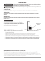
VENT
Periodically check the flue, when the oven is cool, to be sure it is free of obstructions.
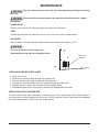
$,5,17$.(
5HDUDLULQWDNHVORWVDQGKROHVVKRXOGEHFOHDQHGZLWKDGDPSFORWKUHJXODUO\),*
The UHDUDLULQWDNHVPXVWEHNHSWFOHDU
1RQFRPSOLDQFHPD\OHDGWRFRPSRQHQWIDLOXUH
Fig.
5($5$,5
,17$.(
$OORZRYHQWRFRRO
5HPRYHDOOUDFNVE\SXOOLQJIRUZDUGOLIWLQJXSDQGRXW
5HPRYHWKHULJKWUDFNJXLGHE\OLIWLQJXSDQGSXOOLQJRXW
3U\JODVVFRYHURIIE\VOLGLQJDIODWWRROXQGHUWKHERWWRPOLSRIWKHFRYHU
5HSODFHWKHEXOE*ORYHVVKRXOGEHZRUQZKLOHKDQGOLQJEXOEV
5HDVVHPEOHJODVVFRYHUDQGUDFNVE\UHYHUVLQJWKHGLVDVVHPEO\SURFHGXUH
The oven and its parts are hot. Use care when operating, cleaning or servicing
Disconnect the electrical power to the machine and follow lockout / tagout

–13–
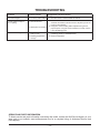
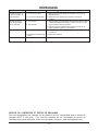
TROUBLESHOOTING
SERVICE AND PARTS INFORMATION
To obtain service and parts information concerning this model, contact the Wolf Service Agency in your
area (refer to our website, www.wolfequipment.com for a complete listing of Authorized Service and
Parts depots).
FORM 51058 Rev. B (09/01/2023)PRINTED IN U.S.A.
Problem Possible Cause Suggested Corrective Action
Uneven browning or
overcooked edges.
1. Oven is too hot.
2. Too many racks used.
1. Reduce temperature setting (refer to Cooking Guidelines).
2. Use fewer racks to allow for better circulation.
1. Level oven racks- side to side and front to back. The rack
should be level side to side and level to 1/8"(3mm) low at the
front from front to back.
2. Keep pans used for baking batter separate from general
purpose pans. If any pan shows a tendency to warp, remove
it from the baking group.
1. Oven is not level.
2. Sheet pans are warped.
1. Failure to maintain
water in oven.
2. Roasting temperature
too high.
1. Place pan of water in bottom of oven
measuring 12x20x1" (305x508x25mm).
2. Reduce temperature.
Excessive shrinkage.
Product pulling to edge of
pan or spilling

SERVICE ECHNIQUE ET ASSISTANCE PIÈCES - US: 1-800-814-2028 | CANADA: 1-800-444-4764
Pour plus d'informations ou pour localiser un fournisseur de pièces et de services agréé dans votre région, visitez wolfequipment.com
Wolf est une division du groupe
iTW ÉQUIPEMENT ALIMENTAIRE
| 3600 North Point Blvd., Baltimore, MD 21222
F51058 Rév. C (30/10/2023)
MANUEL D'INSTALLATION
ET D'UTILISATION
FOURS À CONVECTION ÉLECTRIQUES
MODÈLES:
WC4E

–2 –
INSTALLATION, UTILISATION ET ENTRETIEN DES
FOURS À CONVECTION ÉLECTRIQUES
CONSERVEZ CES INSTRUCTIONS POUR USAGE FUTUR
Votre four à convection électrique est fabriqué avec des matériaux et une main d'œuvre de qualité . Votre
four vous procurera plusieurs années d'utilisation performante dans la mesure où il est installé, utilisé et
entretenu correctement .
Le manufacturier suggère de lire attentivement ce manuel en entier, et de suivre rigoureusement toutes
les directives fournies .
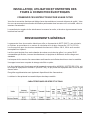
RENSEIGNEMENTS GÉNÉRAUX
La gamme de fours à convection électriques offre un thermostat de 500oF (260oC), une minuterie,
un intérieur en porcelaine et un moteur de circulation d'air à deux vitesses de 1/2 CV (375 W) .
Les fours prévus pour des tensions standards fonctionnent à 208 ou 240 V, 60 Hz avec courant
monophasé ou triphasé .
Les fours sont équipés d'une seule chambre de cuisson munie de cinq grilles. Les portes 50/50
commandées par chaîne, s'ouvrant simultanément, et équipées de fenêtres à double vitrage sont
standards.
Les lampes de four munies d'un commutateur arrêt-marche sont offertes de série sur tous les modèles .
Un support ouvert avec un poste de storage est offert en option .
Les fours doubles sont fournis avec soit la trousse de superposition 426983G1 (PATTES DE 8 PO), soit
la trousse de superposition 426984G1 (ROULETTES), ce qui permet de superposer deux fours l'un par
dessus l'autre .
Des grilles supplémentaires sont également disponibles à titre d'accessoires .
Le tableau ici-bas présente les caractéristiques de chaque modèle :
CARACTÉRISTIQUES DE SÉRIE ET OPTIONS

–3 –
INSTALLATION
DÉBALLAGE
Aussitôt le four retiré de son emballage, inspectez-le afin de repérer tout dommage possiblement subi
lors de l'expédition . Si le four est endommagé, conservez les matériaux d'emballage et contactez le
transporteur dans les 15 jours suivant la livraison .
Avant l'installation, assurez-vous que votre alimentation électrique respecte les spécifications indiquées
sur la plaque signalétique du four, située à l'intérieur du haut du panneau avant .
N'utilisez pas les portes ou les poignées de porte pour soulever le four .
EMPLACEMENT
L'emplacement choisi pour l'installation doit permettre des dégagements suffisants pour l'entretien
et pour une utilisation correcte . Pour les modèles à semi-conducteurs et les modèles à contrôles
numériques, il doit y avoir un dégagement minimal de 18 po (45 cm) du côté droit du four, afin de
l’isoler de toute flamme nue.
RÈGLEMENTATION ET CRITÈRES D'INSTALLATION
Aux États-Unis, vous devez installer le four en respectant : 1) les règlementations de l'état et de la
municipalité ; 2) le National Electrical Code, NFPA-70 (édition la plus récente) ainsi que le standard
NFPA #96, Vapor Removal from Cooking Equipment (édition la plus récente), qui sont disponibles
auprès de la National Fire Protection Association, Batterymarch Park, Quincy, MA 02269 .
Au Canada, vous devez installer le four en respectant : 1) les ordonnances locales ; 2) le Code
Canadien de l'Électricité, standard ACNOR C22 .2, no 1 (édition la plus récente), ainsi que 3) le
Standard Canadien pour les appareils de cuisson commerciale, standard ACNOR C22 .2 no . 109
(édition la plus récente) .
INSTALLATION DE BASE DU FOUR
Le four de base doit être installé sur des pattes, ou monté sur un support modulaire. Il n’est pas
recommandé d’installer le four sur une base de béton ou tout autre type de support qui limite la
circulation d'air sous le four ; ce type d’installation peut même invalider votre garantie. Si vous utilisez le
support modulaire, déposez-y le four une fois celui-ci sorti de son emballage .
FIXATION DES PATTES DU FOUR SIMPLE
Les pattes doivent être installées sous le four . Faites basculer doucement le four sur son côté gauche,
en faisant attention de ne pas l'égratigner ou l'endommager .
Fixez chacune des quatre pattes à la partie inférieure du four à l'aide des 24 boulons et rondelles
frein (six boulons et six rondelles frein par patte) . Soulevez le four avec précaution pour le remettre en
position normale .
MISE À NIVEAU
Ajustez les pattes pour vous assurer que les grilles du four sont à niveau dans sa position finale
d'installation .
ROULETTES
Si le four doit être installé sur des roulettes, fixez d'abord les roulettes sur les pattes fournies. Ensuite,
fixez les blocs pattes-roulettes sous le four à chacun des coins, à l'aide des 24 boulons et rondelles
frein (six boulons et six rondelles frein par patte) . Fixez les roulettes avec verrou sur les pattes avant, et
les roulettes sans verrou sur les pattes arrière .

–4 –
ASSEMBLAGE DU SUPPORT DU FOUR SIMPLE
Fixez chacun des quatre blocs pattes à la partie inférieure du
four à l’aide des 24 boulons et rondelles frein (six par patte).
Replacez avec précaution le four en position normale .
Fixez la tablette du bas aux pattes à l’aide des huit boulons
et rondelles frein (deux par patte) .
Installez les guides de storage à la hauteur de tablette désirée
(pour les bacs ou les plaques de cuisson), pour ensuite
attacher les supports à l’extrémité supérieure des guides de
storage. Pour ce faire, fixez les supports au bloc pattes en
retirant un boulon du milieu et en le remettant en place en le
passant dans les trous du support de storage (Fig . 2) .
CONNEXIONS ÉLECTRIQUES
AVERTISSEMENT : LES CONNEXIONS ÉLECTRIQUES ET LES MISES À LA TERRE DOIVENT
RESPECTER LES CHAPITRES APPLICABLES DU CODE ÉLECTRIQUE NATIONAL ANSI, LE NFPA70
(ÉDITION LA PLUS RÉCENTE), AINSI QUE TOUTE AUTRE ORDONNANCE ÉLECTRIQUE LOCALE .
AVERTISSEMENT : DÉCONNECTEZ LE BLOC D’ALIMENTATION ÉLECTRIQUE ET PLACEZ UNE
ÉTIQUETTE DE SÉCURITÉ SUR LE SECTIONNEUR INDIQUANT QUE VOUS ÊTES EN TRAIN DE
TRAVAILLER SUR LE CIRCUIT .
Retirez le couvercle du compartiment de câblage se trouvant à l’avant du four. Faites sauter la
débouchure appropriée sous le four, et fixez le conduit du bloc d’alimentation au dessous du four.
Suivez le schéma d’interconnexion (situé à l’intérieur du panneau du côté droit) lorsque vous effectuez
les connexions aux lignes d’alimentation électrique.
Remettez le couvercle du compartiment de câblage en place, ainsi que le panneau du côté droit .
Mettez le sectionneur en marche .
BACK
FRONT
PL-53274
ARRIÈRE
AVANT
Fig. 2
SPÉCIFICATIONS ÉLECTRIQUES

–5 –
ASSEMBLAGE DES FOURS DOUBLES
Déballez les fours et les kits de superposition . Faites basculer le four destiné à être celui du bas sur
son côté gauche, afin d’exposer le dessous du four, tout en prenant soin de ne pas l’égratigner ou
l’endommager.
Fixez les quatre pieds ou le jeu de roues avec les 24 boulons et rondelles frein (six par roue) .
Replacez le four du bas (sur pieds ou sur roues) sur le plancher et faites sauter les deux débouchures
de 7/16 po (11 mm) de chaque côté extérieur du panneau de dessus . Retirez les entrées défonçables
de la base du four supérieur .
Fixez les deux tiges de localisation sous le four du haut, selon les instructions de la trousse de
superposition .
Placez le four sur pieds ou sur roues à sa position d’installation. Soulevez le four du haut et installez-le
sur le dessus du four du bas en vous servant des tiges de localisation .
Enlevez le panneau arrière optionnel, s'il est fourni, du four du HAUT. Retirez le garde de l’évent du
four supérieur . Installez la cheminée de superposition (Fig . 3) avec les quatre vis fournies . Remettez le
panneau arrière en place, s'il est fourni .
Fig. 3
CHEMINÉE DE SUPERPOSITION

–6 –
CONNEXIONS ÉLECTRIQUES (fours doubles)
AVERTISSEMENT : LES CONNEXIONS ÉLECTRIQUES ET LES MISES À LA TERRE DOIVENT
RESPECTER LES CHAPITRES APPLICABLES DU CODE ÉLECTRIQUE NATIONAL ET/OU LES
ORDONNANCES ÉLECTRIQUES LOCALES.
AVERTISSEMENT : DÉCONNECTEZ LE BLOC D'ALIMENTATION ÉLECTRIQUE ET PLACEZ UNE
ÉTIQUETTE DE SÉCURITÉ SUR LE SECTIONNEUR INDIQUANT QUE VOUS ÊTES EN TRAIN DE
TRAVAILLER SUR LE CIRCUIT.
Assurez-vous que l’alimentation électrique soit conforme aux spécifications indiquées sur la plaque
signalétique, au schéma électrique du four et aux données électriques de la page 5.
Les fours sont généralement branchés à des circuits électriques séparés. S’il est nécessaire de
brancher les deux fours à une seule source de courant, la trousse VCE-STACKWIRES est utilisés
(00-961571-000g1). Cet accessoire est gratuit. Il peut être commandé en même temps que les fours
ou séparément.
1. Passez ces fils soigneusement depuis le four supérieur à travers la douille et dans les trous de
débouchure communs aux deux fours.
2. Raccordez les fils X, Y et Z depuis le four supérieur au four inférieur selon le schéma électrique.
Fixez le conduit électrique à la base du four du bas. Branchez les fils d’alimentation au côté
secteur du bornier de connexion sur le four inférieur.
3. Finalement, inspectez et vérifiez tout le câblage et les raccordements aux bornes pour voir s’ils
sont bien fixés et sans points de pincement (couvrir sur le bâti du four).
4. Reportez-vous au schéma 426986 livré avec la trousse de superposition pour les instructions de
connexions.
5. Reportez-vous aussi aux instructions de la trousse de superposition pour inscrire les nouvelles
charges électriques combinées sur la plaque signalétique du four inférieur.

–7 –
FONCTIONNEMENT
AVERTISSEMENT : LE FOUR ET SES COMPOSANTES SONT CHAUDS . SOYEZ PRUDENTS LORS
DE L'UTILISATION ET DU NETTOYAGE, OU DURANT LES ACTIVITÉS D’ENTRETIEN.
CONTRÔLES WCED
REGISTRE D’ÉVACUATION
D’HUMIDITÉ – Ouvrez le registre à la position « ON » pour évacuer tout excès d’humidité. Fermez-le en
position « CLOSED » lors de la cuisson de produits secs . Obtenez le réglage optimal en
déplaçant le registre entre les positions « OPEN » et « CLOSED » .
INTERRUPTEUR PRINCIPAL – « ON » – Allume les circuits de contrôle du four .
– « OFF » – Éteint les circuits de contrôle du four .
– « OVEN COOL » – permet au moteur du ventilateur de fonctionner avec les portes
entrouvertes afin d’accélérer le refroidissement du four.
TÉMOIN LUMINEUX « ON »
(couleur ambrée) – S’allume lorsque l’interrupteur principal est en position « ON ».
TÉMOIN LUMINEUX « HEAT »
(couleur blanche) – S’allume et s’éteint en fonction de l’activité des éléments de chauffage.
CADRAN « TEMPERATURE »
(thermostat, réglage de la
termpérature)
– Contrôle la température du four .
CADRAN « TIMER »
(réglage de la minuterie) – Utilisez-le pour fixer la durée de cuisson. Une alarme sonore retentit sans arrêt lorsque
le temps est écoulé. Placez le cadran à la position « OFF » pour interrompre l’alarme
sonore. L’arrêt de la minuterie n’éteint pas le four. Laissez également le cadran en
position « OFF » lorsque le four n’est pas utilisé.
COMMUTATEUR « FAN SPEED »
(vitesse du ventilateur) – Ajuste la vélocité de l’air dans la chambre interne du four.
– « HI » – vitesse normale d’utilisation.
– « LO » – utilisez cette vitesse lors de la cuisson d’un produit délicat, tel qu’une meringue,
qui pourrait être projeté partout dans la chambre du four .
COMMUTATEUR « LIGHTS »
(lampes interieures) – « ON » – allume les lampes internes .
– « OFF » – éteint les lampes internes .
La page est en cours de chargement...
La page est en cours de chargement...
La page est en cours de chargement...
La page est en cours de chargement...
La page est en cours de chargement...
La page est en cours de chargement...
-
 1
1
-
 2
2
-
 3
3
-
 4
4
-
 5
5
-
 6
6
-
 7
7
-
 8
8
-
 9
9
-
 10
10
-
 11
11
-
 12
12
-
 13
13
-
 14
14
-
 15
15
-
 16
16
-
 17
17
-
 18
18
-
 19
19
-
 20
20
-
 21
21
-
 22
22
-
 23
23
-
 24
24
-
 25
25
-
 26
26


dans d''autres langues
Autres documents
-
Vulcan VC4ED Manuel utilisateur
-
Vulcan VC44EC Le manuel du propriétaire
-
Vulcan-Hart VC66GC-ML-136495 spécification
-
Vulcan-Hart SG6C ML-114878 Manuel utilisateur
-
Vulcan Hart SG4C-ML-114876 Mode d'emploi
-
Vulcan VC6GC Le manuel du propriétaire
-
-
Garland Master series Owner Instruction Manual