
INSTALLATION INSTRUCTIONS - MONTAGEANLEITUNG - NOTICE D’INSTALLATION
ENGLISH FRANÇAISDEUTSCH
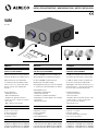
VAM
Ves 250
ACOUSTIC FAN
(FOR UP TO 6 WET ROOMS)
VAM is a silent fan to be directly installed
inside the dwelling, in the inhabited space.
VAM is optimised to be installed with
local demand controls (humdity sensitive,
motion sensor, etc.), up to 6 units, which
allows to get a B class regarding ErP
Directive.
Field of application:
· Dwellings and oces.
· New and refurbishment.
· Installation in cupboards, loft places,
bathrooms, toilets, corridors or any other
inner rooms.
· Wall, ceiling or on the ground.
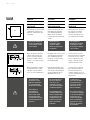
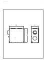
CONTENTS
A. Case + access door
B. Motor and propeller
C. Power supply wire
D. Fixing accessories
ACCESSORIES (NOT SUPPLIED)
E. Adaptor for Ø80mm duct (ref. AEA810)
F. Adaptor for Ø100mm duct (ref. AEA809)
G. Adaptor for Ø125mm duct (ref. AEA808)
SCHALLGEDÄMMTER VENTILATOR
(FÜR BIS ZU 6 FEUCHTRÄUME)
Der VES250 (VAM) ist ein leiser Ventilator, der
direkt im Wohnbereich installiert werden kann
Der VES 250 (VAM) ist optimiert um mit
Abluftelemente mit variabler (Hygro,
Bewegungsmelder usw.), bis zu 6, die ermöglicht
es, eine B-Klasse über ErP-Richtlinie zu erhalten.
Anwendungsbereiche:
· Wohnräume und Büroräume.
· Neubau und Sanierung.
· Installation in Schränken, Dachböden,
Badezimmern, Toiletten, Gängen oder sonstigen
Innenräumen.
· Wand, Decke, Boden.
CONTENTS
A. Gehäuse + Deckel
B. Motor und Turbine
C. Stromkabel
D. Befestigungszubehör
ZUBEHÖR (NICHT INBEGRIFFEN)
E. Anschlussmanschette Ø80mm (VESA 250/80)
F. Anschlussmanschette Ø100mm (VESA 250/100)
G.Anschlussmanschette Ø125mm (VESA 250/125)
VENTILATEUR ACOUSTIQUE
(JUSQU’À 6 PIÈCES HUMIDES)
Le VAM est un ventilateur silencieux pouvant
être installé directement dans l’espace habité.
Le VAM est optimisé lorsqu’il est installé avec
des bouches d’extraction à débit variable
(hygroréglable, détection de mouvement, etc.),
jusqu’à 6 bouches, ce qui lui permet d’obtenir
une classe B au sens de la directive ErP.
Domaines d’application :
· Logements et bureaux.
· Neuf et rénovation.
· Installation dans les placards, greniers, salles
de bain, toilettes, couloirs ou toute autre
pièce à l’intérieur du logement.
· Mur, plafond ou sol.
CONTENU
A. Caisson + couvercle
B. Moteur et turbine
C. Cordon d’alimentation électrique
D. Accessoires de fixation
ACCESSOIRES (NON FOURNIS)
E. Adaptateur conduit Ø80mm (ref. AEA810)
F. Adaptateur conduit Ø100mm (ref. AEA809)
G. Adaptateur conduit Ø125mm (ref. AEA808)
C
A
B
D E F G

2 AERECO – D4266_F
ENGLISH FRANÇAISDEUTSCH
WARNINGS
·Installation of this product must be
carried out by a qualified technician.
·Manufacturer and distributors decline
responsibility in the event of non
conformed use of the product.
·If the product is used in a way not
specified in this document, the
protection of the product can be
compromised.
·This appliance is not intended for use
by persons (including children over
8 years old) with reduced physical,
sensory or mental capabilities, or lack
of experience and knowledge, unless
they have been given supervision
or instruction concerning use of the
appliance by a person responsible for
their safety. To avoid any risk, do not
allow them to play with the appliance.
·Cleaning and maintenance by the user
should not be done by unattended
children.
TECHNICAL DETAILS
Specific Energy Consumption* : -26.2 kWh/(m².a)
Classification* : B
Maximum airflow: 250m3/h
Maximum pressure: 130 Pa
Sound level Lp @ 100m3/h: 29 dB(A)
Power @ 200m3/h: 44W
Supply: 230VAC +/- 10%
Frequency: 50Hz or 60Hz
Use: indoor
Storage temperature: from -20°C to + 55 °C
Working temperature: from +5°C to +40°C.
Pollution degree: 2
Manufactured in France by Aereco SA
ACHTUNG
·Die Montage dieses Ventilators darf
nur von einer Fachfirma durchgeführt
werden.
·Hersteller und Vertreiber haften nicht
bei nicht gerätekonformer Nutzung des
Produkts.
·Der Geräteschutz kann beeinträchtigt
werden, wenn das Produkt nicht
anleitungsgemäß verwendet wird.
·Das Gerät darf NICHT von Kindern
(mindestens 8 Jahre alt) oder
Personen mit reduzierten physischen,
sensoriellen oder geistigen Fähigkeiten
benutzt werden oder von solchen,
deren Erfahrung und Kenntnisse hierfür
nicht ausreichend sind, es sei denn, sie
haben die diesbezüglich erforderlichen
Anweisungen von einer, für ihre
Sicherheit verantwortlichen Person
erhalten.
·Montage, elektrischer Anschluss,
Inbetriebnahme und Wartung
des Gerätes, darf nur durch eine
entsprechend ausgebildete Fachkraft
erfolgen.
TECHNISCHE DATEN
Spezifischer Energieverbrauch* : -26.2 kWh/(m².a)
Klassifikation* : B
Höchstleistung: 250m3/h
Druckdierenz: 130 Pa
Lärmpegel Lp @ 100m3/h: 29 dB(A)
Leistung @ 200m3/h: 44W
Versorgung: 230VAC +/- 10%
Frequenz: 50Hz oder 60Hz
Anwendung: indoor
Lagertemperatur: von -20°C bis + 55°C
Betriebstemperatur: von +5°C bis +40°C.
Verschmutzungsgrad: 2
Hergestellt in Frankreich von Aereco SA
ATTENTION
·L’installation de ce produit doit être
eectuée par un technicien qualifié.
·Fabricants et distributeurs declinent
toute responsabilité en cas d’utilisation
non conforme du produit.
·La protection de ce produit peut être
compromise si le produit est utilisé
d’une autre manière que celle spécifiée
dans cette notice.
·Cet appareil peut être utilisé par des
enfants âgés d’au moins 8 ans et par
des personnes ayant des capacités
physiques, sensorielles ou mentales
réduites ou dénuées d’expérience ou
de connaissance, s’ils (si elles) sont
correctement surveillé(e)s ou si des
instructions relatives à l’utilisation de
l’appareil en toute sécurité leur ont
été données et si les risques encourus
ont été appréhendés. Les enfants ne
doivent pas jouer avec l’appareil.
·Le nettoyage et l’entretien par l’usager
ne doivent pas être eectués par des
enfants sans surveillance.
DÉTAILS TECHNIQUES
Consommation d’énergie spécifique* : -26.2 kWh/(m².an)
Classification* : B
Débit maximum : 250m3/h
Pression maximale: 130 Pa
Niveau sonore Lp @ 100m3/h : 29 dB(A)
Puissance @ 200m3/h : 44W
Alimentation : 230VAC +/- 10%
Fréquence : 50Hz or 60Hz
Utilisation : intérieur
Température de stockage : de -20°C to + 55 °C
Temp. de fonctionnement : de +5°C to +40°C.
Degré de pollution : 2
Fabriqué en France par Aereco SA
* : Dans le cadre de la directive Européenne 2009/125/
CE, les valeurs indiquant la consommation d’énergie
spécifique et la classification ne sont garanties que dans
le cas où l’unité de ventilation soit de type centralisée
et installée avec au moins deux bouches d’extraction à
débit modulé.
* : Im Rahmen der Europäischen Richtlinie
2009/125/EG werden die Werte für den spezifischen
Energieverbrauch und die klassifikation nur
gewährleistet, wenn eine zentrale Lüftungsanlage mit
mindestens zwei feuchtegeführten Abluftelementen
installiert ist.
* : Following the implementation of the European Directive
2009/125 / EC, the values indicating the specific energy
consumption and the classification are guaranteed only if
the ventilation unit is installed as a ducted type and with
at least two local demand control units.

AERECO – D4266_F 3
ENGLISH DEUTSCH FRANÇAIS
ELECTRICAL SAFETY
VAM fan is 230VAC supplied. It is thus essential
to cut o the supply at the fuse board (0,5A
fuse required) before removing the access
panel (screwdriver required). VAM fan must be
directly connected to the fuse board (no other
apparels connected to the line).
·It is compulsory to cut o the supply of the
VAM before removing the access panel.
·Cut o can be realised at the fuse board
(0,5A fuse required) or by the mean of a
switch if installed next to the fan.
·As the power supply connector is a Y shape
type, it can be replaced exclusively by the
Manufacturer or by the After Sales Service.
·In order to avoid a hazard due to inadvertent
resetting of the thermal cutout, this
appliance must not be powered through an
external switching device such as a timer,
or connected to a circuit that is regularly
switched on and o by the power provider.
·
THERMOSWITCH WITH MANUAL
RESTARTING
In conformity to standard IEC 60335-2-80 VAM
fan is equipped with a thermoswitch which
cuts o automatically the supply as soon as
the internal temperature of the motor exceeds
150°C (over heating of the motor or too high
temperature of the exhausted air). Once the
default has been detected and corrected, wait 10
mn then start the fan by pushing on the circuit
breaker (or fuse) on the fuse board.
ELEKTRISCHE SICHERHEIT
Der VES250 wird mit 230 V versorgt. Daher
muss die Stromversorgung an der Schalttafel
unterbrochen werden (Sicherung 0,5A), bevor
der Deckel abgenommen wird (Schraubendreher
erforderlich). Der VES250 muss direkt an
die Schalttafel angeschlossen werden (es
darf kein anderes Gerät an dieselbe Leitung
angeschlossen werden).
·Bevor man das Ventilatorgehäuse abnimmt,
muss die Stromversorgung unterbrochen
werden!
·Der Strom kann direkt an der Schalttafel (0,5
A Sicherung) oder mit dem Trennschalter
neben dem Ventilator unterbrochen werden.
·Um eine Gefahr zu vermeiden, das
Stromkabel ist ein Y-Kabel und kann daher
nur vom Hersteller oder dem Kundendienst
ausgetauscht werde
·Um Gefahren durch ein versehentliches
Zurücksetzen des Temperaturbegrenzers
zu vermeiden, darf dieses Gerät nicht
durch ein externes Schaltgerät, wie eine
Zeitschaltuhr, mit Strom versorgt oder an
einen Stromkreis angeschlossen werden,
der vom Stromanbieter regelmäßig an- und
abgeschaltet wird.
THERMOSWITCH MIT MANUELLEM
NEUSTART
Gemäß Norm CEI 60335-2-80 ist der VAM
mit einem Thermoswitch ausgestattet, der
die Stromversorgung automatisch unterbricht,
wenn die geräteinterne Temperatur 150°C
übersteigt (Überhitzung des Motors bzw. zu
hohe Ablufttemperatur). Wenn der Fehler
erfasst und beigelegt ist, muss man 10 Minuten
warten, bevor man den Ventilator neu startet
(Schutzschalter oder Sicherung an der Schalttafel
betätigen).
SÉCURITÉ ÉLECTRIQUE
Le VAM est doté d’une alimentation 230V. Il
est donc essentiel de couper l’alimentation au
tableau électrique (fusible de 0,5A requis) avant
de retirer le couvercle (tournevis requis). Le VAM
doit être directement connecté au tableau
électrique (aucun autre appareil doit être
connecté sur la même ligne).
·Il est indispensable de couper l’alimentation
du VAM avant de retirer le couvercle.
·La coupure de courant peut se faire au
tableau électrique (fusible de 0,5A requis)
ou bien au moyen de l’interrupteur installé à
côté du ventilateur.
·Afin d’éviter un danger, comme le cordon
d’alimentation est de type Y, celui-ci ne peut
être remplacé que par le fabricant ou le SAV.
·Afin d’éviter un danger dû au réarmement
intempestif du coupe-circuit thermique,
cet appareil ne doit pas être alimenté par
l’intermédiaire d’un interrupteur externe,
comme une minuterie, ou être connecté à
un circuit qui est régulièrement mis sous
tension et hors tension par le fournisseur
d’électricité.
THERMOSWITCH À RÉENCLENCHEMENT
MANUEL
En application de la norme CEI 60335-2-80, le
VAM est équipé d’un thermoswitch qui coupe
automatiquement l’alimentation dès que la
température interne excède 150°C (surchaue
du moteur ou température trop élevée de l’air
expulsé). Une fois que le défaut a été détecté
et corrigé, attendre 10 min puis redémarrer le
ventilateur en enclenchant le disjoncteur (ou le
fusible) du tableau électrique.

4 AERECO – D4266_FAERECO – D4266_F 4
ENGLISH DEUTSCH FRANÇAIS
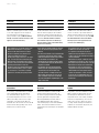
RECOMMANDATIONS FOR ACOUSTIC
PERFORMANCE
Even if the VAM fan has been optimised
regarding acoustics, some light noise may
appear in case of bad installation.
Very simple actions described as follows
enable to improve the acoustic performance
of the working fan, by limiting the
transmission of vibrations:
A - Use acoustic ducts or acoustic stoppers
for the parts which are directly in contact
with the fan, especially for the “inlet” ducts.
B - Ground installation: place an acoustic
insulant (foam, polystyren, etc) between the
fan and the ground.
C - Wall or ceiling installation: place a
silent block between each bracket and the
surface where the fan is installed.
RECOMMANDATIONS FOR AERAULIC
PERFORMANCE
Ductwork design:
· Before starting the installation, pay
attention of optimising the ductwork
by minimising the lengths and the
number of elbows, and by using
adequate diameters for ducts (Ø125mm
recommanded).
· Fan outlet must be at minimum Ø125mm.
· Fan discharge grille (in the roof or through
the wall) should not exceed 10 Pa pressure
drop at 250m3/h.
· No more than 2 air extract units per duct
connected to the fan.
EMPFEHLUNGEN FÜR DIE LEISTUNG DER
SCHALLDÄMMUNG
Der VES250 ist mit einer optimalen
Schalldämmung ausgestattet. Allerdings
kann es bei mangelhafter Installation zu
leichter Geräuschentwicklung kommen.
Die Schalldämmung des Ventilators
kann auch in Betrieb verbessert werden,
indem man die Schwingungsübertragung
folgendermaßen reduziert:
A - Der Einsatz von
Telefonieschalldämpfer und akustischem
Rohr ist empfohlen.
B - Bodeninstallation: Zwischen Ventilator
und Boden eine schalldämmende Schicht
anbringen (Schaum, Polystyren usw.).
C - Wand- oder Deckeninstallation:
Zwischen jeder Befestigung und der Wand
oder Decke einen Schalldämmmatte /
Vibrationsdämpfungsmatte installieren.
EMPFEHLUNGEN FÜR DIE
LUFTLEISTUNG
Leitungsnetz:
· Vor der Installation muss das Leitungsnetz
optimiert werden: Anzahl und Länge
der Winkel reduzieren und passende
Durchmesser verwenden (empfohlen
Ø125mm).
· Der Ventilatorausgang muss mind.
Ø125mm groß sein.
· Der Druckverlust am Ventilator-Abluftgitter
(Dach- oder Wanddurchführung) darf nicht
mehr als 10 Pa bei 250m3/h betragen.
· Nicht mehr als 2 Abluftelemente pro
angeschlossene Leitung.
RECOMMANDATIONS POUR LA
PERFORMANCE ACOUSTIQUE
Bien que le VAM ait été optimisé sur le plan
acoustique, il peut parfois émettre de légers
bruits en cas de mauvaise installation.
Les actions très simples décrites ci-dessous
permettent d’améliorer les performances
acoustiques du ventilateur en fonctionnement,
en limitant la transmission des vibrations :
A - Utiliser des conduits acoustiques ou
des pièges à son les parties de conduits
directement en contact avec le ventilateur,
spécialement au niveau des amenées d’air.
B - Installation au sol : Placer un isolant
acoustique (mousse, polystyrène, etc.) entre
le ventilateur et le sol.
C - Installation au mur ou au plafond :
Placer un silent block entre chaque fixation
et le mur sur lequel il est installé.
RECOMMANDATIONS POUR LA
PERFORMANCE AÉRAULIQUE
Réseau de conduits :
· Avant de démarrer l’installation, optimiser
le réseau de conduits en minimisant la
longueur et le nombre de coudes, et
en utilisant des diamètres adaptés
(Ø125mm recommandé).
· La sortie du ventilateur doit être
supérieure ou égale à Ø125mm.
· La grille de sortie du ventilateur (en toiture
ou murale) ne doit pas créer une perte de
charge excédant 10 Pa à 250m3/h.
· Pas plus de 2 bouches d’extraction par
conduit raccordées au ventilateur.
B
C
TOP
≥ 5mm
≥ 18 dB/m
≥ 5mm
≥ 18 dB/m

AERECO – D4266_F 5
ENGLISH FRANÇAISDEUTSCHVAM
Connect the adaptors to
the fan case preferably
in the positions marked
on the scheme.
Die Anschlussm-
anschetten sollten
möglichst gemäß
Zeichnung angeschlos-
sen werden.
Les adaptateurs
doivent être raccordés
de préférence selon
les positions indiquées
sur le schéma.
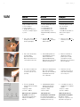
RECOMMANDATIONS FOR
FAN POSITION
First determine fan position and
configuration relatively to the
walls, the ceiling and the duct
connections.
EMPFEHLUNGEN FÜR DIE
VENTILATORPOSITION
Zuerst muss die Position und
Ausrichtung des Ventilators
unter Berücksichtigung der
Wände, der Decke und der
Leitungsanschlüsse festgelegt
werden.
POSITIONNEMENT DU
VENTILATEUR
Avant toute chose, déterminer
la position et l’orientation
du ventilateur en fonction
des murs, du plafond et des
raccordements aux conduits.
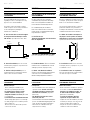
Make sure that the wall or the
ceiling to which the fan will
be fixed, is strong enough to
support the weight of the fan.
(18kg i.e. more than 4.5kg at
each fixing).
Die Wände oder Decken, an der
der Ventilator befestigt wird,
muss tragfähig genug sein.
(18kg d.h. 4,5kg an jedem
Befestigungspunkt).
S’assurer que le mur ou le
plafond sur lequel le ventilateur
va être fixé est assez solide
pour en supporter le poids.
(18kg i.e. plus de 4,5kg à
chaque point d’accroche).
TOP
4,5 kg ! 4,5 kg !
4,5 kg ! 4,5 kg !
18 kg !
Make sure that there is enough
room around the fan to enable
easy duct connection and free
access to cover for maintenance.
Rund um den Ventilator muss
genug Platz für den Anschluss
der Leitungen und den Zugri
auf den Ventilatordeckel zu
Wartungszwecken sein.
S’assurer qu’il y a assez de
place autour du ventilateur
pour relier facilement les
conduits et libérer l’accès au
couvercle du ventilateur pour la
maintenance.
The high acoustic
performance of the
VAM fan is optimised
by a good ductwork
design and installation.
Short elbows or
bad airtightness
may generate air
noises which would
considerably reduce
the overall acoustic and
aeraulics performance
of the fan.
Die Schalldämmungs-
werte des VES250
sind auf ein gut
angelegtes Leitungs-
netz und eine korrekte
Installation optimiert.
Zu enge Winkel oder
schlechte Abdichtung
können Luftgeräusche
verursachen und die
Schalldämmung und
Luftleistung des Ven-
tilators stark beein-
trächtigen.
La performance
acoustique du VAM
est optimisée par un
réseau de conduits
bien conçu et une
bonne installation.
Les coudes serrés ou
la mauvaise étanchéité
à l’air peuvent générer
des bruits d’air et
réduire considérable-
ment l’ensemble des
performances acous-
tiques et aérauliques
du ventilateur.

6 AERECO – D4266_F
ENGLISH FRANÇAISDEUTSCHVAM ENGLISH FRANÇAISDEUTSCH
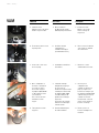
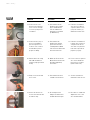
2. Take out the fan by using
the side handles.
(Check the exhaust
Ø125mm metal sleeve is
correctly fixed on the fan.)
2. Das Ventilatorgehäuse an
den Handgrien aus dem
Karton herausziehen.
(Die Metall-Abluftleitung
Ø125mm muss korrekt am
Ventilator befestigt sein).
2. Retirer le ventilateur en
utilisant les poignées.
(Vérifier que le conduit
d’évacuation en métal
Ø125mm est correctement
fixé au ventilateur).
1. Take out the motor b and
the bag of accessories d
from the packaging.
1. Den Motor b und das
Zubehör (Tüte) d aus dem
Karton nehmen.
1. Retirer le moteur b et le
sachet d’accessoires d du
carton.
TOOLS REQUIRED
· 1 flat screwdriver n°6 or a coin
· 1 PZ2 screwdriver
· 1 PH1 screwdriver
· 1 drill Ø6mm for plaster or
concrete according to support
· 1 pencil
ERFORDERLICHES WERKZEUG
· 1 Schlitzschraubendreher Nr. 6
oder eine Münze
· 1 Schraubendreher PZ2
· 1 Schraubendreher PH1
· 1 Bohrer Ø6mm (je nach
Trägermaterial Gips oder Beton)
· 1 Stift
OUTILS NÉCESSAIRES
· 1 tournevis plat n°6 ou une
pièce de monnaie
· 1 tournevis PZ2
· 1 tournevis PH1
· 1 foret Ø6mm pour plâtre ou
béton selon le support
· 1 crayon
b
d
3. Use a flat screw driver n°6
or a coin to unscrew the
4 screws of the fan cover
(1/4 turn).
3. Mit einem Schraubendreher
Nr. 6 oder einer Münze
drehen Sie die 4 Schrauben
des Gehäusedeckels um
eine ¼ Drehung.
3. Dévisser les 4 vis du
couvercle (1/4 de tour) à
l’aide d’un tournevis plat
n°6 ou une pièce.
4. The fan is standardly
delivered with the following
settings:
· frequency = 50Hz
· pressure = 100 Pa
100 Pa pressure is generally
acceptable. Nevertheless,
other frequency and pressure
settings are available (see
page11).
4. Standardgemäß wird der
Ventilator mit folgenden
Einstellungen geliefert:
· Frequenz = 50Hz
· Druck = 120 Pa
120 Pa Druck sind
normalerweise ausreichend.
Es stehen aber auch andere
Frequenzen und Druckwerte zur
Verfügung (siehe Seite 11).
4. Le ventilateur est livré en
standard avec les réglages
suivants :
· fréquence = 50Hz
· pression = 100 Pa
100 Pa de pression est
générallement acceptable.
Néanmoins, d’autres
fréquences et pressions sont
disponibles (voir page11).

AERECO – D4266_F 7
ENGLISH FRANÇAISDEUTSCHVAM
7. Connect the connector to
the motor plug.
7. Stromkabel an den Motor
anschließen.
7. Brancher le cordon
d’alimentation au moteur.
6. Fix the motor with 4 screws
by using a PZ2.
6. Den Motor mit den
4 mitgelieferten
Schrauben befestigen
(Schraubendreher PZ2).
6. Fixer le moteur à l’aide des
4 vis fournies en utilisant
un tournevis PZ2.
8. Once configuration of
the ducts is determined
(see page5), replace
the acoustic stoppers
by adaptors (Ø80, Ø100
or Ø125mm) for all the
selected ducts:
First, remove the foam
behind the acoustic
stopper.
8. Sobald die Leitungs-
konfiguration festgelegt
ist (siehe Seite 5),
werden die entsprechenden
Schallstopfen entfernt und
die Adapter (Ø80, Ø100
oder Ø125mm) für die
gewünschten Leitungen
eingesetzt:
Zuerst muss der Schaum
hinter dem Schallstopfen
entfernt werden.
8. Une fois que la
configuration des
conduits est définie (voir
page5), remplacer les
bouchons acoustiques par
les adaptateurs (Ø80, Ø100
or Ø125mm) pour tous les
conduits sélectionnés :
Premièrement, enlever la
mousse située derrière le
bouchon acoustique.
9. Then push the acoustic
stopper in.
9. Dann den Metallstopfen
nach Innen drücken.
9. Ensuite, pousser le
bouchon métallique vers
l’intérieur.
5. Install the motor:
Align the notch of the motor
and the suspension wire.
5. Motor installieren:
Die Motorkerbe und die
Aufhängestange ausrichten.
5. Installer le moteur:
Aligner l’encoche du
moteur et la tige de
suspension.

8 AERECO – D4266_F
ENGLISH FRANÇAISDEUTSCHVAM
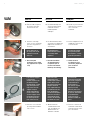
Please take care of
the sharp sides of the
adaptors! To handle
with care.
Die Adapterkanten
sind manchmal scharf
– vorsichtig damit
umgehen!
Les bords des adapta-
teurs peuvent parfois
être coupants – à mani-
puler avec précaution !
12. Check the good
installation of the rubber
ring (important for a good
seal).
12. Korrekte Installation
der Gummidichtung
nachprüfen (das ist
für eine einwandfreie
Dichtung sehr wichtig).
12. Vérifier la bonne
installation du joint
caoutchouc (important
pour une bonne
étanchéité).
11. Insert the connecting
sleeve. In case of problems,
put some soapy water on
the sleeve.
11. Die Anschlussmanschette
einschieben. Bei Bedarf den
Adapter mit Seifenwasser
einschmieren.
11. Insérer l’adaptateur. En cas
de diculté, y déposer de
l’eau savonneuse.
If an acoustic stopper
is removed by
mistake, replace it by
positioning foam in
the hole (leave a small
gap). Then place the
ring on the acoustic
stopper and push
gently and gradually
on the surface of the
acoustic stopper, until
the groove of the ring
fits the shape of the
hole of the fan case.
Wenn Sie irrtüm-
licherweise einen
Schallstopfen entfernt
haben, muss zuerst
der Schaum, dann der
Stopfen wieder im
Loch angebracht wer-
den (Abstand lassen).
Dann die Dichtung
auf den Schallstopfen
legen und vorsichtig
und langsam hinein-
drücken, bis der Stop-
fen wieder fest sitzt.
Si un bouchon
acoustique est enlevé
par erreur, le replacer
en positionnant la
mousse dans le
trou (laisser un petit
espace). Ensuite,
placer le joint sur le
bouchon acoustique et
le pousser doucement
et graduellement,
jusqu’à ce que le
bouchon soit bien en
place.
10. Take the rubber ring from
the stopper, then put it
back on the fan case.
10. Die Gummidichtung vom
Stopfen herunternehmen
und wieder auf dem
Ventilatorgehäuse
anbringen.
10. Prendre le joint caoutchouc
du bouchon et le replacer
sur le caisson du
ventilateur.
13. Close the cover of the fan
by using a flat screwdriver
n°6 or a coin.
13. Mit einem flachen
Schraubendreher Nr. 6
oder einer Münze den
Gehäusedeckel des
Ventilators schließen.
13. Fermer le couvercle du
ventilateur en utilisant un
tournevis plat n°6 ou une
pièce de monnaie.

AERECO – D4266_F 9
ENGLISH FRANÇAISDEUTSCHVAM
15. Position the fan (case) on
the chosen installation
place then plot the four
locations of the screws in
the wall with a pencil to
prepare for drilling.
15. Den Ventilator am
gewünschten Standort
positionieren und die 4
Schraubpunkte an Wand
oder Decke zum Bohren mit
dem Stift vorzeichnen.
15. Positionner le ventilateur à
l’endroit choisi et tracer les
4 emplacements des vis
sur le mur ou le plafond à
l’aide d’un crayon afin de
préparer le perçage.
14. Position the fan on its
back to fix the 4 brackets
on the corners each with
2 screws, by using a PZ2
screwdriver.
14. Den Ventilator auf die
Rückseite legen und mit
dem Schraubendreher
PZ2 die 4 Winkeleisen
befestigen (2 Schrauben
pro Winkeleisen).
14. Positionner le ventilateur
sur le dos pour y fixer les
4 équerres dans les coins
(2 vis pour chacune), en
utilisant un tournevis PZ2.
16. Drill the wall or the ceiling
with a Ø6mm drill then
insert the plugs (provided in
the kit).
16. Wand oder Decke mit der
Ø6mm Bohrer bohren und
die Dübel (mitgeliefert)
einschieben.
16. Percer le mur ou le plafond
avec un foret de Ø6mm
puis insérer les chevilles
(fournies dans le kit).
17. Firmly secure the fan with
the 4 screws.
17. Den Ventilator mit den 4
Schrauben sicher fixieren.
17. Sécuriser fermement le
ventilateur à l’aide de 4 vis.
18. Connect the ducts to the
sleeves and seal them with
an adhesive tape.
18. Die Leitungen an die
Adapter anschließen und
mit Klebeband versiegeln.
18. Raccorder les conduits aux
adaptateurs et les sceller
avec du ruban adhésif.

10 AERECO – D4266_F
ENGLISH FRANÇAISDEUTSCH
ELECTRICAL CONNECTION
Use a 0.5A fuse on the electric board,
and cut o before making any electrical
connection.
Connect the fan wires to the electric supply
according to the scheme above. Make
sure that the jumper (50 or 60Hz, see
page11) corresponds to the frequency
available.
ELEKTRISCHER ANSCHLUSS
Für die Schalttafel eine 0,5 A Sicherung
verwenden. Vor elektrischen Anschlüssen
den Strom unterbrechen.
Die Ventilatordrähte an die Stromversorgung
anschließen. Der Reiter (50 oder 60Hz,
siehe Seite 11) muss der verfügbaren
Frequenz entsprechen.
BRANCHEMENTS ÉLECTRIQUES
Utiliser un fusible de 0,5A au tableau
électrique et couper le courant avant de
réaliser tout branchement électrique.
Brancher les fils du ventilateur à
l’alimentation. S’assurer que le cavalier
(50 ou 60Hz, voir page11) correspond
à la fréquence disponible.
PRESSURE / FREQUENCY SETTING
VAM fan oers the possibility to set the
working pressure. The supply frequency can
also be adapted to 60Hz.
3 pressures are available :
· 80 Pa
· 100 Pa
· 120 Pa
VAM fan is standardly delivered at 100 Pa,
50Hz.
DRUCKEINSTELLUNG / FREQUENZ
Beim VAM lässt sich der Betriebsdruck
einstellen. Die Netzfrequenz kann auch an
60Hz angepasst werden.
3 Druckeinstellungen sind möglich:
· 80 Pa
· 100 Pa
· 120 Pa
Standardgemäß wird der VAM mit 120 Pa,
50Hz geliefert.
RÉGLAGES PRESSION / FRÉQUENCE
Le VAM ore la possibilité de régler la
pression de fonctionnement. La fréquence
d’alimentation peut aussi être adaptée à
60Hz.
3 pressions sont disponibles :
· 80 Pa
· 100 Pa
· 120 Pa
Le VAM est livré en standard à 100 Pa, 50Hz.
brown = line braun marron
yellow-green =
ground
gelb-grün jaune-vert

AERECO – D4266_F 11
ENGLISH
FRANÇAIS
DEUTSCH
Anhand folgender Tabelle kann der Installateur den passenden wDruck für das jeweilige Leitungsnetz einstellen. Von der Auswahl des Drucks
hängt nicht nur die Gesamtleistung, sondern auch der Stromverbrauch und der Lärmpegel ab.
Leitungsnetz Kurz Normal Lang
Rohrleitungsnetz Kurze Rohrleitung, wenige oder keine
Winkel Längere Rohrleitung, wenige Winkel Lange Rohrleitung, viele Winkel
Position des Schalters 123
Laufdruck 80 Pa 100 Pa 120 Pa
Einfluss auf Stromverbrauch
und der Lärmpegel
Geringer Stromverbrauch
Geringe Geräuschentwicklung
Mehr Stromverbrauch
Höhere Geräuschentwicklung
Le tableau ci-dessous permet à l’installateur de régler la bonne pression selon la configuration du réseau de conduits. Le choix de la pression
déterminera non seulement le débit total mais aussi la consommation électrique et le niveau sonore émis.
Type de réseau Court Normal Long
Caractéristiques Faibles longueurs, très peu de coudes Longueurs standards, coudes en quantité
raisonnable
Grandes longueurs, avec beaucoup de
coudes
Position de l’interrupteur 123
Pression choisie 80 Pa 100 Pa 120 Pa
Consommation électrique et
performance acoustique
Consommation faible
Bruit peu élevé
Consommation élevée
Bruit élevé
The table below can help the installer to set the right pressure according to the ductwork configuration. The pressure choice will determine not
only the total airflow but also the power consumption and the proper noise emitted.
Type of the ductwork Short Normal Long
Characteristics Small lenghts, very few elbows Standard lenghts, elbows in reasonable
quantity Long lenghts, with a lot of elbows
Position of the jumper 123
Chosen pressure 80 Pa 100 Pa 120 Pa
Electrical consumption and
acoustic performance
Less consumption
Less noise
More consumption
More noise

12 AERECO – D4266_F
ENGLISH FRANÇAISDEUTSCH
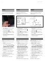
The pressure (and the frequency) can be
changed at the electric box as described
below:
1. Unscrew the electric box lid by using a
PH1 screwdriver.
2. If the frequency available is 60Hz,
remove the jumper a.
3. Position the jumper b on the position
(pressure) chosen (1 = 80 Pa, 2 = 100
Pa, 3 = 120 Pa)
4. Remount and screw the electric box lid,
then put back in place the motor set
inside the fan.
MAINTENANCE
Every year and preferably before the heating
season :
1. Remove the fuse of the fan on the fuse
board.
2. Remove the cover of the fan
(4x¼screws), use a flat screwdriver
n°6 or a coin. Be careful with a ceiling
assembly: the cover is not secured
while the 4 screws are unscrewed.
3. Disconnect the electric plug of the motor.
4. Remove the motor by using a PZ2
screwdriver.
5. Use a brush to clean the blades of the
motor (never use water or chemical
products).
6. Clean the casing with a dry wipe.
7. Reinstall the motor in the same position.
8. Reconnect the motor.
9. Close the cover.
10. Reposition the fuse on the board.
Druck (und Frequenz) können am
Schaltkasten geändert werden. Dazu wie
folgt vorgehen:
1. Schaltkasten mit dem Schraubendreher
PH1 aufschrauben.
2. Verfügbare Frequenz 60Hz: Reiter a
verschieben.
3. Den Reiter b auf die gewünschte
Position (Druck) stellen. (1 = 80 Pa, 2 =
100 Pa 3 = 120 Pa)
4. Den Deckel des Schaltkastens wieder
anbringen und festschrauben. Den Motor-
block wieder in den Ventilator einbauen.
WARTUNG
Jährliche Wartung möglichst vor der kalten
Jahreszeit:
1. Ventilatorsicherung aus der Schalttafel
nehmen.
2. Ventilatordeckel abnehmen (4x¼Dre-
hungen), mit einem flachen Schrau-
bendreher Nr. 6 oder einer Münze.
Vorsicht bei Deckenmontage: Die
Abdeckung ist nicht mehr gesichert,
wenn die 4 Schrauben gelöst sind!
3. Motor-Stromstecker abnehmen.
4. Die Turbinen-Motorgruppe mit dem
Schraubendreher PZ2 entfernen.
5. Mit einer Bürste die Turbinenlamellen
reinigen (niemals mit Wasser oder
Chemikalien reinigen!).
6. Den Ventilator Innen mit einem trocke-
nen Lappen reinigen.
7. Die Turbinen-Motorgruppe wieder einbauen.
8. Den Motor anschließen.
9. Den Deckel schließen.
10. Sicherung wieder in der Schalttafel einlegen.
La pression (et la fréquence) peuvent être
changées au boîtier électrique, comme
décrit ci-dessous :
1. Dévisser le boîtier électrique avec un
tournevis PH1.
2. Si la fréquence disponible est de 60Hz,
retirer le cavalier a.
3. Placer le cavalier b sur la position
(pression) choisie (1 = 80 Pa, 2 = 100
Pa, 3 = 120 Pa)
4. Remonter et visser le couvercle du boîtier
électrique et replacer le bloc moteur à
l’intérieur du ventilateur.
ENTRETIEN
Chaque année et de préférence avant la
saison de chauage :
1. Enlever le fusible du ventilateur sur le
tableau électrique.
2. Enlever le couvercle du ventilateur
(4x¼tours), avec un tournevis plat n°6
ou une pièce. Faire attention lorsqu’il est
monté au plafond : le capot n’est pas
sécurisé quand les 4 vis sont dévissées.
3. Débrancher la prise d’alim. du moteur.
4. Retirer l’ensemble turbine-moteur à
l’aide d’ un tournevis PZ2.
5. Utiliser une brosse pour nettoyer les
lames de la turbine (ne jamais utiliser
d’eau ou de produit chimique).
6. Nettoyer l’intérieur du ventilateur à l’aide
d’un chion sec.
7. Réinstaller l’ensemble turbine-moteur
dans la même position.
8. Rebrancher le moteur.
9. Fermer le couvercle.
10. Remettre le fusible au tableau.
a
b
80 Pa 100 Pa 120 Pa

AERECO – D4266_F 13
480
241480

14 AERECO – D4266_F
Notes:

AERECO – D4266_F 15
Notes:

D4266_F
Aereco S.A.
62 rue de Lamirault
Collégien
77615 MARNE LA VALLEE CEDEX 3
FRANCE
www.aereco.com
-
 1
1
-
 2
2
-
 3
3
-
 4
4
-
 5
5
-
 6
6
-
 7
7
-
 8
8
-
 9
9
-
 10
10
-
 11
11
-
 12
12
-
 13
13
-
 14
14
-
 15
15
-
 16
16


dans d''autres langues
- English: Aereco VAM Installation guide
- Deutsch: Aereco VAM Installationsanleitung
Documents connexes
-
Aereco V2A Installation Instructions Manual
-
-
-
-
-
-
-
-
-
