
IM 701921-01E 1/2
Use
r’s
Manual
Thank you for purchasing the Differential Probe (Model 701921) for the DL Series. To ensure correct
use, please read this manual thoroughly before beginning operation. After reading the manual, keep it
in a convenient location for quick reference whenever a question arises during operation.
Contact information of Yokogawa offices worldwide is provided on the following sheet.
• PIM113-01Z2 Listofworldwidecontacts
Model 701921
Differential Probe
for the DL Series
8th Edition: May 2018 (YMI)
AllRightsReserved,Copyright©2003,YokogawaElectricCorporation
All Rights Reserved, Copyright © 2010, Yokogawa Test & Measurement Corporation
Printed in Japan
The Following Symbols are Used in this Manual.
Improper handling or use can lead to injury to the user or damage to the instrument.
This symbol appears on the instrument to indicate that the user must refer to the
user’s manual for special instructions. The same symbol appears in the corresponding
place in the user’s manual to identify those instructions. In the manual, the symbol is
used in conjunction with the word “WARNING” or “CAUTION.”
WARNING
Calls attention to actions or conditions that could cause serious or fatal injury to the
user, and precautions that can be taken to prevent such occurrences.
CAUTION
Calls attentions to actions or conditions that could cause light injury to the user or
damage to the instrument or the user’s data, and precautions that can be taken to
prevent such occurrences.
French
AVERTISSEMENT
Attire l’attention sur des gestes ou des conditions susceptibles de provoquer
des blessures graves (voire mortelles), et sur les précautions de sécurité
pouvant prévenir de tels accidents.
ATTENTION
Attire l’attention sur des gestes ou des conditions susceptibles de provoquer des
blessures légères ou d’endommager l’instrument ou les données de l’utilisateur, et
sur les précautions de sécurité susceptibles de prévenir de tels accidents.
Note
Calls attention to information that is important for proper operation of the instrument.
Safety Precautions
This product is designed to be used by a person with specialized knowledge.
Make sure to comply with the safety precautions mentioned hereafter when handling the probe.
YOKOGAWA assumes no responsibility for any consequences resulting from failure to comply with
these safety precautions. Also, read the User’s Manual of the measuring instrument thoroughly so that
you are fully aware of its specifications and handling, before starting to use the probe.
This manual is part of the product and contains important information. Store this manualin a safe place
close to the instrument so that you can refer to it immediately. Keep this manual until you dispose of
the instrument.
The following symbols are used on this instrument.
Handle with care. Refer to the user’s manual or service manual. This symbol appears on
dangerous locations on the instrument which require special instructions for proper handling
or use. The same symbol appears in the corresponding place in the manual to identify those
instructions.
Risk of electric shock
French
À manipuler délicatement. Toujours se reporter aux manuels d’utilisation et d’entretien. Ce
symbole a été apposé aux endroits dangereux de l’instrument pour lesquels des consignes
spéciales d’utilisation ou de manipulation ont été émises. Le même symbole apparaît à l’endroit
correspondant du manuel pour identifier les consignes qui s’y rapportent.
Risque de choc électrique
Make sure to comply with the following safety precautions in order to prevent accidents
such as an electric shock which impose serious health risks to the user and damage to the
instrument.
WARNING
Grounding of the measuring instrument
The protective grounding terminal of the measuring instrument must be connected to ground.
Connecting the object of measurement
Make sure to avoid an electric shock when connecting the probe to the object of
measurement. Do not remove the probe from the measuring instrument after the object of
measurement is connected.
Do not operated with suspected failures
If you suspect that there is damage to this probe, have it inspect by a service personnel.
Observe maximum working voltage
To avoid any injury, do not use the probe above 1000 Vpeak between each input lead and
earth or between the two inputs.
This voltage rating applies to both 1/10 and 1/100 settings.
Must be grounded
This probe must be grounded with the BNC shell and an auxiliary grounding terminal,
through the grounding conductor of the power cord of the measuring instrument or other
appropriate grounding conductor. Before making connections to the input terminals of the
product, ensure that the output connector is attached to the BNC connector of the measuring
instrument and the auxiliary grounding terminal is connected to a proper ground, while the
measuring instrument is properly grounded.
Do not operate in wet/damp conditions
To avoid electric shock, do not operate this probe in wet or damp conditions.
Do not operate in explosive atmosphere
To aviod injury or fire hazard, do not operate this probe in an explosive atmosphere.
Avoid exposed circuitry
To avoid injury, remove jewelry such as rings, watches, and other metallic objects. Do not
touch exposed connections and components when power is present.
Do not disassemble or modify
Do not disassemble or modify the product. YOKOGAWA assumes no liability if you
disassemble or modify the product.
Damaged Signal Cable
If the signal cable is torn and the inner metal is exposed or if a color different from the outer
sheath appears, stop using the cable immediately.
CAUTION
Maximum input voltage
Do not apply any voltages exceeding the maximum input voltage to the probe.
Correct use of the power supply
Power the probe with either 4 AA dry cells, a 6 VDC/200 mA or 9 VDC/150 mA external
power supply, or by connecting the probe’s power cable to a probe power supply terminal on
aDLseriesmeasuringinstrumentortothe700938or701934.Operatingtheprobeundera
power supply greater than the voltage specified above may cause damage to the instrument.
Connecting the external power supply to the probe
Always turn OFF the probe’s power switch when connecting or disconnecting the external
power supply. Also, do not install the dry cells when using an external power supply.
Conditions of use
This product has not been designed or manufactured for applications in which high reliability
is required over a long time period.
Operating environment limitations
This product is a Class A (for industrial environments) product. Operation of this product in
a residential area may cause radio interference in which case the user will be required to
correct the interference.
French
AVERTISSEMENT
Mise à la terre de l’instrument de mesure
S’assurer de connecter la mise à la terre protectrice de l’instrument de mesure.
Connexion de l’objet de la mesure
S’assurer d’éviter un choc électrique lors de la connexion de la sonde à l’objet de la mesure.
Ne pas retirer la sonde de l’instrument de mesure après avoir connecté l’objet de la mesure.
Ne pas utiliser en cas de défaillances suspectées
Si vous suspectez que la sonde est endommagée, contactez votre revendeur ou
représentant commercial YOKOGAWA.
Respecter la tension d’entrée maximum
Ne pas appliquer une tension dépassant 1000 V (c.c. + crête c.a.) entre un fil d’entrée et la
terre ou entre deux fils d’entrée. La tension d’entrée maximum est de 1000 V (c.c. + crête c.a.)
sans tenir compte de l’atténuation utilisée, 10:1 ou 100:1.
Doit être mis à terre
Cette sonde doit être mise à terre avec le connecteur BNC et le connecteur de terre
auxiliaire du cordon d’alimentation de l’instrument de mesure ou d’un autre conducteur de
mise à la terre approprié. Avant d’effectuer les connexions aux bornes d’entrée du produit,
vérifiez que le connecteur de sortie est connecté au connecteur BNC de l’instrument de
mesure et que la borne de mise à la terre auxiliaire est connectée à une mise à la terre
appropriée.
Ne pas utiliser dans des conditions humides
Afin d’éviter un choc électrique, ne pas utiliser cette sonde dans des conditions humides.”
Ne pas utiliser dans une atmosphère explosive
Afin d’éviter des risques de blessures ou d’incendie, ne pas utiliser cette sonde dans une
atmosphère explosive.
Éviter les circuits exposés
Afin d’éviter des blessures, retirer les bijoux comme les bagues, montres et autres objets
métalliques. Ne pas toucher les connexions et les composants exposés après mise sous
tension.
Ne pas démonter ou modifier
Ne pas démonter ou modifier le produit. YOKOGAWA se dégage de toute responsabilité si
vous démontez ou modifiez le produit.
Câble de signal endommagé
Si le câble de signal est déchiré et que le métal intérieur est exposé ou si une couleur
différente de la gaine externe est visible, arrêter immédiatement d’utiliser ce câble.
ATTENTION
Tension d’entrée maximum
Ne pas appliquer à la sonde de tension dépassant la tension d’entrée maximum.
Utilisation adéquate de l’alimentation
Alimenter la sonde avec 4 piles sèches AA, avec une alimentation externe 6 VDC/200
mA ou 9 VDC/150 mA, ou en connectant le câble d’alimentation de la sonde à une borne
d’alimentationsuruninstrumentdemesuresérieDLouau700938ou701934.L’utilisation
de la sonde sous une alimentation supérieure à la tension spécifiée ci-dessus peut
endommager l’instrument.
Connexion de l’alimentation externe à la sonde
Toujours éteindre l’interrupteur d’alimentation de la sonde lors de la connexion ou de la
déconnexion de l’alimentation externe.En outre, n’installez pas les piles sèches lorsque vous
utilisez une alimentation externe.
Conditions d’utilisation
Ce produit n’est pas conçu ou fabriqué pour des applications nécessitant une fiabilité élevée
sur une longue période.
Limitations relatives à l’environnement opérationnel
Ce produit est un produit de classe A (pour environnements industriels). L’utilisation de ce
produit dans un zone résidentielle peut entraîner une interférence radio que l’utilisateur sera
tenu de rectifier.
Waste Electrical and Electronic Equipment
Waste Electrical and Electronic Equipment (WEEE), Directive
(This directive is valid only in the EU.)
This product complies with the WEEE directive marking requirement. This marking
indicates that you must not discard this electrical/electronic product in domestic
household waste.
Product Category
With reference to the equipment types in the WEEE directive, this product is classified
as a “Monitoring and control instruments” product.
When disposing products in the EU, contact your local Yokogawa Europe B.V. office.
Do not dispose in domestic household waste.
Authorized Representative in the EEA
Yokogawa Europe B.V. is the authorized representative of Yokogawa Test & Measurement Corporation
for this product in the EEA. To contact Yokogawa Europe B.V., see the separate list of worldwide
contacts,PIM113-01Z2.
IM 701921-01E
8th Edition

IM 701921-01E 2/2
1 Description
By using this device, oscilloscopes with single-ended input can be easily used as oscilloscopes with
differential inputs.
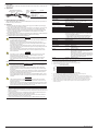
2 Appearance
25 cm
90 cm
ADJUST (DC offset adjustment)
Standard Parts Parts No
Attenuation switch
Power switch
* Power can be supplied from the YOKOGAWA
measuring instrument or 700938, 701934.
1 Probe
2 Pinchers tips
3 Ground extention lead
(length = 100 cm)
4 Power cable*
(length = 150 cm)
-
Black: B9852MM
Red: B9852MN
-
B9852MJ
1
2
3
4
Auxiliary
grounding
terminal
3 Installing/Replacing the Batteries
Shift the lid at the back side of the probe and install/replace the four dry cells. The dry cells are not
installed on receipt of the instrument.
4 Operation
1. Install four AA cells. When using an external power supply, do not install the dry cells. Supply
power only through the external power supply.
2. Simply plug-in the BNC output connector to the vertical input of a oscilloscope, and connect the
auxiliary grounding terminal to a proper ground. If necessary, use a ground extention lead.
3. Select the proper range setting. For higher resolution and less noise when measuring signals
below 70 V, switch the attenuation to 1/10. Otherwise, set the attenuation to 1/100 when
measuring signals above 70 V.
4. If the offset voltage is large, short the top of input leads, and turn the ADJUST variable resistor (DC
voltage adjustment) using a flat-head screwdriver to adjust the offset voltage.
5. Connect the input to the circuits under measurement.
WARNING
• Toprotectagainstelectricshockthegroundsideoftheoutputcable(theshieldedsideof
the BNC connector) must be grounded.
• Makesuretoavoidanelectricshockwhenconnectingtheprobetotheobjectof
measurement. Do not remove the probe from the measuring instrument after the object
of measurement is connected.
• WhendisconnectingtheprobeBNCoutputconnector,firstturnOFFthepowertothe
circuit under measurement. Then, disconnect the probe from the high voltage parts of the
circuit under measurement.
• Whenreplacingbatteriesorconnectinganexternalpowersupply,firstturnOFFthe
power to the circuit under measurement. Then, remove the input lead from the circuit
under measurement.
CAUTION
• Thisprobeistocarryoutdifferentialmeasurementbetweentwopointsonthecircuit
under measurement. This probe is not for electrically insulating the circuit under
measurement and the measuring instrument.
• Useasoftclothtocleanthedirt.Preventdamagetotheprobe.Avoidimmersingthe
probe, using abrasive cleaners, and using chemicals contains benzene or similar
solvents.
French
AVERTISSEMENT
• Pouréviterleschocsélectriques,lamiseàlaterreducâbledesortie(côtéblindédu
connecteur BNC) doit être effectuée.
• S’assurerd’éviterunchocélectriquelorsdelaconnexiondelasondeàl’objetdela
mesure. Ne pas retirer la sonde de l’instrument de mesure après avoir connecté l’objet
de la mesure.
• LorsdeladéconnexionduconnecteurdesortieBNCdelasonde,mettred’abordHORS
tension le circuit faisant l’objet de la mesure. Puis déconnecter la sonde des parties à
haute tension du circuit faisant l’objet de la mesure.
• Lorsduremplacementdespilesoudelaconnexiond’unealimentationexterne,coupez
d’abord l’alimentation du circuit sous tension. Ensuite, retirez le câble d’entrée du circuit
à mesurer.
ATTENTION
• Cettesondedoiteffectuerunemesuredifférentielleentredeuxpointssurlecircuità
mesurer.Cette sonde n’est pas destinée à isoler électriquement le circuit à mesurer et
l’instrument de mesure.
• Utiliserunchiffondouxpournettoyerlasonde.Faireattentiondenepascasserlasonde.
Ne pas immerger la sonde dans un liquide ni utiliser de nettoyants abrasifs sur la sonde.
Ne pas utiliser de benzène ni d’autres solvants sur la sonde.
Note
• ConnecttheBNCconnectortotheinputterminaloftheoscilloscopeandfortwopoint
measurement (differential measurement), connect both input leads. Because the performance
declines in case you carry out measurements with only one input lead connected, make sure to
always connect both.
• Accuratemeasurementmaynotbepossiblenearobjectswithstrongelectricfields(suchas
cordless equipment, transformers, or circuits with large currents).
• Beforeuse,fliptheattenuationswitchbackandforthseveraltimes.Theswitch’selectrical
contacts can weaken if not used for long periods of time.
• Totakeaccuratemeasurements,werecommendthatyoucalibratetheprobeonceayear.
5 Specifications
Item Specifications
Frequency bandwidth
1, 2
DCto100MHz(−3dB)
Input type Balancing difference input
Attenuation ratio switched ratios of 10:1 and 100:1
Output offset voltage
2,3
±7.5 mV (value after the ADJUST variable resistor is adjusted)
Input resistance/capacity
4
4MΩ/13pFeachsidetoground
Differential allowable voltage
(between+−terminal)
At 10:1 attenuation, ±70 V (DC + ACpeak)
At 100:1 attenuation, ±700 V (DC + ACpeak)
Max common mode voltage ±700 V (DC + ACpeak)
Max input voltage(to ground)
5
±1000 V (DC + ACpeak)
CMRR (typical)
1, 4
60Hz:lessthan−80dB;20kHz:lessthan−60dB
Output voltage
1, 2
±7 V (DC or ACpeak)
Value when the probe is used in combination with a measuring
instrumentwhoseinputresistanceis50kΩorhigher
Output impedance Using1MΩinputsystemoscilloscope
Gain accuracy
1,2,3
Attenuation 10:1 100:1
Common mode
voltage
≤50Vand≥−50V ±2%
±2%
>50Vor<−50V ±3%
Operating environment 5 to 40°C, 25 to 85% (no condensation)
Storage environment −30to60°C,25to85%(nocondensation)
Operating altitude 2000 m or less
Operating altitude 3000morless
Power requirements
6
Internal battery: four dry cells (AA, R6)
External power supply: 6 VDC/200 mA or more, or 9 VDC/150 mA
or more, with a positive center pin.
Power is supplied through the dedicated cable B9852MJ from
a YOKOGAWA measuring instrument's probe power supply
terminalorfroma700938or701934probepowersupply.
Cell life time In continuous duty, approx. 7 hours (when using the alkali dry cells)
Warm-up time Atleast30minutes
Dimensions 207mm×83mm×38mm(excludingconnectorandcable)
Weight Approx.530g(excludingthedrycells)
Withstanding voltage 2000 VACrms (between input terminal and BNC-ground), for 5
minutes
Safety standards Complying
standards
EN61010-031
Measurement category III
7
: 700 V (DC + ACpeak)
Pollution degree 2
8
Emission Complying
standards
EN61326-1ClassA
EN55011 Class A, Group 1
EMCstandardsofAustraliaandNewZealand
EN55011 Class A, Group 1
This product is a Class A (for industrial environment)
product. Operation of this product in a residential area
may cause radio interference in which case the user
is required to correct the interference.
Immunity Complying
standards
EN61326-1Table1
1 When the power supply voltage from the dry cells is 5 V or more, or when using an external power supply.
2 Ambienttemperature23±5°C,humidity55%±10%RH,30minutesafterthepoweristurnedon.
3 Theaccuracyisthetotalofthegainaccuracyandoffsetvoltage.
4 Typical values are typical or mean values. They are not strictly guaranteed.
5 Frequency derating (load reduction) applies.
Input voltage derating
Frequency (Hz)
0.1 M
10
100
18 V
1000
1 M 10 M 100 M
Max input
voltage (V)
6 When the capacity of dry cells goes down LED blinks. In such a case, replace the dry cells.
Also, do not install the dry cells when using an external power supply.
7 This equipment is for measurement category III (CAT III). Do not use it with measurement category IV (CAT
IV). CAT III applies to measurement of the distribution level, that is , building wiring, fixed installations. CAT IV
applies to measurement of the primary supply level, that is, overhead lines, cable systems, and so on.
8 Pollution degree applies to the degree of adhesion of a solid, liquid, or gas which deteriorates withstand
voltage or surface resistivity. Pollution degree 2 applies to normal indoor atmospheres (with only non-
conductive pollution).
-
 1
1
-
 2
2

