
2442-222, 2442-422, 2442-522 Rev. 6/3/2013 11:07 AM / See Owner’s Manual for Warranty Information.
Protected under U.S. and foreign patents (see www.insteon.com/patents)
© Copyright 2013 INSTEON, 16542 Millikan Ave., Irvine, CA 92606, 866-243-8022
Quick Start Guide
INSTEON
®
Micro Dimmer
Models: 2442-222, 2442-422, 2442-522
Tools Needed
• Slotted #1 screwdriver • Voltage meter
• Philips screwdriver • Wire cutter/stripper
Installing Micro Module
Installation should only be performed by a qualified electrician or a homeowner
who is familiar and comfortable with electrical circuitry. If you have questions,
consult an electrician or call the INSTEON Support Line at 866-243-8022
1) Write down the INSTEON ID found on the back of the unit (XX.XX.XX)
2) Turn off breaker/fuse and verify that the power is off
3) Disconnect wires from existing switch, fixture or outlet and prep all wires to be
connected to Micro module, with 3/16” (5mm) of bare wire on the ends
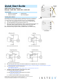
4) Connect wires per diagram which corresponds to your installation
Note: sense lines carry very low current (~0.35mA 240V, ~0.17mA for 120V)
5) After ensuring wires are firmly connected and that there is no exposed wire, turn on breaker/fuse
After a few seconds, load will turn on (if wired into switch or fixture) and Micro module LED will turn green
6) Test by tapping Micro module on/off buttons
Load will turn on and off
Micro Module LED will turn green when load is on and red when load is off
7) If installing a single momentary or dual momentary switch
a) Press and hold set button until it beeps
LED will start blinking green
b) Press and hold set button until it beeps a second time
LED will start blinking red
c) Press and hold set button until it beeps a third time
EU/AUS/NZ
North America
Sense #1
(yellow)
Sense #2
(purple)
LED
Antenna

2442-222, 2442-422, 2442-522 Rev. 6/3/2013 11:07 AM / See Owner’s Manual for Warranty Information.
Protected under U.S. and foreign patents (see www.insteon.com/patents)
© Copyright 2013 INSTEON, 16542 Millikan Ave., Irvine, CA 92606, 866-243-8022
LED will start blinking green
Perform the step that applies
• For single momentary: slowly tap set button four times
LED will continue blinking green
• For dual momentary: slowly tap set button five times
LED will start double-blinking green
• To switch back to latching: slowly tap set button six times
LED will start blinking green
e) Once the mode is selected, press and hold set button until it double-beeps
LED will stop blinking and turn green if load is on or red if load is off
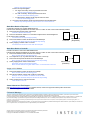
Make Micro Module a Responder
Control Micro module from another INSTEON device.
Perform before finalizing installation of the switch, fixture or outlet. Or refer to the manual if already installed.
1) Press and hold controller button until it beeps
Controller LED will start blinking
2) Press and hold Micro module on or off button to adjust load to desired brightness
(or off) when scene is activated
Connected load will respond appropriately
3) Press and hold Micro module set button until it double-beeps
Controller will double-beep and its LED will stop blinking
4) Test by tapping controller button on and off
Connected load will return to the state set in step #2
Make Micro Module a Controller
Use Micro module to control other INSTEON devices.
Perform before finalizing installation of the switch, fixture or outlet. Or refer to the manual if already installed.
1) Press and hold Micro module set button until it beeps
Micro module LED will start blinking green
2) Turn responder on (or any other state such as on 50% or even off)
3) Press and hold responder set button until it double-beeps
Micro module will double-beep and its LED will stop blinking
4) Test by tapping Micro module on/off buttons
Responder load will respond appropriately
Micro module LED will turn green when load is on and red when load is off
Assign an X10 Address
1) Press and hold Micro module set button until it beeps
Micro module LED will start blinking green
2) Send the X10 address 3 times (with or without commands)
Example: A1-A1-A1-AON or A1-AON-A1-AON-A1-AON
Micro module will double-beep and its LED will stop blinking
3) Test by sending X10 on and off commands
Load will turn on and off
Owner’s Manual and Tech Support
Visit: http://www.insteon.com/support for complete manual, online tech support and latest product documents.
Call: INSTEON Support Line at 866-243-8022
FCC and IC Warnings
This device complies with FCC Rules and Industry Canada license-exempt RSS standard(s). Operation is subject to the following two conditions: (1) this device may not cause harmful
interference, and (2) this device must accept any interference, including interference that may cause undesired operation of the device.
Le present appareil est conforme aux CNR d'Industrie Canada applicables aux appareils radio exempts de licence. L'exploitation est autorise aux deux conditions suivantes: (1) l'appareil ne doit
pas produire de brouillage, et (2) l'utilisateur de l'appareil doit accepter tout brouillage radiolectrique subi, mme si le brouillage est susceptible d'en compromettre le fonctionnement.
CAUTION - To reduce the risk of overheating and possible damage to other equipment do not install to control a receptacle, a motor-operated appliance, a fluorescent lighting fixture, or a
transformer-supplied appliance.
Gradateurs commandant une lampe a filament de tungstene – afin de reduire le risqué de surchauffe et la possibilite d’endommagement a d’autres materiels, ne pas installer pour commader une
prise, un appareil a moteur, une lampe fluorescente ou un appareil alimente par un transformateur.
Micro module
(Responder)
Controller
Micro module
(Controller)
Responder
-
 1
1
-
 2
2


INSTEON Remote Control Micro Dimmer Switch Adapter Guide de démarrage rapide
- Taper
- Guide de démarrage rapide
- Ce manuel convient également à
dans d''autres langues
Documents connexes
-
INSTEON Refurbished Remote Control 2-Wire Dimmer Switch Guide de démarrage rapide
-
-
-
-
-
-
-
-