Panasonic Panasonic PT-L520U Manuel utilisateur
- Catégorie
- Projecteurs de données
- Taper
- Manuel utilisateur

R
Before operating this product, please read the instructions carefully and save this
manual for future use.
LCD Projector
Operating Instructions
Model No. PT-L720U
PT-L520U
R
TQBJ 0104-2
Commercial Use

2 3
PreparationPreparation
IMPORTANT SAFETY NOTICE
WARNING:
TO REDUCE THE RISK OF FIRE OR ELECTRIC SHOCK, DO
NOT EXPOSE THIS PRODUCT TO RAIN OR MOISTURE.
Dear Panasonic Customer:
This instruction booklet provides all the necessary operating information that
you might require. We hope it will help you to get the most performance out
of your new product, and that you will be pleased with your Panasonic LCD
projector.
The serial number of your product may be found on its back. You should
note it in the space provided below and retain this booklet in case service is
required.
Model number: PT-L720U / PT-L520U
Serial number:
The lightning flash with arrowhead symbol, within an
equilateral triangle, is intended to alert the user to the
presence of uninsulated “dangerous voltage” within the
product’s enclosure that may be of sufficient magnitude to
constitute a risk of electric shock to persons.
The exclamation point within an equilateral triangle is
intended to alert the user to the presence of important
operating and maintenance (servicing) instructions in the
literature accompanying the product.
Power Supply: This LCD Projector is designed to operate on 100 V – 240 V, 50 Hz/60
Hz AC, house current only.
CAUTION: The AC power cord which is supplied with the projector as an accessory can
only be used for power supplies up to 125 V, 10 A. If you need to use higher
voltages or currents than this, you will need to obtain a separate 250 V
power cord. If you use the accessory cord in such situations, fire may result.
CAUTION: This equipment is equipped with a
three-pin grounding-type power
plug. Do not remove the grounding
pin on the power plug. This plug will
only fit a grounding-type power
outlet. This is a safety feature. If you
are unable to insert the plug into the
outlet, contact an electrician. Do not
defeat the purpose of the grounding
plug.
WARNING:
This equipment has been tested and found to comply with the limits for a
Class B digital device, pursuant to Part 15 of the FCC Rules. These limits
are designed to provide reasonable protection against harmful interference
in a residential installation. This equipment generates, uses, and can
radiate radio frequency energy and, if not installed and used in accordance
with the instructions, may cause harmful interference to radio
communications. However, there is no guarantee that interference will not
occur in a particular installation. If this equipment does cause harmful
interference to radio or television reception, which can be determined by
turning the equipment off and on, the user is encouraged to try to correct
the interference by one or more of the following measures:
– Reorient or relocate the receiving antenna.
– Increase the separation between the equipment and receiver.
– Connect the equipment into an outlet on a circuit different from that to
which the receiver is connected.
– Consult the dealer or an experienced radio/TV technician for help.
CAUTION: Any unauthorized changes or modifications to this equipment
will void the users authority to operate.
Do not remove
Declaration of Conformity
Model Number: PT-L720U / PT-L520U
Trade Name: Panasonic
Responsible party: Matsushita Electric Corporation of America.
Address: One Panasonic Way Secaucus New Jersey 07094
Telephone number: 1-800-528-8601 or 1-800-222-0741
Email: [email protected]
This device complies with Part 15 of the FCC Rules, Operation is subject to
the following two conditions: (1) This device may not cause harmful
interference, and (2) this device must accept any interference received,
including interference that may cause undesired operation.

5
Preparation
Precautions with regard to safety
WARNING
If a problem occurs (such as no image or no sound) or if you notice
smoke or a strange smell coming from the projector, turn off the power
and disconnect the power cord from the wall outlet.
B Do not continue to use the projector in such cases, otherwise fire or
electric shocks could result.
B Check that no more smoke is coming out, and then contact an Authorised
Service Center for repairs.
B Do not attempt to repair the projector yourself, as this can be dangerous.
Do not install this projector in a place which is not strong enough to
take the full weight of the projector.
B If the installation location is not strong enough, it may fall down or tip over,
and severe injury or damage could result.
Installation work (such as ceiling suspension) should only be carried
out by a qualified technician.
B If installation is not carried out correctly, there is the danger that injury or
electric shocks may occur.
If foreign objects or water get inside the projector, or if the projector is
dropped or the cabinet is broken, turn off the power and disconnect the
power cord from the wall outlet.
B Continued use of the projector in this condition may result in fire or electric
shocks.
B Contact an Authorised Service Center for repairs.
Do not overload the wall outlet.
B If the power supply is overloaded (for example, by using too many
adapters), overheating may occur and fire may result.
Do not remove the cover or modify it in any way.
B High voltages which can cause fire or electric shocks are present inside
the projector.
B For any inspection, adjustment and repair work, please contact an
Authorised Service Center.
Clean the power cord plug regularly to prevent it from becoming
covered in dust.
B If dust builds up on the power cord plug, the resulting humidity can
damage the insulation, which could result in fire. Pull the power cord out
from the wall outlet and wipe it with a dry cloth.
B If not using the projector for an extended period of time, pull the power
cord plug out from the wall outlet.
4
Contents
Preparation
IMPORTANT SAFETY NOTICE..........2
Precautions with regard to safety ....5
Accessories........................................9
Precautions on handling.................10
Location and function of each part...12
About the RGB INPUT indicator .....17
About the automatic setup function....17
Using the remote control unit.........18
Laser beam pointer.........................18
Wireless mouse ..............................19
Inserting the batteries .....................20
Operating range..............................20
Connections .....................................21
Notes on connections .....................21
Example of connecting to video
equipment ...................................22
Example of connecting to computer....23
Setting-up .........................................24
Projection methods.........................24
Projector position............................24
Projection distances .......................25
Basic Operation
Starting to use..................................26
Turning on the power......................26
Turning off the power......................27
On-screen menus.............................28
Menu screens .................................28
Menu operation guide.....................30
Unavailable on-screen menu
items............................................30
Returning to the previous screen....30
Returning a setting to the factory
default .........................................31
Using the freeze function................31
Using the D.ZOOM (digital zoom)
function .........................................32
Correcting keystone distortion.......33
Adjusting the picture.......................34
PICTURE MODE ............................34
Color Hue Setting ...........................34
COLOR...........................................35
TINT................................................35
BRIGHT ..........................................35
CONTRAST....................................35
SHARPNESS .................................35
Noise Reduction(NR)......................35
TV SYSTEM ...................................35
WHITE BALANCE R/G/B ...............36
SIGNAL MODE...............................36
Projecting sRGB-compatible
pictures........................................36
Adjusting the position.....................37
HORIZONTAL POSITION ..............37
VERTICAL POSITION....................37
DOT CLOCK...................................37
CLOCK PHASE ..............................37
ASPECT .........................................38
RESIZING.......................................39
Advanced Operation
Option settings.................................40
OSD................................................40
AUTO KEYSTN ..............................40
AUTO RGB IN ................................40
RGB2 SELECT...............................40
RGB Y·PB·PR.................................40
SXGA MODE..................................41
BACK COLOR ................................41
FRONT/REAR ................................41
DESK/CEILING ..............................41
FAN CONTROL..............................41
LAMP POWER ...............................41
LAMP RUNTIME ............................41
FUNC 1...........................................42
CONTROL KEY..............................42
Using the shutter function ..............42
Changing the display language......42
Using the INDEX WINDOW function...43
Using the SERIAL connector..........44
Others
Indicators..........................................46
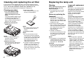
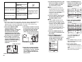
Cleaning and replacing the air filter...48
Replacing the lamp unit ..................49
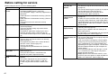
Before calling for service................52
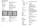
Specifications...................................54
List of compatible signals...............56
Dimensions.......................................57
Trademark acknowledgements ......57
NOTES IMPORTANTES
CONCERNANT LA SÉCURITÉ
...58
Précautions de sécurité
..............59
Précautions de manipulation
.............63
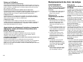
Remplacement du bloc de lampe
...65

7
Preparation
6
Do not look into the lens while the projector is being used.
B Strong light is emitted from the projector’s lens. If you look directly into this
light, it can hurt and damage your eyes.
Do not bring your hands or other objects close to the air outlet port.
B Heated air comes out of the air outlet port. Do not bring your hands or
face, or objects which cannot withstand heat close to this port, otherwise
burns or damage could result.
When replacing the lamp, allow it to cool for at least one hour before
handling it.
B The lamp cover gets very hot, and contact with it can cause burns.
Before replacing the lamp, be sure to unplug the power cord from the
power outlet.
B Electric shocks or explosions can result if this is not done.
Caution
Do not cover the air inlet or the air outlet.
B Doing so may cause the projector to overheat, which can cause fire or
damage to the projector.
Do not set up the projector in humid or dusty places or in places where
the projector may come into contact with smoke or steam.
B Using the projector under such conditions may result in fire or electric
shocks.
When disconnecting the power cord, hold the plug, not the cord.
B If the power cord itself is pulled, the cord will become damaged, and fire,
short-circuits or serious electric shocks may result.
Always disconnect all cables before moving the projector.
B Moving the projector with cables still attached can damage the cables,
which could cause fire or electric shocks to occur.
Do not place any heavy objects on top of the projector.
B Failure to observe this may cause the projector to become unbalanced
and fall, which could result in damage or injury.
Do not short-circuit, heat or disassemble the batteries or place them
into water or fire.
B Failure to observe this may cause the batteries to overheat, leak, explode
or catch fire, and burns or other injury may result.
When inserting the batteries, make sure the polarities (+ and -) are
correct.
B If the batteries are inserted incorrectly, they may explode or leak, and fire,
injury or contamination of the battery compartment and surrounding area
may result.
Do not do anything that might damage the power cord or the power
cord plug.
B Do not damage the power cord, make any modifications to it, place it near
any hot objects, bend it excessively, twist it, pull it, place heavy objects on
top of it or wrap it into a bundle.
B If the power cord is used while damaged, electric shocks, short-circuits or
fire may result.
B Ask an Authorised Service Center to carry out any repairs to the power
cord that might be necessary.
Do not handle the power cord plug with wet hands.
B Failure to observe this may result in electric shocks.
Insert the power cord plug securely into the wall outlet.
B If the plug is not inserted correctly, electric shocks or overheating could
result.
B Do not use plugs which are damaged or wall outlets which are coming
loose from the wall.
Do not place the projector on top of surfaces which are unstable.
B If the projector is placed on top of a surface which is sloped or unstable, it
may fall down or tip over, and injury or damage could result.
Do not place the projector into water or let it become wet.
B Failure to observe this may result in fire or electric shocks.
Do not place liquid containers on top of the projector.
B If water spills onto the projector or gets inside it, fire or electric shocks
could result.
B If any water gets inside the projector, contact an Authorised Service
Center.
Do not insert any foreign objects into the projector.
B Do not insert any metal objects or flammable objects into the projector or
drop them onto the projector, as doing so can result in fire or electric
shocks.
Keep the remote control unit out of the reach of children, and do not
look into the laser beam or point it towards other people.
B If the laser beam which is emitted by the remote control unit transmitter is
pointed directly into the eyes, it may cause visual ability to be impaired.
Do not allow the + and - terminals of the batteries to come into contact
with metallic objects such as necklaces or hairpins.
B Failure to observe this may cause the batteries to leak, overheat, explode
or catch fire.
B Store the batteries in a plastic bag and keep them away from metallic objects.
During a thunderstorm, do not touch the projector or the cable.
B Electric shocks can result.
Do not use the projector in a bath or shower.
B Fire or electric shocks can result.

9
Preparation
8
Use only the specified batteries.
B If incorrect batteries are used, they may explode or leak, and fire, injury or
contamination of the battery compartment and surrounding area may
result.
Do not mix old and new batteries.
B If the batteries are inserted incorrectly, they may explode or leak, and fire,
injury or contamination of the battery compartment and surrounding area
may result.
Do not put your weight on this projector.
B You could fall or the projector could break, and injury may result.
B Be especially careful not to let young children climb onto the projector.
Disconnect the power cord plug from the wall outlet as a safety
precaution before carrying out any cleaning.
B Electric shocks can result if this is not done.
Ask an Authorised Service Center to clean inside the projector at least
once a year.
B If dust is left to build up inside the projector without being cleaned out, it
can result in fire or problems with operation.
B It is a good idea to clean the inside of the projector before the season for
humid weather arrives. Ask your nearest Authorised Service Center to
clean the projector when required. Please discuss with the Authorised
Service Center regarding cleaning costs.
We are constantly making efforts to preserve and maintain a clean
environment. Please take non repairable units back to your dealer or a
recycling company.
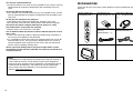
Remote control unit
(N2QAEA000008 x1)
Power cord
(K2CG3FZ00008 x1)
AAA batteries for
remote control unit (x2)
RGB signal cable [3.0 m
(9´10˝), K1HB15FA0001
x1]
Video/Audio cable [3.0
m (9´10˝),
K2KA2FA00001 x 1]
Accessories
Check that all of the accessories shown below have been included with your
projector.
Carrying bag (TPEP007
x1)
NOTICE:
B This product has a High Intensity Discharge (HID) lamp that contains a
small amount of mercury. It also contains lead in some components.
Disposal of these materials may be regulated in your community due to
environmental considerations. For disposal or recycling information
please contact your local authorities, or the Electronics Industries
Alliance: <http://www.eiae.org.>

11
Preparation
10
About the screen
If the screen you are using is dirty, damaged or discolored, attractive
projections cannot be obtained. Do not apply any volatile substances to the
screen, and do not let it become dirty or damaged.
About the lamp
The lamp may need to be replaced earlier due to variables such as a
particular lampís characteristics, usage conditions and the installation
environment, especially when it is subjected to a continuous use for more
than 10 hours.
Before carrying out cleaning and maintenance, be
sure to disconnect the power cord plug from the
wall outlet.
Wipe the cabinet with a soft, dry cloth.
If the cabinet is particularly dirty, soak the cloth in water with a small amount
of neutral detergent in it, squeeze the cloth very well, and then wipe the
cabinet. After cleaning, wipe the cabinet dry with a dry cloth.
If using a chemically-treated cloth, read the instructions supplied with
the cloth before use.
Do not wipe the lens with a cloth that is dusty or which produces lint.
If any dust or lint gets onto the lens, such dust or lint will be magnified and
projected onto the screen. Use a blower to clean any dust and lint from the
lens surface, or use a soft cloth to wipe off any dust or lint.
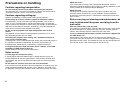
Precautions on handling
Cautions regarding transportation
Be sure to attach the lens cover before transporting the projector.
The projection lens is extremely susceptible to vibration and shocks. When
carrying the projector, use the accessory carrying bag.
Cautions regarding setting-up
Observe the following at all times when setting up the projector.
Avoid setting up in places which are subject to vibration or shocks.
If the projector is set up in locations with strong vibration, such as near a
motor, or if it is installed inside a vehicle or on board a ship, the projector
may be subjected to vibration or shocks which can damage the internal parts
and cause malfunctions or accidents. Accordingly, set up the projector in a
place which is free from such vibrations and shocks.
Do not set up the projector near high-voltage power lines or near
motors.
The projector may be subject to electromagnetic interference if it is set up
near high-voltage power lines or motors.
If installing the projector to the ceiling, ask a qualified technician to
carry out all installation work.
If the projector is to be suspended from the ceiling, you will need to purchase
the separate installation kit (Model No.: ET-PK730). Furthermore, all
installation work should only be carried out by a qualified technician.
If using this projector at high elevations (above 1 400 m), set the FAN
CONTROL to HIGH. (Refer to page 41.)
Failure to observe this may result in malfunctions.
Notes on use
In order to get the best picture quality
If outside light or light from indoor lamps is shining onto the screen, the
images projected will not have good contrast. Draw curtains or blinds over
any windows and turn off any fluorescent lights near the screen to prevent
reflection.
Do not touch the surfaces of the lens with your bare hands.
If the surface of the lens becomes dirty from fingerprints or anything else, this
will be magnified and projected onto the screen. Moreover, when not using
the projector, retract the lens and then cover it with the accessory lens cover.

13
Preparation
12
# Remote control signal receptor
(page 20)
$ Security lock
This can be used to connect a
commercially-available theft-
prevention cable (manufactured
by Kensington). This security lock
is compatible with the Microsaver
Security System from
Kensington. Contact details for
this company are given below.
Kensington Technology Group
ACCO Brands Inc.
2855 Campus Drive
San Mateo, CA 94403 USA
Tel (650)572-2700
Fax (650)572-9675
http://www.kensington.com/
http://www.gravis.com/
NOTE:
B Information given above may be
changed in future.
% Lamp unit holder
(page 49)
& Carrying handle
' Air outlet port
Do not cover this port.
When you change the direction of
the air flow out of the outlet port,
make sure that the MAIN
POWER is
“
OFF
”
and the
projector is cooled down.
WARNING
Do not bring your hands or other
objects close to the air outlet
port.
B Heated air comes out of the air
outlet port. Do not bring your
hands or face, or objects which
cannot withstand heat close to
this port, otherwise burns or
damage could result.
NOTE:
B During projection of an image, the
cooling fan will operate, emitting
a small noise as it operates.
Turning the lamp on or off will
cause this noise to increase a
little.
B By using the OPTION2 menu to
set “LAMP POWER” to
“
LOW
”
,
the operating sound of the fan
can be reduced. (Refer to page
41.)
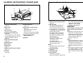
Projector <Back and bottom>
Location and function of each part
# Projector control panel
(page 14)
$ Focus ring
(page 27)
% Air inlet ports
Do not cover these ports.
& Leg adjuster buttons(L/R)
(page 26)
These buttons are used to unlock
the front adjustable legs. Press to
adjust the angle of tilt of the
projector.
' Front adjustable legs(L/R)
(page 26)
( Projection lens
) Lens cover
* Zoom knob
(page 27)
+ Remote control signal receptor
(page 20)
, Air filter
(page 48)
- Connector panel
(page 16)
. Power input socket (AC IN)
(page 26)
The accessory power cord is
connected here.
Do not use any power cord other
than the accessory power cord.
/ MAIN POWER switch
(pages 26 and 27)
0 Speaker
Projector <Top, right and front>
#
$
'
(
)
&
'+*
,
%
%
/
0
.
&
-
'#
$
%
&

15
Preparation
14
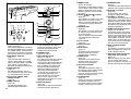
Remote control unit
# Power indicator
(pages 26 and 27)
This indicator illuminates red when
the MAIN POWER switch is turned
on (standby mode), and illuminates
green when the power is turned on
and a picture starts to be projected.
$ RGB INPUT indicator
(page 17)
This indicator shows whether a
signal is being input to the RGB
input connectors (RGB 1 IN/RGB
2 IN). When an input signal is
detected, the indicator illuminates.
% LAMP indicator
(page 47)
This indicator illuminates when it is
time to replace the lamp unit. It flashes
if a circuit abnormality is detected.
& Input select (INPUT, RGB,
VIDEO) buttons
(page 26)
' TEMP indicator
(page 46)
This indicator illuminates if an
abnormally high temperature is
detected inside the projector or around
it. If the temperature rises above a
certain level, the power supply will be
turned off automatically and the
indicator will illuminate or flash.
( POWER button
(pages 26 and 27)
) AUTO SETUP button
(pages 17 and 26)
If this button is pressed while a picture
is being projected, the projection
settings will be adjusted automatically
in accordance with the signal being
input. In addition, the angle of tilt of
the projector will be automatically
detected and adjusted in order to
correct any keystone distortion.
(“AUTO SETUP” will appear on the
screen during adjustment.) Set
“AUTO KEYSTN” in the OPTION1
menu to “OFF” to prevent any
deterioration of the picture as a result
of keystone correction.
* SHUTTER button
(page 42)
This button is used to momentarily
turn off the picture and sound.
+ MENU button
(pages 28 and 30)
This button is used to display the menu
screens. When a menu screen is being
displayed, this button can be used to
return to a previous screen or to clear
the screen.
, Arrow (
FFGGII
and
HH
) buttons
(page 30)
These buttons are used to select and
adjust items in the menu screens.
*When in computer operating mode,
these buttons function differently.
(page 19)
- ENTER button
(page 30)
This button is used to accept and
to activate items selected in the
on-screen menus.
*When in computer operating mode,
this button operates differently.
(page 19)
. Laser emitter
(page 18)
/ Infrared emitter
(page 20)
0 Click button
(page 19)
This button can be used when the
operating mode select switch is
moved to the left (Computer).
1 PAGE button
(page 19)
This button can be used when the
operating mode select switch is
moved to the left (Computer).
2 Operation indicator
(page 18)
This indicator illuminates while a
laser beam is being emitted (while
the LASER button is being
pressed). It flashes when any other
buttons are being pressed.
3 LASER button
(page 18)
A beam of laser light is emitted while
this button is being pressed. This
laser beam can be used as a pointer
to point to something on the screen.
4 FREEZE button
(page 31)
This button is used to momentarily freeze
projection so that a still picture is displayed.
5 D.ZOOM +/- buttons
(page 32)
These buttons are used to
enlarge the projected image.
6 VOLUME +/- buttons
These buttons are used to adjust the
volume of the sound output from the
projector’s built-in speaker. Refer to
page 28 for details on how to adjust
the volume using the buttons on the
projector control panel.
7 FUNCTION (FUNC1) button
(pages 33, 42 and 43)
This button is used to enter into the
keystone distortion correction mode,
and it can be used to split the screen
into one frozen image and one moving
image (INDEX menu item). Use the
FUNC1 item in the OPTION2 menu to
select which of these two operations
you want to use with this button.
8 STD (standard) button
(page 31)
This button is used to reset the
projector adjustment values to the
factory default settings.
9 Operating mode (Computer,
Projector) select switch
(page 19)
Move this switch to the left side to
use the remote control unit to
operate a computer, and move it to
the right side to operate the projector.
SHUTTERPOWER
AUTO SETUP
INPUT
TEMP
LAMPRGB INPUT
ENTER
MENU
ON(G)
STANDBY(R)
POWER
RGB
VIDEO
R-CLICK
LASER
MENU
PA GE
ENTER
FREEZE SHUTTER
FUNC1
Computer Pro jector
STD
SETUP
AUTO
(
&
)
2
3
+
1
,
-
4
*
8
5
6
7
9
.
(
/0
)
'
&
%
$
+,
-
*
#
Projector control panel

17
Preparation
16
<Connector panel>
&
% ' (
*
$#
)
# SERIAL connector
(pages 22, 23 and 44)
This connector is used to connect
a personal computer to the
projector in order to externally
control the projector. (RS-232C
compatible)
$ RGB1 IN connector
(pages 22 and 23)
This connector is used to input
RGB signals and YP
BPR signals.
% RGB2 IN/RGB1 OUT connector
(pages 22, 23 and 40)
This connector is used to input or
output RGB signals and YP
BPR
signals. Use the RGB2 SELECT
item in the OPTION1 menu to
select whether you want input or
output with this connector.
& AUDIO OUT jack
(pages 22 and 23)
This jack is used to output the
audio signals which are input to
the projector. If audio equipment
is connected to this jack, no
sound will be output from the
built-in speakers.
' S-VIDEO IN connector
(pages 22 and 38)
This connector is used to input
signals from a S-VIDEO-
compatible equipment such as a
video deck. The connector is S1
signal compatible, and it
automatically switches between
16:9 and 4:3 aspect ratios in
accordance with the type of
signal being input.
( VIDEO IN jack
(page 22)
This jack is used to input video
signals from a video equipment
such as a video deck.
) AUDIO IN L-R (for VIDEO/S-
VIDEO) jacks
(page 22)
Only one system is provided, so
connect the appropriate
connector when using VIDEO or
S-VIDEO.
* RGB AUDIO IN jack
(pages 22 and 23)
Only one system is provided, so
connect the appropriate
connector when using RGB1 or
RGB2.
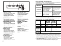
About the RGB INPUT indicator
The RGB INPUT indicator can be used to check whether an RGB/YPBPR
signal is being input. Refer to the table below for details.
RGB INPUT
indicator status
Power supply status
On (projecting)Standby
A signal is being input to
either the RGB1 IN or
RGB2 IN connector.
A signal is being input to
the connector selected
using the input select
buttons.
No signal is being input to
either the RGB1 IN or
RGB2 IN connector.
No signal is being input to
the connector selected
using the input select
buttons.
Illuminated
Switched off
About the automatic setup function
If you press the AUTO SETUP button, the items given in the table below will
be set automatically. The setting details change according to the signal
which is being input. Refer to the table below for details.
VIDEO/
S-VIDEO
YP
BPR
Dot Clock
frequency
is 100 MHz
or higher
Signal other
than above
Horizontal/
vertical
position
Dot clock/
clock phase
Auto RGB
input select
Automatic
keystone
correction
Yes
Yes
Yes
Yes
Yes No
NOTE:
B If the edges of the projected picture are indistinct, or if a dark picture is
being projected, the automatic setup processing may stop automatically
before it is complete. If this happens, project a different picture and then
press the AUTO SETUP button once more, or make the above
adjustments manually.
B If you would like to make further adjustments to the picture, use the menu
commands which are listed on page 28 and subsequent pages.

19
Preparation
18
Wireless mouse
By connecting the optional wireless mouse receiver (ET-RMRC1) to a
personal computer, it is possible to operate a personal computer, using
the remote control unit.
Connect the optional wireless receiver to a personal computer in the same
manner as connecting a mouse, to the USB port, PS/2 mouse port or ADB
port, using the cable provided with the wireless mouse receiver. (Refer to the
operating instructions of the wireless mouse receiver for details on how to
connect to a personal computer or on the types of personal computers that
can be used.)
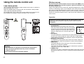
Using the remote control unit
P
U
S
H
Laser beam pointer
The laser beam emitted from the remote control can be used as a pointer by
pointing forward to the screen.
While the LASER button is being pressed, the laser beam is being emitted
and the operating indicator illuminates.
Do not look into the laser emitter of the remote control unit or point the laser
beam towards other people, otherwise damage to eyes may occur.
Caution
B Use of controls or adjustments or performance of procedures
other than those specified herein may result in hazardous
radiation exposure.
B This remote control unit cannot be repaired.
To operate a personal computer with the remote control, move the
operating mode (Computer, Projector) select switch to the left
(Computer).
Operation
B FGIHbuttons
While gently pressing the button with your thumb,
move your thumb up, down and to the left and right
to move the mouse cursor in the same direction. If
you press gently, the cursor will move slowly, and if
you press more firmly, the cursor will move more
quickly.
B Click button
The Click button on the underside of the remote control unit can be used
in place of the mouse button on a mouse with only a single button.
It corresponds to the left mouse button on a mouse with two buttons.
B ENTER (R-CLICK) button
The ENTER (R-CLICK) button at the front of the remote control unit
corresponds to the right mouse button on a mouse with two buttons.
B PAGE button
This button operates in the same way as the cursor up and down
buttons on the computer keyboard.
(Only when the wireless mouse receiver is connected to a personal
computer by means of the USB cable.)
B LASER button
A beam of laser light is emitted while this button is being pressed. This
beam of laser light can be used as a pointer by directing it toward the
screen.
Mouse cursor
N2QAEA000008

21
Preparation
20
B If there are any obstacles in between
the remote control unit and the
receivers, the remote control unit may
not operate correctly.
B
If strong light is allowed to shine onto
the remote control signal receiver,
correct remote control operation may
not be possible. Place the projector as
far away from light sources as possible.
B If facing the remote control unit
toward the screen to operate the
projector, the operating range of the
remote control unit will be limited by
the amount of light reflection loss
caused by the characteristics of the
screen used.
NOTE:
B If there are any obstacles in between
the remote control unit and the
receivers, the remote control unit may
not operate correctly.
B
If strong light is allowed to shine onto
the remote control signal receiver,
correct remote control operation may
not be possible. Place the projector as
far away from light sources as possible.
B If facing the remote control unit
toward the screen to operate the
projector, the operating range of the
remote control unit will be limited by
the amount of light reflection loss
caused by the characteristics of the
screen used.
B Do not drop the remote control unit.
B Keep the remote control unit away from liquids.
B Remove the batteries if not using the remote control unit for long periods.
B Do not use rechargeable batteries.
NOTE:
B Do not drop the remote control unit.
B Keep the remote control unit away from liquids.
B Remove the batteries if not using the remote control unit for long periods.
B Do not use rechargeable batteries.
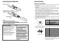
Operating range
If the remote control unit is held so
that it is facing directly in front of the
remote control signal receptors on
the front or rear of the projector, the
operating range is within
approximately 7 m (23´) from the
surfaces of the receptors.
Furthermore, the remote control unit
can be operated from an angle of
±30° to the left or right and ±15°
above or below the receptors.
# Open the cover.
AAA batteries
(two)
$ Insert the batteries so that the
polarities are correct, and then close the
cover.
Inserting the batteries Connections
Notes on connections
B Read the instruction manual for each system component carefully before
connecting it.
B Turn off the power supply for all components before making any
connections.
B If the cables necessary for connecting a component to the system are not
included with the component or available as an option, you may need to
fashion a cable to suit the component concerned.
B If there is a lot of jitter in the video signal which is input from the video
source, the picture on the screen may flicker. In such cases, it will be
necessary to connect a TBC (time base corrector).
B The projector has a built-in speaker. However, you will need to connect a
separate audio system to the AUDIO OUT jack if your needs specify high
sound volumes. No sound will come out of the projector’s built-in speaker
while the AUDIO OUT jack is being used.
B It may not be possible to connect some types of computer. Refer to the list
of compatible signals on page 56.
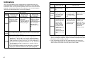
B The pin layout and signal names for the S-VIDEO IN connector are shown
below.
Pin No. Signal
#
Earth (Luminance signal)
Earth (Color signal)
Luminance signal
Color signal
$
%
&
B The pin layout and signal names for the RGB/YPBPR (RGB1 IN/RGB2 IN)
connector are shown below.
Pin No. Signal
#
R/P
R
G/G·SYNC/Y
B/P
B
SDA
$
%
.
/
HD/SYNC
0
VD
1
SCL
Pin + is spare.
Pins &–*, , and - are for earth.
Pins . and 1 functions are only valid when
supported by the computer
#$
%&
External view
-1
#'
,(
External view

23
Preparation
22
1 62 34 5
ON DIP
D-sub 9-pin
(male)
Computer for
control use
Computer
NOTE:
B It is better to shut down the computer before turning off the MAIN POWER
switch of the projector.
B Refer to the list of compatible signals on page 56 for the types of RGB
signals which can be input to the projector by connecting a computer.
B Do not input the signal to the RGB2 IN/RGB1 OUT connector when the
RGB2 SELECT item in the OPTION1 menu is set to OUTPUT. (Refer to
page 40.)
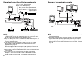
Example of connecting to computer
Monitor
Example of connecting with video equipments
D-sub 15 (male) - BNC5 (female)
adapter cable (sold separately)
Red (connect to P
R signal connector)
Blue (connect to PB signal connector)
Green (connect to Y signal connector)
Digital broadcast
tuner or DVD player
D-sub 9-pin
(male)
DVD player
Audio system
Video deck
NOTE:
B Only one audio system circuit is available for the AUDIO IN L-R jacks for
S-VIDEO/VIDEO signals, so if you wish to change the audio input source,
you will need to remove and insert the appropriate plugs.
B Only one audio system circuit is available for the RGB AUDIO IN jacks, so
if you wish to change the audio input source, you will need to remove and
insert the appropriate plugs.
B If an audio system is connected to the AUDIO OUT jack, the sound
volume balance can be controlled by the remote control unit which is
supplied with the projector.
B If the video signal source is connected using a cable with a BNC
connector plug, use a BNC/RCA adapter (sold separately) to convert the
cable end to an RCA plug-type jack.
B Refer to page 56 for a list of compatible YP
BPR signals which can be input
to the projector.
B If the signal cables are disconnected or if the power supply for the
computer or video deck is turned off while the digital zoom or index
window functions are being used, these functions will be cancelled.
Computer for
control use
Audio system

1.01 m(40˝) 0.61 m(2´) 0.81 m(2´8˝) 1.2 m(3´11˝) 1.5 m(4´11˝)
0.06 m(2-13/32˝)
1.27 m(50˝) 0.76 m(2´6˝) 1.02 m(3´4˝) 1.6 m(5´2˝) 1.9 m(6´2˝)
0.08 m(3˝)
1.52 m(60˝) 0.91 m(3´) 1.22 m(4´) 1.9 m(6´2˝) 2.3 m(7´6˝)
0.09 m(3-19/32˝)
1.77 m(70˝) 1.07 m(3´6˝) 1.42 m(4´8˝) 2.2 m(7´2˝) 2.7 m(8´10˝)
0.11 m(4- 6/32˝)
2.03 m(80˝) 1.22 m(4´) 1.63 m(5´4˝) 2.5 m(8´2˝) 3.1 m(10´2˝)
0.12 m(4-26/32˝)
2.28 m(90˝) 1.37 m(4´6˝) 1.83 m(6´) 2.8 m(9´2˝) 3.5 m(11´5˝)
0.14 m(5-13/32˝)
2.54 m(100˝) 1.52 m(5´) 2.03 m(6´8˝) 3.1 m(10´2˝) 3.9 m(12´9˝)
0.15 m(6˝)
3.81 m(150˝) 2.29 m(7´6˝) 3.05 m(10´) 4.7 m(15´5˝) 5.8 m(19´)
0.23 m(9˝)
5.08 m(200˝) 3.05 m(10´) 4.06 m(13´4˝) 6.2 m(20´4˝) 7.8 m(25´7˝)
0.31 m(12˝)
6.35 m(250˝) 3.81 m(12´6˝) 5.08 m(16´8˝) 7.8 m(25´7˝) 9.8 m(32´1˝)
0.38 m(15˝)
7.62 m(300˝) 4.57 m(15´) 6.10 m(20´) 9.4 m(30´10˝) 11.8 m(38´8˝)
0.46 m(18˝)
25
Preparation
24
Setting-up
Projection methods
In way of installing projector, any one of the following four projection methods
are used. Select whichever projection method matches the setting-up
method. (The projection method can be set from the OPTION2 menu. Refer
to page 41 for details.)
FRONT/REAR
FRONT
REAR
(Factory default setting)
NOTE:
B You will need to purchase the separate ceiling bracket (ET-PK730) when
using the ceiling installation method.
Projector position
DESK/CEILING
DESK CEILING
H1
L
L
SH
SW
9.6 (3/8)
L: Projection distance
SH: Image height
SW:Image width
H1: Distance from center
of lens to bottom edge
of projected image
Top edge of screen
Screen
Bottom edge of screen
Screen
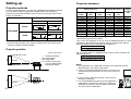
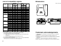
Projection distances
Setting-up dimensions which are not given in the above table can be
calculated using the formulas below.
If the screen size (diagonal) is SD (m), then the following formula is used to
calculate the projection distance for the wide lens position (LW) and the
projection distance for the telephoto lens position (LT).
For 16:9 aspect ratios, the following formula can be used to calculate the
projection distance.
NOTE:
B The dimensions in the table above and the values obtained from the
above formulas may contain slight errors.
B If you use the projection distance for the 16:9 screen, the
4:3 projection image overflows the screen at the top and
bottom.
B If you set up the projector vertically, it may cause to
damage the projector.
B
It is recommended that you set up the projector in
a place that is tilted at less than
±30°. Setting up
the projector in places that are tilted at more than
±30° may cause malfunctions.
Screen size (4:3)
Diagonal
length
Height
(SH)
Width
(SW)
Projection distance (L)
Height
position
(H1)
Wide
(LW)
Telephoto
(LT)
LW=0.034xSD/0.0254-0.068
LT=0.043xSD/0.0254-0.066
LW=0.031xSD/0.0254-0.068
LT=0.0393xSD/0.0254-0.066
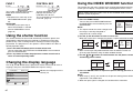
<Units: mm (inch)>

POWER
RGB
VIDEO
LASER
MENU
PAG E
SETUP
AUTO
SHUTTERPOWER
AUTO SETUP
INPUT
TEMP
LAMPRGB INPUT
ENTER
MENU
ON(G)
STANDBY(R)
Basic Operation
2726
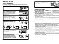
Starting to use
Turning on the power
Please ensure that all preparations have been completed before turning on
the power. (Refer to pages 21 – 25.)
$
%
POWER
RGB
VIDEO
LASER
MENU
PAG E
SETUP
AUTO
SHUTTERPOWER
AUTO SETUP
INPUT
TEMP
LAMPRGB INPUT
ENTER
MENU
ON(G)
STANDBY(R)
POWER
RGB
VIDEO
LASER
MENU
PAG E
SETUP
AUTO
SHUTTERPOWER
AUTO SETUP
INPUT
TEMP
LAMPRGB INPUT
ENTER
MENU
ON(G)
STANDBY(R)
# Remove the lens cover.
$ Connect the accessory power cord.
% Press the MAIN POWER switch to
the “|” side to turn on the power.
The power indicator on the projector
will illuminate red.
& Press the POWER button.
The power indicator on the projector
will flash green. After a short period,
the indicator will illuminate green, and
a picture will be projected.
' Press the input select (INPUT, RGB,
VIDEO) button to select the input
signal.
The input signal selected will change
as shown at below each time an input
select button is pressed.
Turning off the power
# Press the POWER button. “POWER OFF” is
displayed on the screen.
$ Select “OK” using the
II
and
HH
buttons and
press the ENTER button.
The lamp unit will switch off and the picture will stop being projected. (The
power indicator on the projector will illuminate orange.)
% Wait until the power indicator on the projector illuminates red (until
the cooling fan stops).
Do not in any way cut power to the projector while the cooling fan is still
operating. Be careful not to switch off the MAIN POWER switch of the
projector, unplug the power cord from the electrical outlet or turn off in-line
switches such as tabletop power switches.
& Press the MAIN POWER switch to the “O” side to turn off the power.
NOTE:
B After the power is turned off, the lamp unit will take some time to cool
down. If you turn the power back on again before the lamp unit has cooled
down, the lamp unit may not turn on straight away, but it will turn on
automatically after a short period. (During this time, the power indicator on
the projector will flash orange.)
B When the projector is in standby mode (the power indicator on the
projector is illuminated red), the projector will still draw a maximum 1.7 W
of power, even when the cooling fan has stopped.
B If the MAIN POWER switch is accidentally turned off while the projector is
being used, the lamp unit may not turn on straight away after the power is
turned back on. In such cases, the lamp unit will turn back on
automatically after a short period. (During this time, the power indicator on
the projector will flash green.)
B A tinkling sound may be heard while the power indicator is turned off, but
this is not a sign of a malfunction.
B You can also turn off the power by pressing the POWER button twice or
by holding down it for at least 0.5 seconds.
*Turn the focus ring and the zoom
knob to adjust the projected image
focus and size.
Zoom
Focus
( While pressing the adjuster buttons,
adjust the forward/back angle of tilt
of the projector.
INPUT RGB
VIDEO
) Press the AUTO SETUP button to
initiate automatic positioning.
If keystone distortion has not been
corrected to the optimum level, carry
out keystone correction as described
on page 33.
POWER OFF
OK CANCEL

29
Basic Operation
28
When an S-VIDEO/VIDEO signal
is being input
PICTURE
PICTURE MODE STANDARD
COLOR TEMP. STANDARD
BRIGHT 32
CONTRAST 32
SHARPNESS 0
W-BAL R 32
W-BAL G 32
W-BAL B 32
SIGNAL MODE SVGA
STANDARD
SELECT ADJ ESC
PICTURE
PICTURE MODE STANDARD
COLOR TEMP. STANDARD
COLOR 32
TINT 32
BRIGHT 32
CONTRAST 32
SHARPNESS 2
NR 1
TV-SYSTEM AUTO1
STANDARD
SELECT ADJ ESC
When a YPBPR signal is being
input
PICTURE
PICTURE MODE STANDARD
COLOR TEMP. STANDARD
COLOR 32
TINT 32
BRIGHT 32
CONTRAST 32
SHARPNESS 2
NR 1
SIGNAL MODE 525I
STANDARD
SELECT ADJ ESC
PICTURE menu (page 34)
When an RGB signal is being
input
When an S-VIDEO/VIDEO signal
is being input
POSITION
H-POSITION 64
V-POSITION 32
DOT CLOCK 32
CLOCK PHASE 16
ASPECT 4:3
RESIZING ON
STANDARD
SELECT ENTER ESC
POSITION
H-POSITION 32
V-POSITION 16
ASPECT 4:3
RESIZING ON
STANDARD
SELECT ENTER ESC
POSITION menu (page 37)
When an RGB/YPBPR signal is
being input
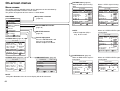
On-screen menus
Menu screens
The various settings and adjustments for this projector can be carried out by
selecting the operations from on-screen menus.
The general arrangement of these menus is shown below.
MAIN MENU
OPTION2 menu (page 40)
LANGUAGE menu (page 42)
SHUTTER function
(page 42)
NOTE:
B Keystone distortion of the on-screen display will not be corrected.
MENU
KEYSTONE
PICTURE
POSITION
INDEX WINDOW
SHUTTER
AUDIO
LANGUAGE
OPTION1
OPTION2
SELECT
ENTER
OPTION2
BACK COLOR BLUE
FRONT/REAR FRONT
DESK/CEILING DESK
FAN CONTROL STANDARD
LAMP POWER HIGH
LAMP RUNTIME 10H
FUNC 1 INDEX
CONTROL KEY ON
SELECT ADJ ESC
LANGUAGE ENGLISH
ENGLISH
DEUTSCH
FRANÇAIS
ESPAÑOL
ITALIANO
SELECT ENTER ESC
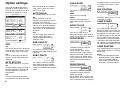
Keystone correction
(page 33)
OPTION1
OSD ON
AUTO KEYSTN ON
AUTO RGB IN ON
RGB2 SELECT INPUT
RGB/Y•PB•PR Y•PB•PR
SXGA MODE SXGA
SELECT ADJ ESC
OPTION1 menu (page 40)
INDEX WINDOW function
(page 43)
Volume adjustment
Press the ENTER button, and
then press the I and H
buttons to adjust the volume.
NOTE:
B Noise Reduction (NR) is
only for PT-L720U.

31
Basic Operation
30
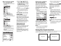
Returning a setting to
the factory default
If you press the STD (standard)
button on the remote control unit,
you can return settings to the
factory default settings. However,
the operation of this function varies
depending on which screen is being
displayed.
B When a menu screen is being
displayed
All items displayed will be returned
to their factory default settings,
“STD” will be displayed in the top-
right screen and the bar scale will
appear white.
NOTE:
B You can also select STANDARD
from the menu screen and then
press the ENTER button.
B When an individual adjustment
screen is being displayed
Only the item displayed will be
returned to the factory default
setting, and the bar scale will
appear white.
NOTE:
B Triangle symbols above and
below a menu bar indicate the
factory default setting. Items
which do not have these triangle
symbols cannot be returned to
the factory default setting.
Indicates the standard factory
default setting
Indicates the current adjustment
value
B The positions of triangle symbols
vary depending on the type of
signal being input.
Menu operation guide
# Press the MENU button.
The MAIN MENU screen will be
displayed.
$ Press the
FF
or
GG
arrow
buttons to select an item.
Selected items will be displayed
in blue.
% Press the ENTER button to
accept the selection.
The selected menu screen or
adjustment screen will then be
displayed.
(Example: PICTURE menu)
MENU
KEYSTONE
PICTURE
POSITION
INDEX WINDOW
SHUTTER
AUDIO
LANGUAGE
OPTION1
OPTION2
SELECT
ENTER
MENU
KEYSTONE
PICTURE
POSITION
INDEX WINDOW
SHUTTER
AUDIO
LANGUAGE
OPTION1
OPTION2
SELECT
ENTER
PICTURE
PICTURE MODE STANDARD
COLOR TEMP. STANDARD
COLOR 32
TINT 32
BRIGHT 32
CONTRAST 32
SHARPNESS 2
NR 1
TV-SYSTEM AUTO1
STANDARD
SELECT ADJ ESC
& Press the
FF
or
GG
buttons to
select an item, and then press
the
II
or
HH
buttons to change
or adjust the setting.
An individual adjustment screen
such as the one shown below will
be displayed for bar-scale items.
The bar scale will turn green
when any adjustment changes
the setting from the factory set
value.
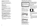
Unavailable on-screen
menu items
This projector has unadjustable
items and unusable functions
depending on the signal being input.
When an item cannot be adjusted or
a function cannot be used, the
corresponding on-screen menu
display does not appear, and the
item or function will not work even if
the ENTER button is pressed.
Returning to the
previous screen
If you press the MENU button while
a menu screen is being displayed,
the display will return to the
previous screen.
If you press the MENU button while
the MAIN MENU screen is being
displayed, the MAIN MENU screen
will be cleared.
BRIGHT 32
PICTURE STD
PICTURE MODE STANDARD
COLOR TEMP. STANDARD
COLOR 32
TINT 32
BRIGHT 32
CONTRAST 32
SHARPNESS 2
NR 1
TV-SYSTEM AUTO1
STANDARD
SELECT ENTER ESC
BRIGHT 32
Using the freeze function
The picture will alternate between a still picture and a moving picture each
time the FREEZE button on the remote control unit is pressed.
Still picture Moving picture

33
Basic Operation
32
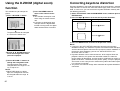
Using the D.ZOOM (digital zoom)
function
This function lets you enlarge the
picture.
# Press a D.ZOOM +/- button
[
The picture will then be enlarged
to 1.5 times the normal size.
$Use the F,G,IandHbuttons to
move the enlarged area which
you want to project.
& Press the MENU button to
return to the normal screen.
NOTE:
B This function can only be used
when using the remote control
unit.
B If the type of signal being input
changes while the digital zoom
function is being used, the digital
zoom function will be cancelled.
Correcting keystone distortion
Keystone distortion is corrected automatically when the projector’s automatic
setup function is used, but this correction will not apply if the screen itself is
tilted. In such cases, you can correct the keystone distortion manually with
the following procedure.
# Select “KEYSTONE” from the MAIN MENU screen, and then press the
ENTER button.
$ Press the
II
or
HH
buttons to correct the keystone distortion.
Picture condition Operation
Press the
HH
button.
Press the
II
button.
% Press the MENU button to return to the previous screen.
NOTE:
B If you press the AUTO SETUP button after correcting the keystone
distortion manually, the automatic keystone correction function will operate
and the corrected picture will return to its previous incorrect condition. To
prevent this from happening, you can set “AUTO KEYSTN” in the
OPTION1 menu to “OFF”.
B Keystone distortion can be corrected to ±30° of the angle of tilt for the
projector. However, the greater the correction amount, the more the
picture quality will deteriorate, and the harder it will become to achieve a
good level of focus. To obtain the best picture quality, set up the projector
and screen in such a way that the amount of keystone correction required
is as minimal as possible.
B The picture size will also change when correction of keystone distortion is
carried out.
% Use the D.ZOOM +/- buttons to
change the enlargement ratio.
The enlargement ratio can be
changed within the range of x1 to
x2, in steps of 0.1.
NOTE:
B When RGB signals are being
input, the enlargement ratio can
be changed within the range of
x1 to x3.

COLOR
(S-VIDEO/VIDEO/YPBPR only)
Press the H button to make the
color more vivid in tone, and press
the I button to make the color
more pastel in tone.
TINT
(NTSC/NTSC 4.43/YPBPR only)
This adjusts the flesh tones in the
picture. Press the H button to make
flesh tones more greenish, and
press the I button to make the
flesh tones more reddish.
BRIGHT
This adjusts the darker areas (black
areas) in the picture. Press the H
button if dark areas are too solid (for
example, if hair is difficult to see), and
press the I button if black areas are
too light (grey rather than black).
CONTRAST
This adjusts the contrast of the
picture. Press the H button to make
the picture brighter, and press the
I button to make the picture
darker. (Adjust the BRIGHT setting
first if required before adjusting the
CONTRAST setting.)
SHARPNESS
Press the H button to make the
picture details sharper, and press
the I button to make the picture
details softer.
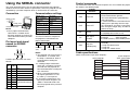
Noise Reduction (NR)
(Only for PT-L720U, when S-
VIDEO/VIDEO/YPBPR signals are
being input)
If the signal is of such poor quality
that picture interference appears, you
can suppress this interference by
adjusting the NR (Noise Reduction),
except for 750p (720p), HDTV60
Use the F and G buttons on the
projector or remote control unit to
select an item, and then use the I
and H buttons to change the setting
for that item.
For items with bar scales, press the
ENTER button or the I or H buttons
to display the adjustment screen, and
then use the I or H buttons to make
the adjustment.
When an S-VIDEO/VIDEO signal is being input
35
Basic Operation
34
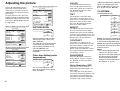
Adjusting the picture
COLOR TEMP. STANDARD
[
HIGH
[
LOW
PICTURE MODE STANDARD
[
DYNAMIC
[
NATURAL
PICTURE
PICTURE MODE STANDARD
COLOR TEMP. STANDARD
BRIGHT 32
CONTRAST 32
SHARPNESS 0
W-BAL R 32
W-BAL G 32
W-BAL B 32
SIGNAL MODE SVGA
STANDARD
SELECT ADJ ESC
PICTURE
PICTURE MODE STANDARD
COLOR TEMP. STANDARD
COLOR 32
TINT 32
BRIGHT 32
CONTRAST 32
SHARPNESS 2
NR 1
TV-SYSTEM AUTO1
STANDARD
SELECT ADJ ESC
When an RGB signal is being input
PICTURE
PICTURE MODE STANDARD
COLOR TEMP. STANDARD
COLOR 32
TINT 32
BRIGHT 32
CONTRAST 32
SHARPNESS 2
NR 1
SIGNAL MODE 525I
STANDARD
SELECT ADJ ESC
When an YPBPR signal is being input
PICTURE MODE
Select the picture mode that best
matches the image source and
room conditions.
The mode best used in dark rooms
is NATURAL. For rooms having
regular lighting conditions in use,
select STANDARD. For
exceptionally bright rooms, use
DYNAMIC.
This is used to adjust the white
areas of the picture if they appear
bluish or reddish.
Color Hue Setting (color
temperature)
AUTO1 The projector automatically
distinguishes between NTSC/NTSC
4.43/PAL/PAL60/SECAM signals.
AUTO2 The projector automatically
distinguishes between NTSC/PAL-
M/PAL-N signals.
NOTE:
B This should normally be set to
“AUTO1” or “AUTO2”. If the
signal is of such poor quality that
the correct format cannot be
automatically distinguished,
change the setting manually to
the required TV system.
TV SYSTEM AUTO1
[
AUTO2
[
NTSC
[
NTSC4.43
[
PAL
[
PAL-M
[
PAL-N
[
SECAM
TV SYSTEM
(S-VIDEO/VIDEO only)
(1080i/60) and HDTV50 (1080i/50)
signals. To strengthen the effect,
press the H button. To turn it off , set
to “0” by pressing the I button.

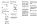
37
Basic Operation
36
Use the F and G buttons on the
projector or remote control unit to
select an item, and then use the I
and H buttons to change the setting
for that item.
For items with bar scales, press the
ENTER button or the I or H
buttons to display the adjustment
screen, and then use the I or H
buttons to make the adjustment.
When an RGB/YPBPR signal is
being input
When an S-VIDEO/VIDEO signal is
being input
HORIZONTAL POSITION
Press the I button to move the
picture to the left, and press the H
button to move the picture to the right.
VERTICAL POSITION
Press the I button to move the
picture down, and press the H
button to move the picture up.
DOT CLOCK
(RGB only)
Periodic striped pattern interference
(noise) may occur when a striped
pattern such as the one below is
projected. If this happens, use the
I and H buttons to adjust so that
any such noise is minimised.
CLOCK PHASE
(RGB/YPBPR only)
Adjust the DOT CLOCK setting first
before carrying out this adjustment.
Use the I and H buttons to adjust
so that the noise level is least
noticeable.
NOTE:
B
If signals with a dot clock frequency
of 100 MHz or higher are being input,
interference may not be completely
eliminated when the DOT CLOCK
and CLOCK PHASE adjustments are
carried out.
Adjusting the position
POSITION
H-POSITION 64
V-POSITION 32
DOT CLOCK 32
CLOCK PHASE 16
ASPECT 4:3
RESIZING ON
STANDARD
SELECT ENTER ESC
POSITION
H-POSITION 32
V-POSITION 16
ASPECT 4:3
RESIZING ON
STANDARD
SELECT ENTER ESC
When the input signal is RGB, first
press the AUTO SETUP button to
initiate automatic positioning.
If the optimum setting is not
obtained when AUTO SETUP is
carried out, adjust by the following
procedure.
WHITE BALANCE R/G/B
(RGB only)
This is used to adjust the white areas of the
picture if they appear colorised. Press the I
button to make the selected color lighter.
Press the H button to make the selected color
stronger.
SIGNAL MODE
(RGB/YPBPR only)
This displays the type of signal which is
currently being projected.
Refer to the table on page 56 for details on
each type of signal.
Projecting sRGB-compatible
pictures
sRGB is an international color reproduction
standard (IEC61966-2-1) established by the
International Electrotechnical Commission
(IEC). If you would like the colors in sRGB-
compatible pictures to be reproduced more
faithfully, make the following settings.
##
Press the
FF
or
GG
button to select
“PICTURE MODE”, and then use the
II
or
HH
button to select “NATURAL”.
$$
Press the STANDARD (STD) button on
the remote control unit.
%%
Press the
FF
or
GG
button to select
“COLOR TEMP.”, and then use the
II
or
HH
button to select “STANDARD”.
NOTE:
B sRGB is only enabled when RGB signals
are being input (when LAMP POWER has
been set to “HIGH”).

39
Basic Operation
38
S4:3
The size of the input signal is
compressed to 75% and projected.
(This is useful for projecting a
picture with a 4:3 aspect ratio onto a
16:9 screen.)
AUTO
(S-VIDEO only)
When an S1 video signal is input to
the S-VIDEO terminal, the aspect
ratio is changed automatically to
project a 16:9 picture.
4:3
The input signal is projected without
change.
16:9
The picture is compressed to a ratio
of 16:9 and projected.
ASPECT
This setting is only for an S-VIDEO/
VIDEO signal and a YPBPR signal in
525i (480i), 525p (480p) and 625i
format.
ASPECT AUTO
[
4:3
[
16:9
[
S4:3
NOTE:
B
This projector is equipped with an
aspect ratio selection function.
However, if a mode which does not
match the aspect ratio of the input
signal is selected, it may affect the
quality of viewing of the original
picture. Keep this in mind when
selecting the aspect ratio.
B
If using this projector in places such
as cafes or hotels with the aim of
displaying programs for viewing for a
commercial purpose or for public
presentation, note that if the aspect
ratio (16:9) selection function is used
to change the aspect ratio of the
screen picture, you may be infringing
the rights of the original copyright
owner for that program under
copyright protection laws.
B
If a normal (4:3) picture which was
not originally intended for wide-
screen viewing is projected onto a
wide screen, distortion may occur
around the edges of the picture so
that part of the picture is no longer
visible. Such programs should be
viewed in 4:3 mode to give proper
consideration to the aims and
intentions of the original program’s
creator.
S1 video signals
B
S1 video signals are a type of video
signal with an aspect ratio of 16:9
which include a detector signal. This
detector signal is output by some
sources such as wide-vision video
decks. If the AUTO setting above is
selected, this projector will recognise
the detector signal and automatically
switch the aspect ratio to 16:9 in
order to project the picture.
RESIZING
This should normally be set to “ON”.
(This setting is only for signals
which have lower resolutions than
the LCD panels. Refer to page 56
for details.)
ON
The pixel resolution of the input
signal is converted to the same
resolution as the LCD panels before
being projected. For signals with
lower resolutions, gaps in the pixels
are automatically interpolated into
the picture before it is projected.
This may sometimes cause
problems with the quality of the
picture.
OFF
The picture signal is projected at its
original resolution, with no pixel
conversion. The projected picture
will be smaller than normal, so
adjust the zoom setting or move the
projector forwards or backwards to
adjust the picture size if necessary.
If set to “OFF”, some features, such
as D.ZOOM (digital zoom),
keystone distortion correction or
INDEX WINDOW will not function.
When a squeezed
signal is being input.
(The projected
image is contracted
horizontally)
When a 4:3 signal
is being input
[
[
La page charge ...
La page charge ...
La page charge ...
La page charge ...
La page charge ...
La page charge ...
La page charge ...
La page charge ...
La page charge ...
La page charge ...
La page charge ...
La page charge ...
La page charge ...
La page charge ...
La page charge ...
-
 1
1
-
 2
2
-
 3
3
-
 4
4
-
 5
5
-
 6
6
-
 7
7
-
 8
8
-
 9
9
-
 10
10
-
 11
11
-
 12
12
-
 13
13
-
 14
14
-
 15
15
-
 16
16
-
 17
17
-
 18
18
-
 19
19
-
 20
20
-
 21
21
-
 22
22
-
 23
23
-
 24
24
-
 25
25
-
 26
26
-
 27
27
-
 28
28
-
 29
29
-
 30
30
-
 31
31
-
 32
32
-
 33
33
-
 34
34
-
 35
35


Panasonic Panasonic PT-L520U Manuel utilisateur
- Catégorie
- Projecteurs de données
- Taper
- Manuel utilisateur
dans d''autres langues
Documents connexes
-
Panasonic PTL785U Manuel utilisateur
-
Panasonic PT-LB51NTU Manuel utilisateur
-
-
-
-
-
-
-
-
Autres documents
-
Philips PT-LB51SU Manuel utilisateur
-
Proxima ASA DP6850 Manuel utilisateur
-
Hitachi CP-X960E Manuel utilisateur
-
Hitachi CPX970 Manuel utilisateur
-
 BOXLIGHT MP-650i Manuel utilisateur
-
Sanyo PLC-EF60A Quick Reference Manual
-
Sanyo PLC-SE10 Le manuel du propriétaire
-
Eiki LC-NB2 Manuel utilisateur
-
LG HX300G Le manuel du propriétaire
-
Christie 103-008100-01 Manuel utilisateur
