Lincoln Electric Bulldog 140 Manuel utilisateur
- Catégorie
- Système de soudage
- Taper
- Manuel utilisateur
Ce manuel convient également à

OPERATOR’S MANUAL
Safety Depends on You
Lincoln arc welding and cutting
equipment is designed and built
with safety in mind. However, your
overall safety can be increased by
proper installation ... and thought-
ful operation on your part. DO
NOT INSTALL, OPERATE OR
REPAIR THIS EQUIPMENT
WITHOUT READING THIS
MANUAL AND THE SAFETY
PRECAUTIONS CONTAINED
THROUGHOUT. And, most
importantly, think before you act
and be careful.
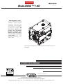
BULLDOG ™140
For Machines with Code Number 11518
IM10005
June, 2009
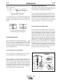
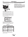
Various engine configurations are available and machine appearance will vary
accordingly.
ISO 9001
CERTIFICATE NUMBER: 30273
Designed and Manufactured Under a
Quality Program Certified by
ABS Quality Evaluations, Inc.
to ISO 9001 Requirements.
QMS
ANSI RAB
• Sales and Service through Subsidiaries and Distributors Worldwide •
Cleveland, Ohio 44117-1199 U.S.A. TEL: 216.481.8100 FAX: 216.486.1751 WEB SITE: www.lincolnelectric.com
• World's Leader in Welding and Cutting Products •
Copyright © Lincoln Global Inc.
RETURN TO MAIN MENU

FOR ENGINE
powered equipment.
1.a. Turn the engine off before troubleshooting and maintenance
work unless the maintenance work requires it to be running.
____________________________________________________
1.b.Operate engines in open, well-ventilated
areas or vent the engine exhaust fumes
outdoors.
____________________________________________________
1.c. Do not add the fuel near an open flame
welding arc or when the engine is running.
Stop the engine and allow it to cool before
refueling to prevent spilled fuel from vaporiz-
ing on contact with hot engine parts and
igniting. Do not spill fuel when filling tank. If
fuel is spilled, wipe it up and do not start
engine until fumes have been eliminated.
____________________________________________________
1.d. Keep all equipment safety guards, covers and devices in
position and in good repair.Keep hands, hair, clothing and
tools away from V-belts, gears, fans and all other moving
parts when starting, operating or repairing equipment.
____________________________________________________
1.e. In some cases it may be necessary to remove safety
guards to perform required maintenance. Remove
guards only when necessary and replace them when the
maintenance requiring their removal is complete.
Always use the greatest care when working near moving
parts.
___________________________________________________
1.f. Do not put your hands near the engine fan.
Do not attempt to override the governor or
idler by pushing on the throttle control rods
while the engine is running.
___________________________________________________
1.g. To prevent accidentally starting gasoline engines while
turning the engine or welding generator during maintenance
work, disconnect the spark plug wires, distributor cap or
magneto wire as appropriate.
i
SAFETY
i
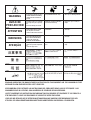
ARC WELDING CAN BE HAZARDOUS. PROTECT YOURSELF AND OTHERS FROM POSSIBLE SERIOUS INJURY OR DEATH.
KEEP CHILDREN AWAY. PACEMAKER WEARERS SHOULD CONSULT WITH THEIR DOCTOR BEFORE OPERATING.
Read and understand the following safety highlights. For additional safety information, it is strongly recommended that you
purchase a copy of “Safety in Welding & Cutting - ANSI Standard Z49.1” from the American Welding Society, P.O. Box
351040, Miami, Florida 33135 or CSA Standard W117.2-1974. A Free copy of “Arc Welding Safety” booklet E205 is available
from the Lincoln Electric Company, 22801 St. Clair Avenue, Cleveland, Ohio 44117-1199.
BE SURE THAT ALL INSTALLATION, OPERATION, MAINTENANCE AND REPAIR PROCEDURES ARE
PERFORMED ONLY BY QUALIFIED INDIVIDUALS.
WARNING
Mar ‘95
ELECTRIC AND
MAGNETIC FIELDS
may be dangerous
2.a. Electric current flowing through any conductor causes
localized Electric and Magnetic Fields (EMF). Welding
current creates EMF fields around welding cables and
welding machines
2.b. EMF fields may interfere with some pacemakers, and
welders having a pacemaker should consult their physician
before welding.
2.c. Exposure to EMF fields in welding may have other health
effects which are now not known.
2.d. All welders should use the following procedures in order to
minimize exposure to EMF fields from the welding circuit:
2.d.1.
Route the electrode and work cables together - Secure
them with tape when possible.
2.d.2. Never coil the electrode lead around your body.
2.d.3. Do not place your body between the electrode and
work cables. If the electrode cable is on your right
side, the work cable should also be on your right side.
2.d.4. Connect the work cable to the workpiece as close as
possible to the area being welded.
2.d.5. Do not work next to welding power source.
1.h. To avoid scalding, do not remove the
radiator pressure cap when the engine is
hot.
CALIFORNIA PROPOSITION 65 WARNINGS
Diesel engine exhaust and some of its constituents
are known to the State of California to cause can-
cer, birth defects, and other reproductive harm.
The engine exhaust from this product contains
chemicals known to the State of California to cause
cancer, birth defects, or other reproductive harm.
The Above For Diesel Engines
The Above For Gasoline Engines

ARC RAYS can burn.
4.a. Use a shield with the proper filter and cover
plates to protect your eyes from sparks and
the rays of the arc when welding or observing
open arc welding. Headshield and filter lens
should conform to ANSI Z87. I standards.
4.b. Use suitable clothing made from durable flame-resistant
material to protect your skin and that of your helpers from
the arc rays.
4.c. Protect other nearby personnel with suitable, non-flammable
screening and/or warn them not to watch the arc nor expose
themselves to the arc rays or to hot spatter or metal.
ELECTRIC SHOCK can
kill.
3.a. The electrode and work (or ground) circuits
are electrically “hot” when the welder is on.
Do not touch these “hot” parts with your bare
skin or wet clothing. Wear dry, hole-free
gloves to insulate hands.
3.b. Insulate yourself from work and ground using dry insulation.
Make certain the insulation is large enough to cover your full
area of physical contact with work and ground.
In addition to the normal safety precautions, if welding
must be performed under electrically hazardous
conditions (in damp locations or while wearing wet
clothing; on metal structures such as floors, gratings or
scaffolds; when in cramped positions such as sitting,
kneeling or lying, if there is a high risk of unavoidable or
accidental contact with the workpiece or ground) use
the following equipment:
• Semiautomatic DC Constant Voltage (Wire) Welder.
• DC Manual (Stick) Welder.
• AC Welder with Reduced Voltage Control.
3.c. In semiautomatic or automatic wire welding, the electrode,
electrode reel, welding head, nozzle or semiautomatic
welding gun are also electrically “hot”.
3.d. Always be sure the work cable makes a good electrical
connection with the metal being welded. The connection
should be as close as possible to the area being welded.
3.e. Ground the work or metal to be welded to a good electrical
(earth) ground.
3.f.
Maintain the electrode holder, work clamp, welding cable and
welding machine in good, safe operating condition. Replace
damaged insulation.
3.g. Never dip the electrode in water for cooling.
3.h. Never simultaneously touch electrically “hot” parts of
electrode holders connected to two welders because voltage
between the two can be the total of the open circuit voltage
of both welders.
3.i. When working above floor level, use a safety belt to protect
yourself from a fall should you get a shock.
3.j. Also see Items 6.c. and 8.
ii
SAFETY
ii
FUMES AND GASES
can be dangerous.
5.a.Welding may produce fumes and gases
hazardous to health. Avoid breathing these
fumes and gases. When welding, keep
your head out of the fume. Use enough
ventilation and/or exhaust at the arc to keep
fumes and gases away from the breathing zone. When
welding with electrodes which require special
ventilation such as stainless or hard facing (see
instructions on container or MSDS) or on lead or
cadmium plated steel and other metals or coatings
which produce highly toxic fumes, keep exposure as
low as possible and within applicable OSHA PEL and
ACGIH TLV limits using local exhaust or mechanical
ventilation. In confined spaces or in some circum-
stances, outdoors, a respirator may be required.
Additional precautions are also required when welding
on galvanized steel.
5. b. The operation of welding fume control equipment is affected
by various factors including proper use and positioning of
the equipment, maintenance of the equipment and the spe-
cific welding procedure and application involved. Worker
exposure level should be checked upon installation and
periodically thereafter to be certain it is within applicable
OSHA PEL and ACGIH TLV limits.
5.c.
Do not weld in locations near chlorinated hydrocarbon
vapors
coming from degreasing, cleaning or spraying operations.
The heat and rays of the arc can react with solvent vapors
to
form phosgene, a highly toxic gas, and other irritating prod-
ucts.
5.d. Shielding gases used for arc welding can displace air and
cause injury or death. Always use enough ventilation,
especially in confined areas, to insure breathing air is safe.
5.e. Read and understand the manufacturer’s instructions for this
equipment and the consumables to be used, including the
material safety data sheet (MSDS) and follow your
employer’s safety practices. MSDS forms are available from
your welding distributor or from the manufacturer.
5.f. Also see item 1.b.
Jan ‘09

FOR ELECTRICALLY
powered equipment.
8.a. Turn off input power using the disconnect
switch at the fuse box before working on
the equipment.
8.b. Install equipment in accordance with the U.S. National
Electrical Code, all local codes and the manufacturer’s
recommendations.
8.c. Ground the equipment in accordance with the U.S. National
Electrical Code and the manufacturer’s recommendations.
CYLINDER may explode
if damaged.
7.a. Use only compressed gas cylinders
containing the correct shielding gas for the
process used and properly operating
regulators designed for the gas and
pressure used. All hoses, fittings, etc. should be suitable for
the application and maintained in good condition.
7.b. Always keep cylinders in an upright position securely
chained to an undercarriage or fixed support.
7.c. Cylinders should be located:
•Away from areas where they may be struck or subjected to
physical damage.
•A safe distance from arc welding or cutting operations and
any other source of heat, sparks, or flame.
7.d. Never allow the electrode, electrode holder or any other
electrically “hot” parts to touch a cylinder.
7.e. Keep your head and face away from the cylinder valve outlet
when opening the cylinder valve.
7.f. Valve protection caps should always be in place and hand
tight except when the cylinder is in use or connected for
use.
7.g. Read and follow the instructions on compressed gas
cylinders, associated equipment, and CGA publication P-l,
“Precautions for Safe Handling of Compressed Gases in
Cylinders,” available from the Compressed Gas Association
1235 Jefferson Davis Highway, Arlington, VA 22202.
WELDING and CUTTING
SPARKS can
cause fire or explosion.
6.a.
Remove fire hazards from the welding area.
If this is not possible, cover them to prevent
the welding sparks from starting a fire.
Remember that welding sparks and hot
materials from welding can easily go through small cracks
and openings to adjacent areas. Avoid welding near
hydraulic lines. Have a fire extinguisher readily available.
6.b. Where compressed gases are to be used at the job site,
special precautions should be used to prevent hazardous
situations. Refer to “Safety in Welding and Cutting” (ANSI
Standard Z49.1) and the operating information for the
equipment being used.
6.c. When not welding, make certain no part of the electrode
circuit is touching the work or ground. Accidental contact
can cause overheating and create a fire hazard.
6.d. Do not heat, cut or weld tanks, drums or containers until the
proper steps have been taken to insure that such procedures
will not cause flammable or toxic vapors from substances
inside. They can cause an explosion even
though
they have
been “cleaned”. For information, purchase “Recommended
Safe Practices for the
Preparation
for Welding and Cutting of
Containers and Piping That Have Held Hazardous
Substances”, AWS F4.1 from the American Welding Society
(see address above).
6.e. Vent hollow castings or containers before heating, cutting or
welding. They may explode.
6.f.
Sparks and spatter are thrown from the welding arc. Wear oil
free protective garments such as leather gloves, heavy shirt,
cuffless trousers, high shoes and a cap over your hair. Wear
ear plugs when welding out of position or in confined places.
Always wear safety glasses with side shields when in a
welding area.
6.g. Connect the work cable to the work as close to the welding
area as practical. Work cables connected to the building
framework or other locations away from the welding area
increase the possibility of the welding current passing
through lifting chains, crane cables or other alternate cir-
cuits. This can create fire hazards or overheat lifting chains
or cables until they fail.
6.h. Also see item 1.c.
6.I. Read and follow NFPA 51B “ Standard for Fire Prevention
During Welding, Cutting and Other Hot Work”, available
from NFPA, 1 Batterymarch Park, PO box 9101, Quincy, Ma
022690-9101.
6.j. Do not use a welding power source for pipe thawing.
iii
SAFETY
iii
Jan ‘09
Refer to http://www.lincolnelectric.com/safety for additional safety information.

iv
SAFETY
iv
Mar. ‘93
PRÉCAUTIONS DE SÛRETÉ
Pour votre propre protection lire et observer toutes les instruc-
tions et les précautions de sûreté specifiques qui parraissent
dans ce manuel aussi bien que les précautions de sûreté
générales suivantes:
Sûreté Pour Soudage A L’Arc
1. Protegez-vous contre la secousse électrique:
a. Les circuits à l’électrode et à la piéce sont sous tension
quand la machine à souder est en marche. Eviter toujours
tout contact entre les parties sous tension et la peau nue
ou les vétements mouillés. Porter des gants secs et sans
trous pour isoler les mains.
b. Faire trés attention de bien s’isoler de la masse quand on
soude dans des endroits humides, ou sur un plancher
metallique ou des grilles metalliques, principalement dans
les positions assis ou couché pour lesquelles une
grande partie du corps peut être en contact avec la
masse.
c. Maintenir le porte-électrode, la pince de masse, le câble
de soudage et la machine à souder en bon et sûr état
defonctionnement.
d.Ne jamais plonger le porte-électrode dans l’eau pour le
refroidir.
e. Ne jamais toucher simultanément les parties sous tension
des porte-électrodes connectés à deux machines à soud-
er parce que la tension entre les deux pinces peut être le
total de la tension à vide des deux machines.
f. Si on utilise la machine à souder comme une source de
courant pour soudage semi-automatique, ces precautions
pour le porte-électrode s’applicuent aussi au pistolet de
soudage.
2. Dans le cas de travail au dessus du niveau du sol, se pro-
téger contre les chutes dans le cas ou on recoit un choc. Ne
jamais enrouler le câble-électrode autour de n’importe quelle
partie du corps.
3. Un coup d’arc peut être plus sévère qu’un coup de soliel,
donc:
a. Utiliser un bon masque avec un verre filtrant approprié
ainsi qu’un verre blanc afin de se protéger les yeux du
rayonnement de l’arc et des projections quand on soude
ou quand on regarde l’arc.
b. Porter des vêtements convenables afin de protéger la
peau de soudeur et des aides contre le rayonnement de
l‘arc.
c. Protéger l’autre personnel travaillant à proximité au
soudage à l’aide d’écrans appropriés et non-inflamma-
bles.
4. Des gouttes de laitier en fusion sont émises de l’arc de
soudage. Se protéger avec des vêtements de protection
libres de l’huile, tels que les gants en cuir, chemise épaisse,
pantalons sans revers, et chaussures montantes.
5. Toujours porter des lunettes de sécurité dans la zone de
soudage. Utiliser des lunettes avec écrans lateraux dans les
zones où l’on pique le laitier.
6. Eloigner les matériaux inflammables ou les recouvrir afin de
prévenir tout risque d’incendie dû aux étincelles.
7. Quand on ne soude pas, poser la pince à une endroit isolé de
la masse. Un court-circuit accidental peut provoquer un
échauffement et un risque d’incendie.
8. S’assurer que la masse est connectée le plus prés possible
de la zone de travail qu’il est pratique de le faire. Si on place
la masse sur la charpente de la construction ou d’autres
endroits éloignés de la zone de travail, on augmente le risque
de voir passer le courant de soudage par les chaines de lev-
age, câbles de grue, ou autres circuits. Cela peut provoquer
des risques d’incendie ou d’echauffement des chaines et des
câbles jusqu’à ce qu’ils se rompent.
9. Assurer une ventilation suffisante dans la zone de soudage.
Ceci est particuliérement important pour le soudage de tôles
galvanisées plombées, ou cadmiées ou tout autre métal qui
produit des fumeés toxiques.
10. Ne pas souder en présence de vapeurs de chlore provenant
d’opérations de dégraissage, nettoyage ou pistolage. La
chaleur ou les rayons de l’arc peuvent réagir avec les
vapeurs du solvant pour produire du phosgéne (gas forte-
ment toxique) ou autres produits irritants.
11. Pour obtenir de plus amples renseignements sur la sûreté,
voir le code “Code for safety in welding and cutting” CSA
Standard W 117.2-1974.
PRÉCAUTIONS DE SÛRETÉ POUR
LES MACHINES À SOUDER À
TRANSFORMATEUR ET À
REDRESSEUR
1. Relier à la terre le chassis du poste conformement au code
de l’électricité et aux recommendations du fabricant. Le dis-
positif de montage ou la piece à souder doit être branché à
une bonne mise à la terre.
2. Autant que possible, I’installation et l’entretien du poste
seront effectués par un électricien qualifié.
3. Avant de faires des travaux à l’interieur de poste, la
debrancher à l’interrupteur à la boite de fusibles.
4. Garder tous les couvercles et dispositifs de sûreté à leur
place.

vv
TThhaannkk YYoouu
for selecting a QUALITY product by Lincoln Electric. We want you
to take pride in operating this Lincoln Electric Company product
••• as much pride as we have in bringing this product to you!
Read this Operators Manual completely before attempting to use this equipment. Save this manual and keep it
handy for quick reference. Pay particular attention to the safety instructions we have provided for your protection.
The level of seriousness to be applied to each is explained below:
WARNING
This statement appears where the information must be followed exactly to avoid serious personal injury or loss of life.
This statement appears where the information must be followed to avoid minor personal injury or damage to this equipment.
CAUTION
Please Examine Carton and Equipment For Damage Immediately
When this equipment is shipped, title passes to the purchaser upon receipt by the carrier. Consequently, Claims
for material damaged in shipment must be made by the purchaser against the transportation company at the
time the shipment is received.
Please record your equipment identification information below for future reference. This information can be
found on your machine nameplate.
Product _________________________________________________________________________________
Model Number ___________________________________________________________________________
Code Number or Date Code_________________________________________________________________
Serial Number____________________________________________________________________________
Date Purchased___________________________________________________________________________
Where Purchased_________________________________________________________________________
Whenever you request replacement parts or information on this equipment, always supply the information you
have recorded above. The code number is especially important when identifying the correct replacement parts.
On-Line Product Registration
- Register your machine with Lincoln Electric either via fax or over the Internet.
• For faxing: Complete the form on the back of the warranty statement included in the literature packet
accompanying this machine and fax the form per the instructions printed on it.
• For On-Line Registration: Go to our
WEB SITE at www.lincolnelectric.com. Choose “Quick Links” and then
“Product Registration”. Please complete the form and submit your registration.
CUSTOMER ASSISTANCE POLICY
The business of The Lincoln Electric Company is manufacturing and selling high quality welding equipment, consumables, and cutting equip-
ment. Our challenge is to meet the needs of our customers and to exceed their expectations. On occasion, purchasers may ask Lincoln
Electric for advice or information about their use of our products. We respond to our customers based on the best information in our posses-
sion at that time. Lincoln Electric is not in a position to warrant or guarantee such advice, and assumes no liability, with respect to such infor-
mation or advice. We expressly disclaim any warranty of any kind, including any warranty of fitness for any customer’s particular purpose,
with respect to such information or advice. As a matter of practical consideration, we also cannot assume any responsibility for updating or
correcting any such information or advice once it has been given, nor does the provision of information or advice create, expand or alter any
warranty with respect to the sale of our products.
Lincoln Electric is a responsive manufacturer, but the selection and use of specific products sold by Lincoln Electric is solely within the control
of, and remains the sole responsibility of the customer. Many variables beyond the control of Lincoln Electric affect the results obtained in
applying these types of fabrication methods and service requirements.
Subject to Change – This information is accurate to the best of our knowledge at the time of printing. Please refer to www.lincolnelectric.com
for any updated information.

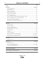
Page
Safety i-iv
Installation .............................................................................................................................Section A
Technical Specifications .............................................................................................................A-1
Safety Precautions......................................................................................................................A-2
Location and Ventilation .............................................................................................................A-2
Stacking, tilting and Lifting .........................................................................................................A-3
Pre-operation Engine Service .....................................................................................................A-3
Oil, Fuel and Spark Arrester........................................................................................................A-3
Electrical Output Connections and Welding Cable Size, Lengths..............................................A-4
Machine Grounding and Auxiliary Power Receptacles...............................................................A-5
Premises Wiring and Circuit Breakers ........................................................................................A-6
Electrical Devises used with the BULLDOG™ 140.....................................................................A-7
Operation...............................................................................................................................Section B
Safety Instructions ......................................................................................................................B-1
General Description ....................................................................................................................B-1
Recommended Applications.......................................................................................................B-1
Operational Features and Controls.............................................................................................B-1
Welding Capability......................................................................................................................B-1
Limitations .................................................................................................................................B-2
Controls and Settings .................................................................................................................B-2
Gasoline Engine Conrtols, Engine Operation ..............................................................B-3 Thru B-6
Welding Operation and Welding Guidelines..............................................................B-7 Thru B-16
Accessories...........................................................................................................................Section C
Options/Accessories ...................................................................................................................C-1
Maintenance..........................................................................................................................Section D
Safety Precautions......................................................................................................................D-1
Routine and Periodic Maintenance ..............................................................................D-1 thru D-4
General Assembly Exploded View..............................................................................................D-5
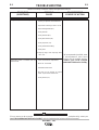
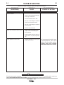
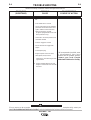
Troubleshooting and Repair ................................................................................................Section E
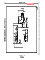
Electrical Diagram and Dimension Print.............................................................................Section F
Parts Manual (Robin / Subaru) ......................................................................................P-615 Series
TABLE OF CONTENTS
vi vi
BULLDOG™ 140

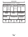
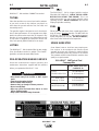
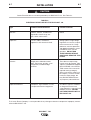
TECHNICAL SPECIFICATIONS - BULLDOG™ 140 K2708-1
Manufacturer Description Speed Displacement Ignition Capacities
Robin / Subaru 1 cyl., 3700 RPM 17.51 cu. in. Manual,
Fuel: 6.86 gal. (24.9 l)
EX 30 4 cycle ± 50 RPM (287 cc) Recoil start;
Code air-cooled at no load Manual choke Oil: 1.1 qts.(1.0 l)
(11518) OHC gasoline Bore x Stroke
10 HP @ 2.95” x 2.56”
3600 RPM (76mm x 65mm)
Aluminum Block
with Cast Iron
Sleeve
Duty Cycle Amps AC Volts at Rated Amperes
30% Duty Cycle 125 Amps AC Constant Current 20 VAC
60% Duty Cycle 100 Amps AC Constant Current 25 VAC
Welding Ranges Welder Open Circuit Voltage AC Auxiliary Power
70 - 140 Amps AC 66 VAC Max. 4000 Continuous Watts
5500 Surge Watts
Height Width Depth Weight
25.47 in. 21.12 in. 31.48 in. 205 lb.
646 mm 536.45 mm 799.59 mm 93 kg
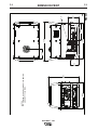
A-1
INSTALLATION
BULLDOG™ 140
A-1
INPUT - GASOLINE ENGINE
RATED OUTPUT - WELDER
OUTPUT - WELDER AND GENERATOR
PHYSICAL DIMENSIONS

A-2
INSTALLATION
BULLDOG™ 140
A-2
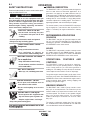
SAFETY PRECAUTIONS
Read this entire installation section before you
start installation.
Do not attempt to use this equipment until you
have thoroughly read all the operation and main-
tenance manuals supplied with your machine.
They include important safety precautions;
detailed engine starting, operating, and mainte-
nance instructions; and parts lists.
ELECTRIC SHOCK can kill.
• Do not touch electrically live
parts or electrodes with your
skin or wet clothing.
• Insulate yourself from the
work and ground.
•Always wear dry insulating gloves.
ENGINE EXHAUST can kill.
• Use in open, well ventilated
areas or vent exhaust to the
outside.
• Do not stack anything on or
near the engine.
MOVING PARTS can injure.
• Do not operate this equip-
ment with any of its doors
open or guards off.
• Stop the engine before ser-
vicing it.
• Keep away from moving parts.
Only qualified personnel should install, use, or service
this equipment.
LOCATION AND VENTILATION
Whenever you use the BULLDOG™ 140, be sure that
clean cooling air can flow through the machine’s
gasoline engine and the generator. Avoid dusty, dirty
areas. Also, keep the machine away from heat
sources. Do not place the back end of the generator
anywhere near hot engine exhaust from another
machine. And of course, make sure that engine
exhaust is ventilated to an open, outside area.
The BULLDOG™ 140 must be used outdoors. Do
not set the machine in puddles or otherwise sub-
merge it in water. Such practices pose safety haz-
ards and cause improper operation and corrosion of
parts.
Always operate the BULLDOG™ 140 with the case
roof on and all machine components completely
assembled. This will protect you from the dangers of
moving parts, hot metal surfaces, and live electrical
devices.
STORING
1. Store the machine in a cool, dry place when it’s
not in use. Protect it from dust and dirt. Keep it
where it can’t be accidentally damaged from con-
struction activities, moving vehicles, and other
hazards.
2. If you will be storing the machine for over 30
days, you should drain the fuel to protect fuel
system and carburetor parts from gum deposits.
Empty all fuel from the tank and run the engine
until it stops from lack of fuel.
3. You can store the machine for up to 24 months if
you use a gasoline stabilizing additive in the fuel
system. Mix the additive with the fuel in the tank
and run the engine for a short time to circulate
the additive through the carburetor.
4. While the engine is still warm, drain the oil and
refill with fresh oil per the engine manual.
5. Remove the spark plug and pour approximately
1/2 ounce (15 ml) of engine oil into the cylinder.
Replace the spark plug and crank the engine
slowly to distribute the oil.
6. Clean any dirt and debris from the cylinder and
cylinder head fins and housing, rotating screen,
and muffler areas.
7. Store in a clean, dry area.
WARNING

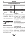
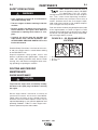
Robin / Subaru 10 HP Carb.
Certified
EX 30
.31 Gallons/Hour
(1.16 Liters/Hour)
.53 Gallons/Hour
(2.02 Liters/Hour)
.70 Gallons/Hour
(2.65 Liters/Hour)
No Load
3750 RPM ±100 R.P.M.
AC CC Weld Output
80 Amps @ 25 Volts
Auxiliary Power 4000
Watts (120/240 Volts)
BULLDOG™ 140 Typical Fuel
Consumption
A-3
INSTALLATION
BULLDOG™ 140
A-3
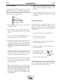
SPARK ARRESTER
Some federal, state or local laws may require gaso-
line engines to be equipped with exhaust spark
arresters when they are operated in certain locations
where unarrested sparks may present a fire hazard.
The standard muffler included with this machine does
qualify as a spark arrester.
WARNING
• Keep hands away from muffler or HOT engine
parts.
• Stop the engine when fueling.
• Do not smoke when fueling.
• Remove fuel cap slowly to release pressure.
• Do not overfill tank.
• Wipe up spilled fuel and allow fumes to clear
before starting engine.
• Keep sparks and flame away from tank.
------------------------------------------------------------------------
PRE-OPERATION ENGINE SERVICE
Read and understand the engine operating and
maintenance instructions supplied with this machine
before you operate the BULLDOG™ 140.
OIL
The BULLDOG™ 140 is shipped with the engine
filled with SAE 10W30 oil. CHECK THE OIL LEVEL
BEFORE YOU START THE ENGINE. This is an
added precaution. Do not screw in dipstick when
checking oil level. DO NOT OVERFILL. Be sure the
fill plug is tight after servicing.
FUEL
Fill the fuel tank with clean, fresh, regular grade (mini-
mum 87 octane lead free gasoline. DO NOT MIX OIL
WITH GAS. The BULLDOG™ 140 capacity is approxi-
mately 6.8 gallons (25.74 Liter). DO NOT OVERFILL,
allow room in the fuel tank for fuel expansion.
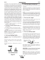
STACKING
BULLDOG™ 140 machines CANNOT be stacked.
TILTING
Place the machine on a secure, level surface whenev-
er you use it or store it. Any surfaces you place it on
other than the ground must be firm, non-skid, and
structurally sound.
The gasoline engine is designed to run in a level posi-
tion for best performance. It can operate at an angle,
but this should never be more than 15 degrees in any
direction. If you do operate it at a slight angle, be sure
to check the oil regularly and keep the oil level full.
Also, fuel capacity will be a little less at an angle.
LIFTING
The BULLDOG™ 140 should be lifted by two people.
(See Specification section for weight). The LowLift™
grab bars on both ends make lifting easier.

A-4
INSTALLATION
BULLDOG™ 140
A-4
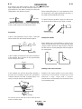
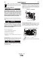
ELECTRICAL OUTPUT
CONNECTIONS
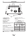
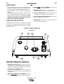
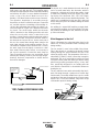
See Figure A.1 for the location of the current control
dial, weld output terminals, ground stud, circuit
breakers, 240 and 120 volt receptacles.
WELDING CABLE CONNECTIONS
Cable Size and Length
Be sure to use welding cables that are large enough.
The correct size and length becomes especially
important when you are welding at a distance from
the welder.
Table A.1 lists recommended cable sizes and lengths
for rated current and duty cycle. Length refers to the
distance from the welder to the work and back to the
welder. Cable diameters are increased for long cable
lengths to reduce voltage drops.
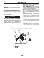
BULLDOG™ 140 OUTPUT CONNECTIONS
1. CURRENT CONTROL DIAL
2. WELD OUTPUT TERMINALS (2)
3. GROUND STUD
4. CIRCUIT BREAKER 20 Amp
5. RECEPTACLE - 240 VOLT, 50 AMP
6. DUPLEX RECEPTACLE (2)- 120 VOLT, 20
AMP
7. HOUR METER
FIGURE A.1
1
2
6
7
5
3
4
TOTAL COMBINED LENGTH OF
ELECTRODE AND WORK CABLES
Cable
Length
0-50 ft (0-15m)
50-100 ft (15-30 m)
100-150 ft (30-46 m)
150-200 ft (46-61 m)
200-250 ft (61-76m)
125 Amps
30% Duty Cycle
6 AWG
5 AWG
3 AWG
2 AWG
1 AWG
TABLE A.1
RECOMMENDED WELDING CABLE
SIZE AND LENGTH

A-5
INSTALLATION
BULLDOG™ 140
A-5
Cable Installation
Install the welding cables to your BULLDOG™ 140 as
follows. See Figure A.1 for the location of parts.
1. The gasoline engine must be OFF to install weld-
ing cables.
2. Remove the 1/2 - 13 flanged nuts from the output
terminals.
3. Connect the electrode holder and work cables to
the weld output terminals. You can connect either
cable to either terminal, since the BULLDOG™
140 provides AC weld current.
4. Tighten the flanged nuts securely.
5. Be certain that the metal piece you are welding
(the “work”) is securely connected to the work
clamp and cable.
6. Check and tighten the connections periodically.
• Loose connections will cause the output termi-
nals to overheat. The terminals may eventually
melt.
• Do not cross the welding cables at the output
terminal connection. Keep the cables isolated
and separate from one another.
-----------------------------------------------------------
Lincoln Electric offers a welding accessory kit with
the properly specified welding cables. See the
ACCESSORIES section of this manual for more infor-
mation.
ELECTRICAL CONNECTIONS
MACHINE GROUNDING
Because this portable engine driven welder creates its
own power, it is not necessary to connect its frame to
an earth ground, unless the machine is connected to
premises wiring (home, shop, etc.)
To prevent dangerous electric shock, other equipment
to which this engine driven welder supplies power
must:
1. Be grounded to the frame of the welder using a
grounded type plug.
2. Be double insulated.
Do not ground the machine to a pipe that carries
explosive or combustible material.
-----------------------------------------------------------------------
When the BULLDOG™ 140 is mounted on a truck or
a trailer, the machine generator ground stud MUST
be securely connected to the metal frame of the vehi-
cle. See Figure A.1. The ground stud is marked with
the symbol .
PLUGS AND HAND-HELD EQUIPMENT
For further protection against electric shock, any
electrical equipment connected to the generator
receptacles must use a three-blade, grounded type
plug or an Underwriter’s Laboratories (UL) approved
double insulation system with a two-blade plug.
Ground fault protection is recommended for hand
held equipment.
Never operate this machine with damaged or
defective cords. All electrical equipment must be
in safe condition.
-----------------------------------------------------------
AUXILIARY POWER RECEPTACLES
The control panel of the BULLDOG™ 140 features
two auxiliary power receptacles:
• A 20 amp, 120 volt duplex (double outlet) recepta-
cle
• A 20 amp 240 volt simplex (single outlet) recepta-
cle.
See Figure A.1.
Through these receptacles the machine can supply
up to 4,000 rated continuous watts and 5,500 surge
watts of single-phase AC power.
CAUTION
WARNING
WARNING

A-6
INSTALLATION
BULLDOG™ 140
A-6
PREMISES WIRING
The BULLDOG™ 140 is not recommended for
premises wiring.
The BULLDOG™ 140 does not have a combined
120/240 volt receptacle and cannot be connected to
a premises as described in other Lincoln literature.
Remember that the BULLDOG™ 140 is intended only
for backup, intermittent use power.
Certain electrical devices cannot be powered by the
BULLDOG™ 140. Refer to Table A.2 for these
devices.
CIRCUIT BREAKERS
Auxiliary power is protected by circuit breakers.
When the machine is operated in high temperature
environments, the breakers may tend to trip at lower
loads than normally.
Never bypass the circuit breakers. Without over-
load protection, the BULLDOG™ 140 could over-
heat and/or cause damage to the equipment being
used.
-------------------------------------------------------------
CAUTION

A-7
INSTALLATION
BULLDOG™ 140
A-7
CAUTION
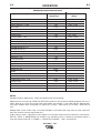
Certain Electrical devices cannot be powered by the BULLDOG™ 140. See Table A.2.
TABLE A.2
ELECTRICAL DEVICE USE WITH THE BULLDOG™ 140.
Type Common Electrical Devices Possible Concerns
Resistive Heaters, toasters, incandescent NONE
light bulbs, electric range, hot
pan, skillet, coffee maker.
Capacitive TV sets, radios, microwaves, Voltage spikes or high voltage
appliances with electrical control. regulation can cause the capaci-
tative elements to fail. Surge
protection, transient protection,
and additional loading is recom-
mended for 100% fail-safe
operation. DO NOT RUN
THESE DEVICES WITHOUT
ADDITIONAL RESISTIVE TYPE
LOADS.
Inductive Single-phase induction motors, These devices require large
drills, well pumps, grinders, small current inrush for starting. (See
refrigerators, weed and hedge Table B.3, GENERATOR POWER
trimmers APPLICATIONS, in the OPERA-
TION section of this manual for
required starting wattages.)
Some synchronous motors may
be frequency sensitive to attain
maximum output torque, but
they SHOULD BE SAFE from
any frequency induced failures.
Capacitive/Inductive Computers, high resolution TV sets, An inductive type line condition-
complicated electrical equipment. er along with transient and
surge protection is required, and
liabilities still exist. DO NOT
USE THESE DEVICES WITH A
BULLDOG™ 140.
The Lincoln Electric Company is not responsible for any damage to electrical components improperly connect-
ed to the BULLDOG™ 140.

B-1
OPERATION
B-1
SAFETY INSTRUCTIONS
Read and understand this entire section before oper-
ating your BULLDOG™ 140.
Do not attempt to use this equipment until you
have thoroughly read all the operation and main-
tenance manuals supplied with your machine.
They include important safety precautions;
detailed engine starting, operating, and mainte-
nance instructions; and parts lists.
ELECTRIC SHOCK can kill.
• Do not touch electrically live parts
or electrodes with your skin or wet
clothing.
• Insulate yourself from the work and ground.
• Always wear dry insulating gloves.
FUMES AND GASES can be
dangerous.
• Keep your head out of fumes.
• Use ventilation or exhaust to
remove fumes from breathing zone.
WELDING SPARKS can cause
fire or explosion.
• Keep flammable material away.
• Do not weld on containers that have
held combustibles.
ARC RAYS can burn.
• Wear eye, ear, and body protection.
ENGINE EXHAUST can kill.
• Use in open, well ventilated areas or
vent exhaust to the outside.
• Do not stack anything on or near the
engine.
MOVING PARTS can injure.
• Do not operate this equipment with
any of its doors open or guards off.
• Stop the engine before servicing it.
• Keep away from moving parts.
OOnnllyy qquuaalliiffiieedd ppeerrssoonnnneell sshhoouulldd iinnssttaallll,, uussee,, oorr sseerr--
vviiccee tthhiiss eeqquuiippmmeenntt..
GENERAL DESCRIPTION
The BULLDOG™ 140 is a generator/welder designed for
home use and other non-commercial applications. As a
generator it can supply up to 4,000 continuous watts (or
5,500 surge watts) of 120/240 volt, single-phase AC power.
As a welder it provides 125 amps of AC constant current for
welding with AC stick electrodes. A single dial provides
continuous adjustment of welding output. The machine is
lightweight, portable, and can be lifted by two people.
The Lincoln warranty covers the BULLDOG™ 140 (exclud-
ing the engine) for 3 years from the date of purchase. The
engine is covered by the engine manufacturer’s warranty
policy.
RECOMMENDED APPLICATIONS
GENERATOR
The BULLDOG™ 140 gives AC generator output for medi-
um use, non-commercial demands. For more details on
operating the generator, see GENERATOR OPERATION in
the OPERATION section of this manual.
WELDER
The BULLDOG™ 140 provides excellent constant current
AC welding output for stick (SMAW) welding. For more
details on using the machine as a welder, see WELDING
OPERATION in the OPERATION section of this manual.
OPERATIONAL FEATURES AND
CONTROLS
The BULLDOG™ 140 was designed for simplicity.
Therefore, it has very few operating controls. A single dial
on the control panel lets you select either generator or
welding use. For welding, the same dial selects continuous
current output over the machine’s 70 to 125 amp range.
The gasoline engine controls include a recoil starter, choke,
and rotary stop switch. See ENGINE OPERATION in the
OPERATION section of this manual and the engine owner’s
manual for details about starting, running, stopping, and
breaking in the gasoline engine.
WELDING CAPABILITY
The BULLDOG™ 140 is rated 125 amps, 20 volts at 30%
duty cycle on a ten-minute basis. This means that you can
load the welder to 125 amps for three minutes out of every
ten-minute period. The machine is also capable of higher
duty cycles at lower output currents. You can load the
welder to 100 amps for six minutes out of ten for a 60%
duty cycle.
The current is continuously variable from 70 to 125 amps
AC. The BULLDOG™ 140 can weld with all
3/32 and most
1/8 inch diameter Lincoln AC electrodes.
BULLDOG™ 140
WARNING

B-2
OPERATION
B-2
LIMITATIONS
• The BULLDOG™ 140 is not recommended for any
processes besides those that are normally per-
formed using stick welding (SMAW) procedures.
• The BULLDOG™ 140 is not recommended for pipe
thawing.
• During welding, generator power is limited to 100
watts, and output voltages can drop from 120 to 80
volts and 240 to 160 volts. Therefore, DO NOT
OPERATE ANY SENSITIVE ELECTRICAL EQUIP-
MENT WHILE YOU ARE WELDING.
BULLDOG™ 140
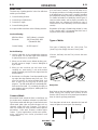
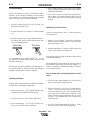
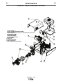
CONTROLS AND SETTINGS
All welder/generator controls are located on the Output
Control Panel. Gasoline engine controls are mounted on
the engine. See Figure B.1 and the figures in engine
operation section.
WELDER/GENERATOR CONTROLS
See Figure B.1 for the location of the following features:
1. CURRENT CONTROL DIAL: Adjusts continuous
current output. The amperages on the dial corre-
spond to the approximate amperages needed for
specific Lincoln welding electrodes.
2. 20 AMP CIRCUIT BREAKER: Provide separate over-
load current protection for the 120 Volt and 240 Volt
Receptacles
3. WELD ELECTRODE OUTPUT TERMINAL: Pro vides
the connection point for the electrode holder cable.
4. WELD WORK OUTPUT TERMINAL: Provides the
connection point for the work cable.
5. GROUND STUD: Provides a connection point for
connecting the machine case to earth ground.
6. 240 VOLT RECEPTACLE: Connection point for sup
240 Volt power to operate one electrical device.
7. 120 VOLT DUPLEX RECEPTACLES (2): Connection
point for supplying 120 Volt power.
8. HOUR METER: Records the time that the engine has
run for maintenance purposes.
1
2
6
7
8
5
3
4
OUTPUT PANEL CONTROLS
FIGURE B.1

B-3
OPERATION
B-3
BULLDOG™ 140
GASOLINE ENGINE CONTROLS
Refer to your engine manual for the location of the
following features:
1. FUEL SHUTOFF VALVE: Stops the flow of gaso-
line from the fuel tank to the carburetor. Should
be closed whenever you are finished using the
BULLDOG™ 140. Must be opened before you
start the engine.
2. FUEL TANK AND CAP: See TECHNICAL SPECI-
FICATIONS for capacity.
NOTE: If you use any other alternate fuel tank or
supply, be sure to use a recommended in-
line fuel filter.
3. MUFFLER: Reduces engine noise output.
See SPARK ARRESTER in the INSTALLATION
section of this manual.
4. “ON/OFF Switch: A two position switch located
on the rear of the engine. In the “ON”(I) position,
the engine ignition circuit is energized and the
engine can be started by pulling the recoil rope
starter. In the “OFF”(O) position, the electronic
ignition is grounded and the engine shuts down.
5. AIR CLEANER: Filters intake air to the carburetor.
See ENGINE MAINTENANCE in the MAINTE-
NANCE section of the engine owner’s manual for
details about the specific type of air cleaner to
use.
6. CHOKE: Provides a richer air/fuel mix-
ture for cold engine starting condi-
tions. See the topic ENGINE OPERA-
TION, below, for details on setting the
choke.
7. RECOIL STARTER: Manual, rope-type starter.
The handle position allows easy starting from
either ground level or pickup-truck level
8. OIL DRAIN PLUG: Permits convenient draining of
engine oil during maintenance. Both sides of the
engine are equipped with an oil drain plug.
9. OIL FILL PLUG: Permits convenient filling of
engine oil during maintenance. Both sides of the
engine are equipped with an oil fill plug.
ENGINE OPERATION
DO NOT RUN THE ENGINE AT EXCESSIVE
SPEEDS. The maximum allowable high idle speed
for the BULLDOG™ 140 is 3750 RPM, no load. Do
NOT adjust the governor screw on the engine.
Severe personal injury and damage to the
machine can result if it is operated at speeds
above the maximum rated speed.
-------------------------------------------------------------
Read and understand all safety instructions included
in the engine manufacturer’s Operating and
Maintenance Instructions manual that is shipped
with the BULLDOG™ 140.
WARNING

4. Pull the cord rapidly.
5. If the engine does not start, open the choke
slightly and pull the starter cord rapidly again.
When the engine starts, gradually open the choke
to the “RUN” position. To open the choke fully
requires an engine warm-up period of several
seconds to several minutes, depending on the
temperature. After starting the engine, first open
the choke (toward RUN) until the engine just
begins to run smoothly. Then open the choke in
small steps, allowing the engine to accept small
changes in speed and load, until the choke is fully
open (in RUN). During engine warm-up the equip-
ment can be operated.
FOR A “HOT” ENGINE:
1. Open the fuel shutoff valve.
2. Place the choke lever in the “RUN”
position. Closing the choke of a hot
engine will flood the carburetor and
prevent starting.
3. Pull slightly on the recoil starter handle until resis-
tance is felt.
4. Pull the cord rapidly.
FOR BEST ENGINE STARTING:
• Always use fresh gasoline and be sure the filter is
clean and properly maintained.
• If you use an alternate fuel tank or supply, be sure
to install an in-line fuel filter.
• Do not pull the recoil starter with the
choke in the “CHOKE” position more
than one time. Repeated pulls on a
choked engine will flood the carburetor.
• If the engine will not start, see the TROU-
BLESHOOTING section of this or the engine
owner’s manual.
B-4
OPERATION
B-4
BEFORE STARTING THE ENGINE
CHECK AND FILL THE ENGINE OIL LEVEL:
1. Place the machine on a level
surface.
2. Open the oil fill plug.
3. Fill (if necessary) until oil flows out the top of the
fill plug hole.
4. Replace the fill plug and tighten securely.
CHECK AND FILL THE ENGINE FUEL TANK:
1. Remove the fuel tank cap.
2. Fill the tank to allow approximately 1/4
inch (5 mm) of tank space for fuel
expansion. DO NOT FILL THE TANK
TO THE POINT OF OVERFLOW.
3. Replace the fuel tank cap and tighten securely.
NOTE: The engine will operate satisfactorily on any
gasoline meant for automotive use. A mini-
mum of 87 octane is recommended. DO NOT
MIX OIL WITH THE GASOLINE.
Use clean, fresh, lead-free gasoline. Leaded gasoline
may be used if lead-free is not available. However,
lead-free gasoline leaves fewer combustion deposits
and gives longer valve life. Purchase gasoline in
quantities that will be used within 30 days, to assure
freshness.
NOTE: We DO NOT recommend using gasoline that
contains alcohol, such as gasohol. However,
if gasoline with alcohol is used, it MUST NOT
contain more than 10% Ethanol and MUST
be removed from the engine during storage.
DO NOT use gasoline containing Methanol.
STARTING THE ENGINE
NOTE: Remove all loads connected to the AC power
receptacles before starting the gasoline
engine. Put the “ON/OFF” Switch in the
“ON”(I) position.
FOR A “COLD” ENGINE:
1. Open the fuel shutoff valve.
2. Place the choke lever in the “CHOKE”
position.
3. Pull slightly on the recoil starter handle until resis-
tance is felt.
BULLDOG™ 140

GENERATOR OPERATION
Be sure that any electrical equipment plugged into
the generator’s AC power receptacles can with-
stand a ±10% voltage and a ±4% frequency varia-
tion. Some electronic devices cannot be powered
by the BULLDOG™ 140. Refer to Table A.2, ELEC-
TRICAL DEVICE USE WITH THE BULLDOG™ 140,
in the INSTALLATION section of this manual.
-------------------------------------------------------------
GENERAL INFORMATION
The BULLDOG™ 140 generator is rated at 4000 con-
tinuous watts (5500 surge watts). It provides both
120 volt and 240 volt power. You can draw up to 20
amps from either side of the 120 volt duplex recepta-
cle, but no more than 33.3 amps from both sides at
once. Up to 16.7 amps can be drawn from the single
240 volt receptacle.
Electrical loads in watts are approximately calculated
by multiplying the voltage rating of the load by the
number of amps it draws. (This information is given
on the load device nameplate.) For example, a
device rated 120 volts, 2 amps will need 240 watts of
power (120 x 2 = 240).
You can use Table B.1, GENERATOR POWER APPLI-
CATIONS, to determine the wattage requirements of
the most common types of loads you can power with
the BULLDOG™ 140. Be sure to read the notes at
the bottom of the table.
TO USE THE BULLDOG™ 140 AS AN AUXILIARY
POWER SUPPLY:
1. Start the gasoline engine. See ENGINE OPERA-
TION in this section of the manual and the engine
owner’s manual.
2. Set the current control dial on the output control
panel to “GENERATOR”. See Figure B.1.
3. Plug the load(s) into the appropriate 120 volt or
240 volt power receptacle.
NOTE: During welding, the maximum generator out-
put for auxiliary loads is 100 watts.
NOTE: You can supply multiple loads as long as the
total load does not exceed 5,500 surge watts
or 4,000 Continuous watts. Be sure to start
the largest loads first.
CAUTION
B-5
OPERATION
B-5
STOPPING THE ENGINE
1. Remove all welding and generator power loads
and let the engine cool by running it for several
minutes.
2. Stop the engine by placing the “ON/OFF” switch
in the “OFF”(O) position.
3. Close the fuel shutoff valve.
Close the fuel valve when the machine is trans-
ported to prevent fuel leakage from the carbure-
tor.
For long periods of storage, turn off the fuel shut-
off valve and let the engine run until there is no
more fuel in the line. Use a fuel additive such as
Sta-Bil to minimize fuel gum deposits.
-------------------------------------------------------------
RUNNING THE ENGINE
The engine is set at the factory to run at high idle
speed when not under load. You should not adjust
this setting yourself.
BREAK-IN PERIOD
The engine will use a greater amount of oil during its
“break-in” period. Check the oil frequently during
break-in. For more details, see the MAINTENANCE
section in the engine owner’s manual.
During break-in, the unit should be subjected to
moderate loads. Before stopping the engine,
remove all loads and allow the engine to cool sev-
eral minutes.
-------------------------------------------------------------
LOW OIL SENSING
This engine has a built in sensor which responds to
low oil level (not pressure). When activated, the syst-
tem will shut the engine down. The engine will not
restart untill sufficient oil is added. Check oil level fre-
quently and add oil as required to the full mark on the
dipstick. (DO NOT OVERFILL)
BULLDOG™ 140
CAUTION
WARNING

TABLE B.1
GENERATOR POWER APPLICATIONS
Suggested Power Applications Running Watts *Start-up Watts
(Continuous) (Surge)
*Air Compressor - 1 HP 2,000 4,000 - 8,000
*Air Compressor - 3/4 HP 1,250 3,100 - 5,000
*Airless Sprayer - 1/3 HP 600 1,500 - 2,400
Chain Saw 1,200
Circular Saw 1,200
Coffee Maker 1,000
*Deep Freezer 500 750 - 2,000
*Electric Motor - 1 HP 1,000 2,500 - 4,000
Electric Range (1 element) 1,500
Electric Skillet 1,250
*Furnace Fan - 1/3 HP 1,200 3,000 - 4,800
Portable Grinder (4 1/2”) 600
Portable Grinder (7”) 2,000
Halogen Work Light 500
Hand Drill - 1/4” 500
Hand Drill - 3/8” 700
1500 Watt Heater 1,500
Hedge Trimmer 450
Light Bulb 100
Reciprocating Saw 900
Radial Arm Saw 2,600
Radio 50
*Refrigerator/Freezer (small) 600 1,500 - 2,400
Slow Cooker 200
*Submersible Pump - 1 HP 1,000 2,500 - 4,000
*Sump Pump 600 1,500 - 2,400
Toaster 1,100
Weed Trimmer 500
Lincoln Wire Feeder/Welder 4,000
B-6
OPERATION
B-6
BULLDOG™ 140
NOTES:
Wattages listed are approximate. Check your equipment for actual wattage.
Equipment with unusually high *START-UP WATTS are listed. For start-up of other tabled equipment that uses a
motor, allow up to 2 times the running watts shown above. For example a 1 HP motor requires approximately
1000 watts of power when running but may require (2.5 X 1000) = 2500 watts or (4.0 X 1000) = 4000 watts to
start.
Multiple loads can be used as long as the total load does not exceed 5,500 surge watts or 4,000 continuous
watts. Be certain to start the largest loads first.
Output rating in watts is equivalent to volt-amperes at unity power factor (resistive load) and is calculated as:
WATTS = VOLTS X AMPS DRAWN. for example a 120 volt device which is rated on its nameplate to draw 2
amps will need (120 VOLTS) X (2 AMPS) = 240 WATTS OF POWER. 1 KW = 1000 WATTS.
La page est en cours de chargement...
La page est en cours de chargement...
La page est en cours de chargement...
La page est en cours de chargement...
La page est en cours de chargement...
La page est en cours de chargement...
La page est en cours de chargement...
La page est en cours de chargement...
La page est en cours de chargement...
La page est en cours de chargement...
La page est en cours de chargement...
La page est en cours de chargement...
La page est en cours de chargement...
La page est en cours de chargement...
La page est en cours de chargement...
La page est en cours de chargement...
La page est en cours de chargement...
La page est en cours de chargement...
La page est en cours de chargement...
La page est en cours de chargement...
La page est en cours de chargement...
La page est en cours de chargement...
La page est en cours de chargement...
La page est en cours de chargement...
La page est en cours de chargement...
La page est en cours de chargement...
-
 1
1
-
 2
2
-
 3
3
-
 4
4
-
 5
5
-
 6
6
-
 7
7
-
 8
8
-
 9
9
-
 10
10
-
 11
11
-
 12
12
-
 13
13
-
 14
14
-
 15
15
-
 16
16
-
 17
17
-
 18
18
-
 19
19
-
 20
20
-
 21
21
-
 22
22
-
 23
23
-
 24
24
-
 25
25
-
 26
26
-
 27
27
-
 28
28
-
 29
29
-
 30
30
-
 31
31
-
 32
32
-
 33
33
-
 34
34
-
 35
35
-
 36
36
-
 37
37
-
 38
38
-
 39
39
-
 40
40
-
 41
41
-
 42
42
-
 43
43
-
 44
44
-
 45
45
-
 46
46


Lincoln Electric Bulldog 140 Manuel utilisateur
- Catégorie
- Système de soudage
- Taper
- Manuel utilisateur
- Ce manuel convient également à
dans d''autres langues
Documents connexes
-
Lincoln Electric K1170 Le manuel du propriétaire
-
-
-
Lincoln Electric Power Supply POWER-ARC 4000 Manuel utilisateur
-
-
-
-
-
-
