Greenheck 453668 ESRMD/ERD Mode d'emploi
- Taper
- Mode d'emploi

Only qualified personnel should install this fan.
Personnel should have a clear understanding of these
instructions and should be aware of general safety
precautions. Improper installation can result in electric
shock, possible injury due to coming in contact with
moving parts, as well as other potential hazards.
Other considerations may be required if high winds
or seismic activity is present. If more information is
needed, contact a licensed professional engineer before
moving forward.
1. Follow all local electrical and safety codes, as well as
the National Electrical Code (NEC) and the National
Fire Protection Agency (NFPA), where applicable.
Follow the Canadian Electric Code (CEC) in Canada.
2. The rotation of the wheel is critical. It must be free
to rotate without striking or rubbing any stationary
objects.
3. Motor must be securely and adequately grounded.
4. Do not spin fan wheel faster than max cataloged fan
RPM. Adjustments to fan speed significantly affects
motor load. If the fan RPM is changed, the motor
current should be checked to make sure it is not
exceeding the motor nameplate amps.
5. Do not allow the power cable to kink or come in
contact with oil, grease, hot surfaces or chemicals.
Replace cord immediately if damaged.
6. Verify that the power source is compatible with the
equipment.
7. Never open access doors to a duct while the fan is
running.
DANGER
Always disconnect, lock and tag power source before
installing or servicing. Failure to disconnect power
source can result in fire, shock or serious injury.
CAUTION
When servicing the fan, motor may be hot enough
to cause pain or injury. Allow motor to cool before
servicing.
CAUTION
Precaution should be taken in explosive atmospheres.
DANGER
Pour écarter les risques d’incendie, de choc électrique
ou de blessure grave, veiller à toujours débrancher,
verrouiller et étiqueter la source de courant avant
l’installation ou l’entretien.
ATTENTION
Lors de toute intervention sur la soufflante, le moteur
peut être suffisamment chaud pour provoquer une
douleur voire une blessure. Laisser le moteur refroidir
avant toute maintenance.
ATTENTION
Faire preuve de précaution dans les atmosphères
explosives.
General Safety Information
Four-way fans offer the flexibility to meet changing
needs and to maintain comfortable temperatures in
factories, warehouses and other facilities with high
ceilings. When temperatures change with production
processes or seasonal shifts, the four-way fans can
exhaust, supply, recirculate or mix air as required.
®
Four Way Fans 1
®
Document 453668
Models ERD/ESRMD/ESRMDF
Direct Drive - Four Way Fans
Exhaust/Supply/Recirculate/Mix
Installation, Operation and Maintenance Manual
Please read and save these instructions for future reference. Read carefully before attempting to assemble, install,
operate or maintain the product described. Protect yourself and others by observing all safety information. Failure
to comply with these instructions will result in voiding of the product warranty and may result in personal injury
and/or property damage.

Receiving
Upon receiving the product check to ensure all items
are accounted for by referencing the delivery receipt
or packing list. Inspect each crate or carton for
shipping damage before accepting delivery. Alert the
carrier of any damage detected. The customer will
make a notation of damage (or shortage of items) on
the delivery receipt and all copies of the bill of lading
which is countersigned by the delivering carrier. If
damaged, immediately contact your representative. Any
physical damage to the unit after acceptance is not the
responsibility of the manufacturer.
Unpacking
Verify that all required parts and the correct quantity
of each item have been received. If any items are
missing, report shortages to your local representative to
arrange for obtaining missing parts. Sometimes it is not
possible that all items for the unit be shipped together
due to availability of transportation and truck space.
Confirmation of shipment(s) must be limited to only
items on the bill of lading.
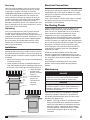
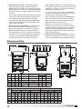
Installation
Follow the steps shown below. Attach the plenum and
hood to the roof curb using a suitable fastener in each of
the prepunched mounting holes. Care must be taken not
to bend or distort the plenum and fan components during
installation.
1. Mount and secure the roof curb over the roof opening
to the roof structurals.
2. Lower the plenum (factory assembled) through the
curb and roof opening until its mounting channels rest
on the roof curb. Lifting Lugs are provided. (Figure 1)
3. Lower the hood
onto the curb/
plenum assembly.
(Figure 1)
4. The hood and
plenum are
secured to the
roof curb.
(Figure 2)
Electrical Connections
Before electrical connections are made, the supply
voltage, phase and ampere capacity must be checked for
compatibility with the fan motor. In addition, the supply
wiring must be properly fused and conform to local and
national electrical codes.
If fan is to be wired to a control center, which is available
through the manufacturer, the control center wiring
instructions must be followed.
Pre-Starting Checks
Check all fasteners and set screws for tightness. The
propeller should rotate freely and not rub on the fan
panel. The unit was aligned and test run at the factory
prior to shipment, however movement of various
components may occur during shipment. Proper
propeller rotation should be determined by momentarily
energizing the fan in the exhaust mode. If the rotation in
the exhaust mode is for supply the motor wiring between
the fan and the controls should be changed. For 3-phase
installations, fan rotation can be reversed by simply
interchanging any two of the three electrical leads. For
single-phase installations, follow the wiring diagram
located on the motor.
Guards are required to protect the fan and nearby
personnel. If guards are not ordered with the fan, they
must be supplied by the installer. When ordered with the
fan, the guard is attached to the bottom of the double
venturi panel.
Plenum dampers should open to 45° from closed
position. Consult factory before adjusting damper
linkages.
Once the fan has been put into operation, a periodic
maintenance program should be set up to preserve
the reliability and performance of the fan. Items to be
included in this program are:
1. Motors - Greasing of motors is intended only when
fittings are provided. Many fractional horsepower
motors are lubricated for life and require no further
lubrication. Motors supplied with grease fittings
should be greased in accordance with the motor
manufacturer’s directions given on the motor
nameplate.
Hood
Mounting
Channels
Lifting
Lugs
Roof
Curb
Plenum
Figure 1
Figure 2
Figure 1
Hood
Mounting
Channels
Lifting
Lugs
Roof
Curb
Plenum
Figure 1
Figure 2
Figure 2
DANGER
Always disconnect, lock and tag power source before
installing or servicing. Failure to disconnect power
source can result in fire, shock or serious injury.
DANGER
Pour écarter les risques d’incendie, de choc électrique
ou de blessure grave, veiller à toujours débrancher,
verrouiller et étiqueter la source de courant avant
l’installation ou l’entretien.
Maintenance
Four Way Fans2
®

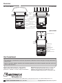
Dimensional Data
Control Damper
Low Leakage Control Damper
OPTIONAL DIFFUSER
H
OPTIONAL DIFFUSER
12 in.
C
G
A Sq.
B Sq.
Roof Opening
*
20 in.
E
D
ACCESS DOOR
F
5 in.
*
Option: Plenum height can be increased in
12 inch increments.
See page 4 of Four Way catalog.
Low Leakage Control Damper
Control Damper
Control Damper
OPTIONAL DIFFUSER
H
F
C
A Sq.
B Sq.
Roof Opening
*
20 in.
5 in.
*
Option: Plenum height can be increased in 12 inch increments
See page 4 of Four Way catalog.
G
D x E
Access
Door
Non-Filtered Model
Upblast Model
Model
Size
A B C*
Top Damper
VCD-2120
Recirculation Damper
VCD-1020 (W x H)
Access Doors
Roof
Opening
D E
24 40 32 58
1
⁄2 29 x 29 27 x 26 21 20 34
1
⁄2
30 46 38 63 35 x 35 33 x 30 27 20 40
1
⁄2
36 52 44 71
5
⁄8 41 x 41 39 x 38 33 22 46
1
⁄2
42 58 50 75
3
⁄4 47 x 47 44 x 42 38 36 52
1
⁄2
48 64 56 82
5
⁄8 53 x 53 50 x 48 44 36 58
1
⁄2
54 70 62 91 59 x 59 56 x 54 50 36 64
1
⁄2
All dimensions shown are in inches.
Model
Size
Sizes Approximate Unit Weights (LBS.)
Non-Filtered Hood Filtered Hood Upblast Hood Non-Filtered Filtered Hood Upblast Hood
F G H F G H F G H Alum Galv Alum Galv Alum Galv
24 63 66 30 63 66 30 2
1
⁄4 31
3
⁄8 26
1
⁄4 570 650 670 750 400 480
30 75 74 32 75 78 32 3
1
⁄2 37
3
⁄8 30
3
⁄8 760 900 860 1000 490 630
36 87 76 33 87 94 33 4
1
⁄2 43
3
⁄4 33
3
⁄4 1040 1200 1170 1330 715 875
42 99 86 36
1
⁄2 99 100 36
1
⁄2 4
1
⁄2 50 38
1
⁄2 1200 1400 1330 1530 850 1050
48 111 100 36
1
⁄2 111 112 36
1
⁄2 5
1
⁄2 56
1
⁄4 41 1470 1700 1620 1850 1110 1340
54 111 112 39 112 124 39 5
1
⁄2 63
3
⁄8 45 1770 2000 1920 2150 1405 1635
All dimensions shown are in inches.
2. Removal of Dust and Dirt - Non-filtered models
require periodic cleaning to maintain proper air
performance and reliability. Dirt left to accumulate on
propeller blades may cause an unbalanced condition
resulting in excessive vibration and premature failure
of the fan.
Dust and dirt should also be cleaned from the exterior
surface of the fan motor and damper actuator(s). Dirt
accumulation on the motor/actuator(s) can block
ventilation holes and prevent proper cooling. Motors
and actuators should never be sprayed directly with
water, steam or solvents.
3. Maintenance for Filtered Models - Aluminum mesh
filters should be cleaned on a regular basis for
optimum fan efficiency. The frequency of cleaning
depends upon the cleanliness of the incoming air.
To remove filters in fan sizes 24 and 30, first remove
the hood. This is accomplished by removing the two
fasteners on one side of the hood and loosening
the other two fasteners on the other side of the
hood. Hinge the hood over onto the roof deck; DO
NOT prop the hood up, the hood could come down
accidentally causing injury. The filters can then be
pulled from the slide-out racks.
On sizes 36 to 54, access panels are provided in
the ends of the hood which allow the filters to be
removed without removing the hood.
Filters should be washed with a mild detergent in
warm water. After the filters are dry, an adhesive
spray available at most filter distributors may be
applied to increase filter efficiency.
4. Fasteners - Fan vibration has a tendency to
loosen mechanical fasteners. Periodic inspection
should include checking all fasteners for tightness.
Particular attention should be paid to fasteners
attaching the propeller to the motor shaft and the
motor to the motor plate.
5. Damper Plenum Linkage Adjustments - Plenum
dampers should open to 45
o
from closed position.
Consult factory before adjusting damper linkages.
Filtered Model
Four Way Fans 3
®

Parts List
Control Damper
OPTIONAL DIFFUSER
Butterfly Dampers (2)
VCD-1020 (2)
Fan Motor
Damper Actuator
Motor Plate
Drive Frame Angle (2)
Propeller
Double Venturi Panel
OPTIONAL DIFFUSER
ACCESS DOOR
Birdscreen
or
Filters
VCD-2120
Fan Motor
Damper Actuator
Motor Plate
Drive Frame Angle (2)
Propeller
Double Venturi Panel
VCD-1020 (2)
Low Leakage Control Damper Low Leakage Control Damper
OPTIONAL DIFFUSER
Control Damper
Control Damper
Non-Filtered Model
Filtered Model
Upblast Model
453668 • ERD/ESRMD/ESRMDF, Rev. 3, June 2018 Copyright 2018 © Greenheck Fan Corporation4
As a result of our commitment to continuous improvement, Greenheck reserves the right to change specifications
without notice.
Specific Greenheck product warranties are located on greenheck.com within the product area tabs and in the
Library under Warranties.
Greenheck Recirculating Roof Fans catalog provides
additional information describing the equipment, fan
performance, available accessories, and specification data.
®
Phone: 715.359.6171 • Fax: 715.355.2399 • Parts: 800.355.5354 • E-mail: [email protected] • Website: www.greenheck.com
Our Commitment
AMCA Publication 410-96, Safety Practices for Users and
Installers of Industrial and Commercial Fans, provides
additional safety information. This publication can be
obtained from AMCA International, Inc. at www.amca.org.
-
 1
1
-
 2
2
-
 3
3
-
 4
4


Greenheck 453668 ESRMD/ERD Mode d'emploi
- Taper
- Mode d'emploi
dans d''autres langues
Documents connexes
-
Greenheck 453905 TAUD/TAUB Mode d'emploi
-
-
-
-
-
-
Autres documents
-
Trane Horizon OANE360A Installation, Operation and Maintenance Manual
-
-
Miller FILTAIR INDUSTRIAL COLLECTOR SERIES Le manuel du propriétaire
-
Miller FILTAIR INDUSTRIAL COLLECTOR SERIES (460 VOLT) Le manuel du propriétaire
-
-
-
ClimateMaster Dedicated Outside Air Systems Le manuel du propriétaire