MINN KOTA MINN-KOTA 1363885 EO Transom Mount Electric Outboard Motor Manuel utilisateur
- Taper
- Manuel utilisateur

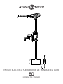
EO
TRANSOM-MOUNT ELECTRIC OUTBOARD MOTOR
USER MANUAL

Model: _________________________________________________________________________________________________________________________
Serial Number: _______________________________________________________________________________________________________________
Purchase Date: _______________________________________________________________________________________________________________
Store Where Purchased: ____________________________________________________________________________________________________
NOTE: Do not return your Minn Kota motor to your retailer. Your retailer is not authorized to repair or replace this unit. You may obtain service
by: calling Minn Kota at (800) 227-6433; returning your motor to the Minn Kota Factory Service Center; sending or taking your motor to any
Minn Kota authorized service center. A list of authorized service centers is available on our website, at minnkotamotors.com. Please include proof of
purchase, serial number and purchase date for warranty service with any of the above options.
Please thoroughly read this user manual. Follow all instructions and heed all safety and cautionary notices below. Use of this motor is only
permitted for persons that have read and understood these user instructions. Minors may use this motor only under adult supervision.
ATTENTION: Never run the motor out of the water, as this may result in injuries from the rotating propeller. The motor should be disconnected from
the power source when it is not in use or is off the water. When connecting the power-supply cables of the motor to the battery, ensure that they are
not kinked or subject to chafe and route them in such a way that persons cannot trip over them. Before using the motor make sure that the insulation
of the power cables is not damaged. Disregarding these safety precautions may result in electric shorts of battery(s) and/or motor. Always disconnect
motor from battery(s) before cleaning or checking the propeller. Avoid submerging the complete motor as water may enter the lower unit through
control head and shaft. If the motor is used while water is present in the lower unit considerable damage to the motor can occur. This damage will not
be covered by warranty.
CAUTION: Take care that neither you nor other persons approach the turning propeller too closely, neither with body parts nor with objects. The
motor is powerful and may endanger or injure you or others. While the motor is running watch out for persons swimming and for fl oating objects.
Persons whose ability to run the motor or whose reactions are impaired by alcohol, drugs, medication, or other substances are not permitted to use
this motor. This motor is not suitable for use in strong currents. The constant noise pressure level of the motor during use is less than 70dB(A). The
overall vibration level does not exceed 2,5m/sec2.
THANK YOU
Thank you for choosing Minn Kota. We believe that you should spend more time fi shing and less time positioning your
boat. That’s why we build the smartest, toughest, most intuitive motors on the water. Every aspect of a Minn Kota motor is
thought out and rethought until it’s good enough to bear our name. Countless hours of research and testing provide you the
Minn Kota advantage that can truly take you “Anywhere. Anytime.” We don’t believe in shortcuts. We are Minn Kota. And we are
never done helping you catch more fi sh.
REMEMBER TO KEEP YOUR RECEIPT AND IMMEDIATELY REGISTER YOUR MOTOR.
A registration card is enclosed or you can complete registration on our website at minnkotamotors.com.
LOCATING YOUR SERIAL NUMBER
Your Minn Kota 11-character serial number is very important. It helps to determine the specifi c model and year of manufacture. When contacting
Consumer Service or registering your product, you will need to know your product’s serial number. We recommend that you write the serial number
down in the space provided below so that you have it available for future reference.
CE MASTER USER MANUAL (FOR CE/C-TICK CERTIFIED MODELS)
Conforms to 89/336/EEC (EMC) under standards EN 55022A, EN 50082-2 since 1996 LN V9677264
2 | minnkotamotors.com ©2015 Johnson Outdoors Marine Electronics, Inc.
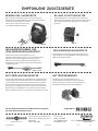
The serial number on your EO is located under
the tiller handle.
Made by Minn Kota
Johnson Outdoors
Marine Electronics, Inc.
121 Power Drive
Mankato, MN 56001 USA
Outboard Motors
Produced in 2015
EO - 1/2 HP
MODEL 1363880
SER NO M365 MK12345
EXAMPLE

minnkotamotors.com | 3
©2015 Johnson Outdoors Marine Electronics, Inc.
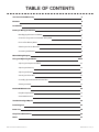
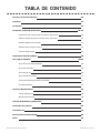
TABLE OF CONTENTS
Two-Year Limited Warranty 4
Features 5
Installation 6
Battery & Wiring Installation 7-8
Boat Rigging & Product Installation 7
Conductor Gauge and Circuit Breaker Sizing Table 7
Push-to-Test Battery Meter 7
Selecting the Correct Batteries 8
Connecting the Batteries 8
Motor Wiring Diagram 9
Using and Adjusting the Motor 10-11
Adjusting the Depth of the Motor 10
Adjusting the Steering 10
Adjusting the Bracket 11
Adusting the Twist Tiller 11
Controlling Speed & Direction with the Tiller 10
Stowing the Motor 11
Service & Maintenance 12
Propeller Replacement 12
General Maintenance 12
Troubleshooting & Repair 13
Parts Diagram 14
Parts List 15
Compliance Statements 16
Notes 17

WARRANTY ON MINN KOTA EO ELECTRIC OUTBOARD MOTORS
Johnson Outdoors Marine Electronics, Inc. (“JOME”) extends the following limited warranty to the original retail purchaser only. Warranty coverage is not
transferable.
MINN KOTA LIMITED TWO-YEAR WARRANTY ON THE ENTIRE PRODUCT
JOME warrants to the original retail purchaser only that the purchaser’s new Minn Kota primary propulsion motor will be materially free from defects in materials
and workmanship appearing within two (2) years after the date of purchase. JOME will (at its option) either repair or replace, free of charge, any parts found by
JOME to be defective during the term of this warranty. Such repair, or replacement shall be the sole and exclusive liability of JOME and the sole and exclusive
remedy of the purchaser for breach of this warranty.
MINN KOTA LIMITED LIFETIME WARRANTY ON COMPOSITE SHAFT
JOME warrants to the original retail purchaser only that the composite shaft of the purchaser’s Minn Kota motor will be materially free from defects in materials
and workmanship appearing within the original purchaser’s lifetime. JOME will provide a new composite shaft, free of charge, to replace any composite shaft
found by JOME to be defective during the term of this warranty. Providing a new composite shaft shall be the sole and exclusive liability of JOME and the
sole and exclusive remedy of the purchaser for breach of this warranty; and purchaser shall be responsible for installing, or for the cost of labor to
install, any new composite shaft provided by JOME.
EXCLUSIONS & LIMITATIONS
This limited warranty does not apply to products that have been used commercially or for rental purposes. This limited warranty does not cover normal wear
and tear, blemishes that do not aff ect the operation of the product, or damage caused by accidents, abuse, alteration, modifi cation, shipping damages, acts
of God, negligence of the user or misuse, improper or insuffi cient care or maintenance. DAMAGE CAUSED BY THE USE OF OTHER REPLACEMENT
PARTS NOT MEETING THE DESIGN SPECIFICATIONS OF THE ORIGINAL PARTS WILL NOT BE COVERED BY THIS LIMITED WARRANTY.
The cost of normal maintenance or replacement parts which are not in breach of the limited warranty are the responsibility of the purchaser. Prior to using
products, the purchaser shall determine the suitability of the products for the intended use and assumes all related risk and liability. Any assistance JOME
provides to or procures for the purchaser outside the terms, limitations or exclusions of this limited warranty will not constitute a waiver of the terms, limitations
or exclusions, nor will such assistance extend or revive the warranty. JOME will not reimburse the purchaser for any expenses incurred by the purchaser
in repairing, correcting or replacing any defective products or parts, except those incurred with JOME’s prior written permission. JOME’S AGGREGATE
LIABILITY WITH RESPECT TO COVERED PRODUCTS IS LIMITED TO AN AMOUNT EQUAL TO THE PURCHASER’S ORIGINAL PURCHASE
PRICE PAID FOR SUCH PRODUCT.
MINN KOTA SERVICE INFORMATION
To obtain warranty service in the U.S., the product believed to be defective, and proof of original purchase (including the date of purchase), must be presented
to a Minn Kota Authorized Service Center or to Minn Kota’s factory service center in Mankato, MN. Any charges incurred for service calls, transportation or
shipping/freight to/from the Minn Kota Authorized Service Center or factory, labor to haul out, remove, re-install or re-rig products removed for warranty service,
or any other similar items are the sole and exclusive responsibility of the purchaser. Products purchased outside of the U.S. must be returned prepaid with
proof of purchase (including the date of purchase and serial number) to any Authorized Minn Kota Service Center in the country of purchase. Warranty service
can be arranged by contacting a Minn Kota Authorized Service Center or by contacting the factory at 1-800-227-6433 or email service@minnkotamotors.com.
Products repaired or replaced will be warranted for the remainder of the original warranty period [or for 90 days from the date of repair
or replacement, whichever is longer]. For any product that is returned for warranty service that JOME fi nds to be not covered by or not
in breach of this limited warranty, there will be a billing for services rendered at the prevailing posted labor rate and for a minimum of at
least one hour.
NOTE: Do not return your Minn Kota product to your retailer. Your retailer is not authorized to repair or replace products.
THERE ARE NO EXPRESS WARRANTIES OTHER THAN THESE LIMITED WARRANTIES. IN NO EVENT SHALL ANY IMPLIED
WARRANTIES INCLUDING ANY IMPLIED WARRANTIES OF MERCHANTABILITY OR FITNESS FOR PARTICULAR PURPOSE, EXTEND
BEYOND THE DURATION OF THE RELEVANT EXPRESS LIMITED WARRANTY. IN NO EVENT SHALL JOME BE LIABLE FOR PUNITIVE,
INDIRECT, INCIDENTAL, CONSEQUENTIAL OR SPECIAL DAMAGES. Without limiting the foregoing, JOME assumes no responsibility for
loss of use of product, loss of time, inconvenience or other damage.
Some states do not allow limitations on how long an implied warranty lasts or the exclusion or limitation of incidental or consequential damages, so the above
limitations and/or exclusions may not apply to you. This warranty gives you specifi c legal rights and you may also have other legal rights which vary from state
to state.
4 | minnkotamotors.com ©2015 Johnson Outdoors Marine Electronics, Inc.
TWO-YEAR LIMITED WARRANTY

WARRANTY ON MINN KOTA EO ELECTRIC OUTBOARD MOTORS
Johnson Outdoors Marine Electronics, Inc. (“JOME”) extends the following limited warranty to the original retail purchaser only. Warranty coverage is not
transferable.
MINN KOTA LIMITED TWO-YEAR WARRANTY ON THE ENTIRE PRODUCT
JOME warrants to the original retail purchaser only that the purchaser’s new Minn Kota primary propulsion motor will be materially free from defects in materials
and workmanship appearing within two (2) years after the date of purchase. JOME will (at its option) either repair or replace, free of charge, any parts found by
JOME to be defective during the term of this warranty. Such repair, or replacement shall be the sole and exclusive liability of JOME and the sole and exclusive
remedy of the purchaser for breach of this warranty.
MINN KOTA LIMITED LIFETIME WARRANTY ON COMPOSITE SHAFT
JOME warrants to the original retail purchaser only that the composite shaft of the purchaser’s Minn Kota motor will be materially free from defects in materials
and workmanship appearing within the original purchaser’s lifetime. JOME will provide a new composite shaft, free of charge, to replace any composite shaft
found by JOME to be defective during the term of this warranty. Providing a new composite shaft shall be the sole and exclusive liability of JOME and the
sole and exclusive remedy of the purchaser for breach of this warranty; and purchaser shall be responsible for installing, or for the cost of labor to
install, any new composite shaft provided by JOME.
EXCLUSIONS & LIMITATIONS
This limited warranty does not apply to products that have been used commercially or for rental purposes. This limited warranty does not cover normal wear
and tear, blemishes that do not aff ect the operation of the product, or damage caused by accidents, abuse, alteration, modifi cation, shipping damages, acts
of God, negligence of the user or misuse, improper or insuffi cient care or maintenance. DAMAGE CAUSED BY THE USE OF OTHER REPLACEMENT
PARTS NOT MEETING THE DESIGN SPECIFICATIONS OF THE ORIGINAL PARTS WILL NOT BE COVERED BY THIS LIMITED WARRANTY.
The cost of normal maintenance or replacement parts which are not in breach of the limited warranty are the responsibility of the purchaser. Prior to using
products, the purchaser shall determine the suitability of the products for the intended use and assumes all related risk and liability. Any assistance JOME
provides to or procures for the purchaser outside the terms, limitations or exclusions of this limited warranty will not constitute a waiver of the terms, limitations
or exclusions, nor will such assistance extend or revive the warranty. JOME will not reimburse the purchaser for any expenses incurred by the purchaser
in repairing, correcting or replacing any defective products or parts, except those incurred with JOME’s prior written permission. JOME’S AGGREGATE
LIABILITY WITH RESPECT TO COVERED PRODUCTS IS LIMITED TO AN AMOUNT EQUAL TO THE PURCHASER’S ORIGINAL PURCHASE
PRICE PAID FOR SUCH PRODUCT.
MINN KOTA SERVICE INFORMATION
To obtain warranty service in the U.S., the product believed to be defective, and proof of original purchase (including the date of purchase), must be presented
to a Minn Kota Authorized Service Center or to Minn Kota’s factory service center in Mankato, MN. Any charges incurred for service calls, transportation or
shipping/freight to/from the Minn Kota Authorized Service Center or factory, labor to haul out, remove, re-install or re-rig products removed for warranty service,
or any other similar items are the sole and exclusive responsibility of the purchaser. Products purchased outside of the U.S. must be returned prepaid with
proof of purchase (including the date of purchase and serial number) to any Authorized Minn Kota Service Center in the country of purchase. Warranty service
can be arranged by contacting a Minn Kota Authorized Service Center or by contacting the factory at 1-800-227-6433 or email service@minnkotamotors.com.
Products repaired or replaced will be warranted for the remainder of the original warranty period [or for 90 days from the date of repair
or replacement, whichever is longer]. For any product that is returned for warranty service that JOME fi nds to be not covered by or not
in breach of this limited warranty, there will be a billing for services rendered at the prevailing posted labor rate and for a minimum of at
least one hour.
NOTE: Do not return your Minn Kota product to your retailer. Your retailer is not authorized to repair or replace products.
THERE ARE NO EXPRESS WARRANTIES OTHER THAN THESE LIMITED WARRANTIES. IN NO EVENT SHALL ANY IMPLIED
WARRANTIES INCLUDING ANY IMPLIED WARRANTIES OF MERCHANTABILITY OR FITNESS FOR PARTICULAR PURPOSE, EXTEND
BEYOND THE DURATION OF THE RELEVANT EXPRESS LIMITED WARRANTY. IN NO EVENT SHALL JOME BE LIABLE FOR PUNITIVE,
INDIRECT, INCIDENTAL, CONSEQUENTIAL OR SPECIAL DAMAGES. Without limiting the foregoing, JOME assumes no responsibility for
loss of use of product, loss of time, inconvenience or other damage.
Some states do not allow limitations on how long an implied warranty lasts or the exclusion or limitation of incidental or consequential damages, so the above
limitations and/or exclusions may not apply to you. This warranty gives you specifi c legal rights and you may also have other legal rights which vary from state
to state.
Steering Tension Knob
minnkotamotors.com | 5
©2015 Johnson Outdoors Marine Electronics, Inc.
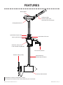
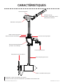
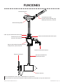
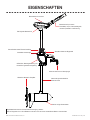
FEATURES
Specifications subject to change without notice.
This diagram is for reference only and may differ from your actual motor.
Battery Meter
Weedless Wedge 2 Prop
Tilt/Extend Tiller
Controls: on/off, speed,
forward/reverse and direction
Quick Release Depth Collar
Quick Release Tilt Lever
Transom Clamp Screws
9-Position, Heavy-Duty
Lever Lock Mounting Bracket
Lifetime Warranty
Flexible Composite Shaft
Cool Quiet Power Motor
EO Digital Maximizer™

6 | minnkotamotors.com ©2015 Johnson Outdoors Marine Electronics, Inc.
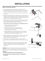
INSTALLATION
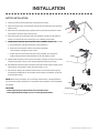
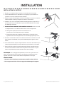
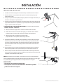
HANDLE INSTALLATION
1. Remove the wire clip from the ball detent located on the inner handle.
2. Install outer handle over inner handle. Position the handles so the ball detent and OFF are aligned.
3. Push the outer handle into the control box until handle “clicks” into place. The handle is held in place with locking fi ngers, so
some force may be required to lock the handles together.
4. Once the handle is locked into the control box, it can be rotated and extended for normal use.
5. Once the handle is installed, the assembly is permanent. Do not attempt to remove the handle.
MOTOR INSTALLATION
1. Find a transom area of the boat that is free from obstructions.
2. Open the clamp screws on the bracket enough so that it will fi t over the top of the
boat transom.
3. Place the Lever Lock Mounting bracket over the top of the boat transom so that
the bracket is resting on top of the transom.
4. Verify that there are no obstacles that the control box, handle, or prop might hit
while in use that would restrict steering or cause damage to the motor.
5. Tighten down the clamp screws to the transom by hand only. Do not use any tools
to tighten the clamp screws as this may damage the bracket or your boat.
6. We recommend the tilt angle of the motor to be adjusted so that the motor shaft is
perpendicular to the water surface when the motor is in use.
7. For transport, always tilt the motor into the boat, such that the motor and prop
assembly are completely out of the water and the motor is positioned up close to
the lever lock bracket.
NOTE: When setting the depth, be sure the top of the motor is submerged at least
12” to avoid churning or agitation of surface water. The propeller must be completely
submerged.
CAUTION:
• Never operate your motor when it is out of the water.
• Over-tightening the clamp screws can damage the bracket.
Inner Handle
Detent/Wire Clip
Outer Handle
O ff
Ball Detent
HANDLE INSTALLATION
1. Remove the wire clip from the ball detent located on the inner handle.
2. Install outer handle over inner handle. Position the handles so the ball detent and OFF are aligned.
3. Push the outer handle into the control box until handle “clicks” into place. The handle is held in place with locking fi ngers, so
some force may be required to lock the handles together.
4. Once the handle is locked into the control box, it can be rotated and extended for normal use.
5. Once the handle is installed, the assembly is permanent. Do not attempt to remove the handle.
MOTOR INSTALLATION
1. Find a transom area of the boat that is free from obstructions.
2. Open the clamp screws on the bracket enough so that it will fi t over the top of the
boat transom.
3. Place the Lever Lock Mounting bracket over the top of the boat transom so that
the bracket is resting on top of the transom.
4. Verify that there are no obstacles that the control box, handle, or prop might hit
while in use that would restrict steering or cause damage to the motor.
5. Tighten down the clamp screws to the transom by hand only. Do not use any tools
to tighten the clamp screws as this may damage the bracket or your boat.
6.
We recommend the tilt angle of the motor to be adjusted so that the motor shaft is
perpendicular to the water surface when the motor is in use.
7. For transport, always tilt the motor into the boat, such that the motor and prop
assembly are completely out of the water and the motor is positioned up close to
the lever lock bracket.
NOTE: When setting the depth, be sure the top of the motor is submerged at least
12” to avoid churning or agitation of surface water. The propeller must be completely
submerged.
CAUTION:
• Never operate your motor when it is out of the water.
• Over-tightening the clamp screws can damage the bracket.
Inner Handle
Detent/Wire Clip
Outer Handle
O ff
Ball Detent
2 | minnkotamotors.com ©2013 Johnson Outdoors Marine Electronics, Inc.
TRANSOM EXTRUSION INSTALLATION (PART NUMBER 2994844)
a. Set the motor on transom with clamp screws backed out.
b. Slide extrusion between inside of transom and the clamp
screw washers and tighten clamp screws.
c. Attach extrusion to transom with two screws provided. This will require
drilling two appropriate sized pilot holes for the self tapping screws.
Extrusion

BOAT RIGGING & PRODUCT INSTALLATION
For safety and compliance reasons, we recommend that you follow American Boat and Yacht Council (ABYC) standards when
rigging your boat. Altering boat wiring should be completed by a qualifi ed marine technician. The following specifi cations are for
general guidelines only:
CAUTION: These guidelines apply to general rigging to support your Minn Kota motor. Powering multiple motors or additional
electrical devices from the same power circuit may impact the recommended conductor gauge and circuit breaker size. If you are
using wire longer than that provided with your unit, follow the conductor gauge and circuit breaker sizing table below. If your wire
extension length is more than 25 feet, we recommend that you contact a qualifi ed marine technician.
An over-current protection device (circuit breaker or fuse) must be used. Coast Guard requirements dictate that
each ungrounded current-carrying conductor must be protected by a manually reset, trip-free circuit breaker or fuse. The type
(voltage and current rating) of the fuse or circuit breaker must be sized accordingly to the trolling motor used. The table below gives
recommended guidelines for circuit breaker sizing.
Reference:
United States Code of Federal Regulations: 33 CFR 183 – Boats and Associated Equipment
ABYC E-11: AC and DC Electrical Systems on Boats
CONDUCTOR GAUGE AND CIRCUIT BREAKER SIZING TABLE
Motor Thrust /
Model Max Amp Draw Circuit Breaker Wire Extension Length *
5 feet 10 feet 15 feet 20 feet 25 feet
30 lb. 30 50 Amp @ 12 VDC 10 AWG 10 AWG 8 AWG 6 AWG 4 AWG
40 lb., 45 lb. 42 10 AWG 8 AWG 6 AWG 4 AWG 4 AWG
50 lb., 55 lb. 50 60 Amp @ 12 VDC 8 AWG 6 AWG 4 AWG 4 AWG 2 AWG
70 lb. 42 50 Amp @ 24 VDC 10 AWG 10 AWG 8 AWG 8 AWG 6 AWG
80 lb. 56 60 Amp @ 24 VDC 8 AWG 8 AWG 8 AWG 6 AWG 6 AWG
101 lb. 46 50 Amp @ 36 VDC 8 AWG 8 AWG 8 AWG 8 AWG 8 AWG
Engine Mount 101 50 60 Amp @ 36 VDC 8 AWG 6 AWG 4 AWG 4 AWG 2 AWG
112 lb. 52 60 Amp @ 36 VDC 8 AWG 8 AWG 8 AWG 8 AWG 8 AWG
Engine Mount 160 116 (2) x 60 Amp @ 24 VDC 2 AWG 2 AWG 2 AWG 2 AWG 2 AWG
E-Drive 40 50 Amp @ 48 VDC 10 AWG 10 AWG 10 AWG 10 AWG 10 AWG
This conductor and circuit breaker sizing table is only valid for the following assumptions:
1. No more than 3 conductors are bundled together inside of a sheath or conduit outside of engine spaces.
2. Each conductor has 105° C temp rated insulation.
3. No more than 5% voltage drop allowed at full motor power based on published product power requirements.
*Wire Extension Length refers to the distance from the batteries to the trolling motor leads.
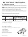
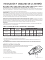
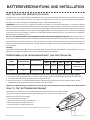
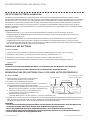
PUSH-TO-TEST BATTERY METER
This motor is equipped with a “push-to-test” battery meter. The LED light provides an accurate
display of the remaining charge in the battery. It is only accurate when the motor is off .
The meter reads as:
• One light indicates recharge.
• Two lights indicate low charge.
• Three lights indicate good charge.
• Four lights indicate full charge.
minnkotamotors.com | 7
©2015 Johnson Outdoors Marine Electronics, Inc.
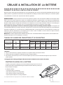
BATTERY WIRING & INSTALLATION
Motor Thrust /
Model Max Amp Draw Circuit Breaker Wire Extension Length *
5 feet 10 feet 15 feet 20 feet 25 feet
EO 1/2 HP 52 60 Amp @ 12 VDC 6 AWG 2 AWG 1 AWG 1/0 AWG NOT
RECOMMENDED
EO 1 HP 45 50 Amp @ 24 VDC 8 AWG 6 AWG 4 AWG 2 AWG 2 AWG
This conductor and circuit breaker sizing table is only valid for the following assumptions:
1. No more than 3 conductors are bundled together inside of a sheath or conduit outside of engine spaces.
2. Each conductor has 105° C temp rated insulation.
3. No more than 27% voltage drop allowed at full motor power based on published product power requirements.
*Wire Extension Length refers to the distance from the batteries to the motor leads.
*Battery meter will not be accurate when using lithium batteries.
*
2 | minnkotamotors.com ©2013 Johnson Outdoors Marine Electronics, Inc.
TRANSOM EXTRUSION INSTALLATION (PART NUMBER 2994844)
a. Set the motor on transom with clamp screws backed out.
b. Slide extrusion between inside of transom and the clamp
screw washers and tighten clamp screws.
c. Attach extrusion to transom with two screws provided. This will require
drilling two appropriate sized pilot holes for the self tapping screws.

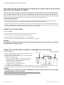
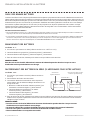
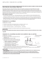
CONNECTING THE BATTERIES IN SERIES (IF REQUIRED FOR YOUR MOTOR)
24 VOLT SYSTEMS:
1. Make sure that the motor is switched off (speed selector on “0”).
2. Two 12 volt batteries are required.
3. The batteries must be wired in series, only as directed in wiring
diagram, to provide 24 volts.
a. Connect a connector cable to the positive ( + ) terminal of
battery 1 and to the negative ( – ) terminal of battery 2.
b. Connect positive ( + ) red motor lead to
positive ( + ) terminal on battery 2.
c. Connect negative ( – ) black motor lead to
negative ( – ) terminal of battery 1.
4. For safety reasons do not switch the motor on until the propeller is in the water. If installing a leadwire plug, observe proper
polarity and follow instructions in your boat owner’s manual. See wiring diagram on following pages.
CAUTION
• For safety reasons, disconnect the motor from the battery or batteries when the motor is not in use or while
the battery/batteries are being charged.
• Improper wiring of 24/36 volt systems could cause battery explosion!
• Keep leadwire wing nut connections tight and solid to battery terminals.
• Locate battery in a ventilated compartment.
To trolling motor negative
24 Volt Series Connection
Battery #1 (Low Side)
Neg - Neg -Pos + Pos +
Battery #2 (High Side)
+24 Volts to trolling motor
positive (or circuit breaker)
Two 12-volt batteries connected in series for 24 volts
SELECTING THE CORRECT BATTERIES
The motor will operate with any lead acid, deep cycle marine or lithium 12 volt battery/batteries. Maintain lead acid batteries at
full charge. Lithium batteries should be stored at less than full charge and only need to be fully charged before use. Proper care
will ensure having battery power when you need it, and will significantly improve the battery life. Failure to recharge lead-acid
batteries (within 12-24 hours) is the leading cause of premature battery failure. We offer a wide selection of lead-acid chargers to
fit your charging needs. We recommend that you use separate batteries for your Minn Kota EO motor.
Advice Regarding Batteries:
• Never connect the (+) and the (–) terminals of the same battery together. Take care that no metal object can fall onto the
battery and short the terminals. This would immediately lead to a short and extreme fire danger.
• It is highly recommended that a circuit breaker or fuse be used with this trolling motor. Refer to “Conductor Gauge and Circuit
Breaker Sizing Table” in the previous section to find the appropriate circuit breaker or fuse for your motor. For motors requiring
a 60-amp breaker, the Minn Kota MKR-19 60-amp circuit breaker is recommended.
CONNECTING THE BATTERIES
12 VOLT SYSTEMS:
1. Make sure that the motor is switched off (speed selector on “OFF” or “0”).
2. Connect positive ( + ) red lead to positive ( + ) battery terminal.
3. Connect negative ( – ) black lead to negative ( – ) battery terminal.
4. For safety reasons do not switch the motor on until the propeller is in the water.
CAUTION:
For safety reasons, disconnect the motor from the battery/batteries when the motor is not in use or while the
battery/batteries are being charged.
8 | minnkotamotors.com ©2015 Johnson Outdoors Marine Electronics, Inc.
BATTERY WIRING & INSTALLATION
To motor negative
24 Volt Connection
Battery #1 (Low Side)
Neg - Neg -Pos + Pos +
Battery #2 (High Side)
+24 Volts to motor positive
(or circuit breaker)
24 Volt Series Connection

minnkotamotors.com | 9
©2015 Johnson Outdoors Marine Electronics, Inc.
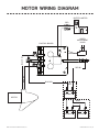
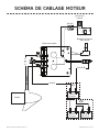
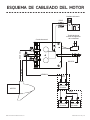
MOTOR WIRING DIAGRAM
12v
24v
MOTOR
SPEED
ADJUSTMENT
KNOB
BATTERY METER
CONTROL BOARD
RED
12V BATT 1
12V BATT 1 12V BATT 2
BLACK
RED M+ BLACK M-
BLACK B-
RED B+

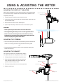
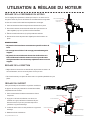
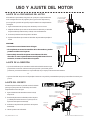
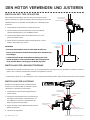
ADJUSTING THE DEPTH OF THE MOTOR
When setting the depth be sure the top of the motor is submerged at least
12” to avoid churning or agitation of surface water. The propeller must be
completely submerged.
1. Firmly grasp the composite shaft and hold it steady.
2. Loosen the steering tension knob and adjustable depth collar knob until
the shaft slides freely.
3. Raise or lower the motor to the desired depth.
4. Tighten adjustable depth collar knob to secure the motor in place.
CAUTION:
• Never operate your motor when it is out of the water.
• Over-tightening the clamp screws can damage the bracket.
• Never loosen the steering tension knob without securely
holding the shaft of the motor. Failing to do so will cause the
motor to rapidly fall against the bracket.
ADJUSTING THE STEERING
• Adjust the steering tension knob to provide enough tension to allow the
motor to turn freely, yet remain in any position without being held
OR
• Tighten the knob to place the motor in a preset position to leave your
hands free for fi shing.
Adjustable Depth Collar Knob
Steering Tension Knob
12” Minimum
Depth
Steering Tension Knob
Transom Clamp Screws
Quick Release Depth Collar
Tilt Lock Lever
Mounting Bracket
Steering Tension Knob
Quick-Release Depth Collar
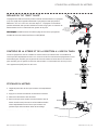
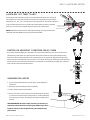
ADJUSTING THE BRACKET
You can lock your motor in a vertical position, angle it
for shallow water or tilt it completely out of the water.
1. Firmly grasp the control head or composite shaft.
2. Press the tilt lever down towards the bracket the
shaft and hold to release the T-bar to adjust the
position of the mounting bracket.
3. Tilt to any of the positions on the mounting bracket.
4. Release the tilt lever.
10 | minnkotamotors.com ©2015 Johnson Outdoors Marine Electronics, Inc.
USING & ADJUSTING THE MOTOR
12” Minimum
Depth

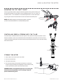
CONTROLLING SPEED & STEERING WITH THE TILLER
This motor off ers variable forward and reverse speeds. The speed control may be operated in either
direction, forward or reverse. Turn the tiller handle counterclockwise from (OFF) to increase reverse
speed and clockwise from (OFF) to increase forward speed. Speed decreases as you approach (OFF)
from either direction.
Forward
Reverse
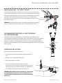
ADJUSTING THE BRACKET
You can lock your motor in a vertical position, angle it for shallow water or tilt it completely out of the water.
1. Firmly grasp the control head or composite shaft.
2. Press the tilt lever toward the shaft and hold to release the detent lock or T-bar to adjust the position of the mounting bracket.
3. Tilt to any of the positions on the mounting bracket.
4. Release the tilt lever.
Depth Adjustment Knob
Steering Tension Knob
Quick Release Tilt Lever
Clamp Screws
STOWING THE MOTOR
1. Adjust depth so that the motor is fully raised.
2. Press and hold tilt lever.
3. Tilt motor into the boat.
4. For transport, always tilt the motor into the boat such that the
motor and prop assembly are completely out of the water and the
motor is positioned up close to the lever lock bracket.
WARNING: When raising/lowering motor or operating the
tilt mechanism, keep fi ngers clear of all hinge and pivot
points and all moving parts.
Reverse
Forward
ADJUSTING THE TILT TWIST TILLER™
The twist grip tiller handle is shipped in the down position. Firmly pull the handle up to
the horizontal position. The handle has seven available positions: 45˚ 30˚ and 15˚ up
and down from 0˚. The handle locks in the horizontal position but can be tilted down
by pushing the release button located on the left underside of the handle pivot.
NOTE: BEFORE attempting to tilt the handle down, the motor
speed control handle MUST be in the OFF/STOW position.
Handle Controls:
Off /On, Steering, and
Forward/Reverse
Release Button
minnkotamotors.com | 11
©2015 Johnson Outdoors Marine Electronics, Inc.
USING & ADJUSTING THE MOTOR

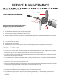
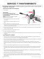
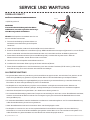
Propeller
Drive Pin
Anode/Nut
Washer
PROPELLER REPLACEMENT
TOOLS AND RESOURCES REQUIRED:
• Box End Wrench
- 1/2” for motors with 70 lbs thrust or lower.
- 9/16” for motors with 80 lbs thrust or higher.
• Screwdriver (optional)
CAUTION:
Disconnect the motor from the battery before
beginning any prop work or maintenance.
NOTE: The propeller on your motor may diff er from
the one pictured.
1. Disconnect motor from battery prior to changing the propeller.
2. Hold the propeller and loosen the anode/nut with a wrench.
3. Remove anode/nut and washer. If the drive pin is sheared/broken, you will need to hold the shaft steady with a screwdriver
blade pressed into the slot on the end of the shaft.
4. Turn the old prop to horizontal (as illustrated) and pull it straight off . If drive pin falls out, push it back in.
5. Align new propeller with drive pin.
6. Install prop washer and anode/nut.
7. Tighten anode/ nut 1/4 turn past snug. [25-35 inch lbs.] Be careful, over tightening can damage prop.
Tighten anode/ nut 1/4 turn past snug [25-35 inch lbs.] [2.5 to 4 Nm]. Be careful, over tightening can damage prop.
GENERAL MAINTENANCE
• After every use, the entire motor should be rinsed with freshwater, then wiped down with a cloth dampened with an aqueous
based silicone spray. Do not spray water into the ventilation openings in the head of the motor.
• The composite shaft requires periodic cleaning and lubrication for proper retraction and deployment. A coating of an aqueous
based silicone spray will improve operation.
• The propeller must be inspected and cleaned of weeds and fi shing line after every use. Fishing line and weeds can get behind
the prop, damage the seals and allow water to enter the motor.
• Verify the prop nut is secure each time the motor is used.
• To prevent accidental damage during transportation or storage, disconnect the battery whenever the motor is off of the water.
For prolonged storage, lightly coat all metal parts with an aqueous based silicone spray.
• For maximum battery life, recharge the battery(s) as soon as possible after use. For maximum motor performance, restore
battery to full charge prior to use.
• Keep battery terminals clean with fi ne sandpaper or emery cloth (fl ooded lead acid only).
• The propeller is designed to provide optimum operation with very high effi ciency. To maintain this top performance, the
leading edge of the blades must be kept smooth. If they are rough or nicked from use, restore to smooth by sanding with fi ne
sandpaper.
• 9'16" Box End Wrench
12 | minnkotamotors.com ©2015 Johnson Outdoors Marine Electronics, Inc.
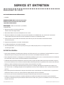
SERVICE & MAINTENANCE

FOR FURTHER TROUBLESHOOTING AND REPAIR
We off er several options to help you troubleshoot and/or repair your product. Please read through the options listed below.
FREQUENTLY ASKED QUESTIONS
We have FAQs available on our website to help answer all of your Minn Kota questions. Visit minnkotamotors.com and click on
“Frequently Asked Questions” to fi nd an answer to your question.
CALL US (FOR U.S. AND CANADA)
Our consumer service representatives are available Monday – Friday between 7:00 a.m. – 4:30 p.m. CST at 800-227-6433.
If you are calling to order parts, please have the 11-character serial number from your product, specifi c part numbers, and credit
card information available. This will help expedite your call and allow us to provide you with the best consumer service possible.
You can reference the parts list located in your manual to identify the specifi c part numbers.
EMAIL US
You can email our consumer service department with questions regarding your Minn Kota products. To email your question, visit
minnkotamotors.com and click on “Support”.
AUTHORIZED SERVICE CENTERS
Minn Kota has over 300 authorized service centers in the United States and Canada where you can purchase parts or get your
products repaired. Please visit our Authorized Service Center page on our website to locate a service center in your area.
Propeller
Drive Pin
Anode/Nut
Washer
PROPELLER REPLACEMENT
TOOLS AND RESOURCES REQUIRED:
• Box End Wrench
- 1/2” for motors with 70 lbs thrust or lower.
- 9/16” for motors with 80 lbs thrust or higher.
• Screwdriver (optional)
CAUTION:
Disconnect the motor from the battery before
beginning any prop work or maintenance.
NOTE: The propeller on your motor may diff er from
the one pictured.
1. Disconnect motor from battery prior to changing the propeller.
2. Hold the propeller and loosen the anode/nut with a wrench.
3. Remove anode/nut and washer. If the drive pin is sheared/broken, you will need to hold the shaft steady with a screwdriver
blade pressed into the slot on the end of the shaft.
4. Turn the old prop to horizontal (as illustrated) and pull it straight off . If drive pin falls out, push it back in.
5. Align new propeller with drive pin.
6. Install prop washer and anode/nut.
7. Tighten anode/ nut 1/4 turn past snug. [25-35 inch lbs.] Be careful, over tightening can damage prop.
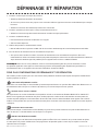
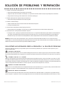
1. Motor fails to run or lacks power:
• Check battery connections for proper polarity.
• Make sure terminals are clean and corrosion free. Use fi ne sandpaper or emery cloth to clean terminals.
• Check battery water level. Add water if needed.
2. Motor loses power after a short running time:
• Check battery charge. If low, restore to full charge.
3. Motor is diffi cult to steer:
• Loosen the steering tension knob on the bracket
• Lubricate the composite shaft.
4. You experience prop vibration during normal operation:
• Remove and rotate the prop 180°. See removal instructions in the Propeller Replacement section.
5. Experiencing interference with your fi shfi nder:
• You may, in some applications, experience interference in your depth fi nder display. We recommend that you use a seperate
deep cycle marine battery for your trolling motor and that you power the depth fi nder from the starting/cranking battery. If
problems still persist, call our service department at 1-800-227-6433.
NOTE: For all other malfunctions, visit an Authorized Service Center. You can search for an Authorized Service Center in your
area by visiting our Authorized Service Center page, found online at minnkotamotors.com, or by calling our customer service
number, 800-227-6433.
GENERAL MAINTENANCE
• After every use, the entire motor should be rinsed with freshwater, then wiped down with a cloth dampened with an aqueous
based silicone spray. Do not spray water into the ventilation openings in the head of the motor.
• The composite shaft requires periodic cleaning and lubrication for proper retraction and deployment. A coating of an aqueous
based silicone spray will improve operation.
• The propeller must be inspected and cleaned of weeds and fi shing line after every use. Fishing line and weeds can get behind
the prop, damage the seals and allow water to enter the motor.
• Verify the prop nut is secure each time the motor is used.
• To prevent accidental damage during transportation or storage, disconnect the battery whenever the motor is off of the water.
For prolonged storage, lightly coat all metal parts with an aqueous based silicone spray.
• For maximum battery life, recharge the battery(s) as soon as possible after use. For maximum motor performance, restore
battery to full charge prior to use.
• Keep battery terminals clean with fi ne sandpaper or emery cloth (fl ooded lead acid only).
• The propeller is designed to provide optimum operation with very high effi ciency. To maintain this top performance, the
leading edge of the blades must be kept smooth. If they are rough or nicked from use, restore to smooth by sanding with fi ne
sandpaper.
minnkotamotors.com | 13
©2015 Johnson Outdoors Marine Electronics, Inc.
TROUBLESHOOTING & REPAIR

14 | minnkotamotors.com ©2015 Johnson Outdoors Marine Electronics, Inc.
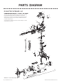
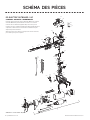
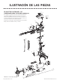
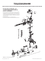
PARTS DIAGRAM
430
200
205
400
395
225
245
266 265
235
215
410
405
260 255
230
390
360
365
370 375
380
385 420
240
250
415
50
30
70
115
120
20
10
5
80
90
95 15
100
85
65
60
110
35
25
40
41
1010
1000
1020
1015
21
305 270
275
290
280
285
305
300
310
295
19
315
320
325
330
335
340
345
1
71
1025
1030
1035
220
135
136
425
1040
2094941 rev E ECN 37928 02/17
EO ELECTRIC OUTBOARD 1 HP
1 HORSEPOWER THRUST - 24 VOLT - 36” SHAFT
This page provides Minn Kota® WEEE compliance disassembly instructions.
For more information about where you should dispose of your waste
equipment for recycling and recovery and/or your European Union member
state requirements, please contact your dealer or distributor from which
your product was purchased.
Tools required, but not limited to: fl at head screw driver, Phillips screw driver,
socket set, pliers, wire cutters.

minnkotamotors.com | 15
©2015 Johnson Outdoors Marine Electronics, Inc.
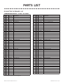
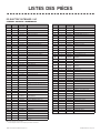
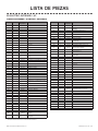
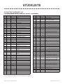
PARTS LIST
ITEM QTY PART
NUMBER DESCRIPTION
1 1 2317095 MOTOR ASSEMBLY 24V 4.5” SW 1 HP
5 1 2-100-250 ARMATURE ASSEMBLY
10 1140-014 BEARING
15 1788-040 RETAINING RING
19 12002011 TUBE COMPOSITE 36”
20 12-200-340 CENTER HOUSING ASSEMBY
21 1582-016 RETAINING CLIP
25 12-300-151 BRUSH END HOUSING ASSEMBLY
30 1421-241 PLAIN END HOUSING ASSEMBLY STD
35 1144-017 FLANGE BEARING (SERVICE ONLY)
40 2880-025 SEAL
41 1725-095 PAPER TUBE - SEAL BORE
50 2188-095 BRUSH
60 192-600-250 BRUSH PLATE ASSEMBLY
65 2975-045 BRUSH SPRING
n12881450 SEAL AND O-RING KIT [40, 70-80]
70 1701-098 O-RING, PLAIN END
71 1701-046 O-RING, BRUSH END
80 2701-009 O-RING, THRU-BOLT
85 22053410 SCREW, #8-32 X 1/2
90 2830-094 THRU-BOLT #12-24 X 10.31
95 1990-051 WASHER, STEEL
100 2990-052 WASHER, NYLATRON
110 12777312 FERRITE BEAD W/ SHRINK
115 1990-011 WASHER, SHIM
120 2992-011 WASHER, BELLEVILLE
135 1640-050 LEADWIRE, BLACK 10AWG 51-1/2
136 1640-150 LEADWIRE, RED 10WG 50-1/8”
200 12095687 DECAL, C-BOX COVER
205 12090201 C-BOX COVER
210 12074081 BATTERY METER, 24V SW
215 22043427 SCREW, #8 X 7/8 SS
220 12884112 CONTROL BOARD, 1HP 24V KIT
n12888400 POTENTIOMETER REPLACEMENT KIT
225 22303434 SCREW, #8-32 X 5/8 SS
230 12062538 CONTROL BOX, CAST, SW
235 12062905 STRAIN RELIEF
240 62303412 SCREW, #6 -20 X 5/8 SS
245 22063410 SCREW, #10-32 X 3/4” CAP SS
250 12093400 SCREW, #10-24 X 1-7/8” PPH SS
255 12061529 COLLAR, C-BOX
260 12333101 NUT, #10-24, NYLOCK, SS
265 12031520 COLLAR-DEPTH (W/O INSERT)
266 12011366 SCREW-COLLAR/NEW KNOB (SS)
ITEM QTY PART
NUMBER DESCRIPTION
n12991714 BRACKET ASSY, ALUMINUM [270-335]
270 12011366 KNOB, SCREW-COLLAR, SS
275 12062801 TENSION BLOCK
280 12077202 LEVER-TILT, TRANSOM BRACKET
285 12070512 PIN-HINGE, 1/8 X 1
290 12071863 HINGE-SW
295 12332700 SPRING-(T-BAR), SS
300 12333001 E-RING, SS
305 22037301 BUSHING, HINGE
310 12073604 T-BAR, (E-COAT)
315 12071947 BRACKET, DIE CAST SW
320 12070514 PIN-HINGE, 3/8 X 3.5, SS
325 22991303 CLAMP SCREW, HANDLE ASSY.
330 22331700 WASHER-CLAMP SCREW, SS
335 22263452 SCREW, 1/4-20 X 3/4 SHCS, SS
n12994844 BAG ASSEMBLY, TRANSOM EXTRUSION
340 22053421 SCREW 1/4-14 X 1 PFH, SS
345 12058415 TRANSOM EXTRUSION
n12990957 HANDLE ASSY, VARS [360-410]
360 12990456 GRIP/HANDLE ASSY, VARS [360-375]
365 22060015 BEARING, HANDLE
370 22063405 SCREW, #6 X 1/2 PFH SS
375 12884092 YOKE / SPIDER ASSY, VARS
380 12302742 SPRING, DETENT, OFF
385 22060005 BEARING, HANDLE PIVOT
390 12060900 HANDLE PIVOT, TOP
395 12302745 SPRING, RELEASE BUTTON
400 12063700 BUTTON, RELEASE
405 12060905 HANDLE PIVOT, BOTTOM
410 62303412 SCREW, #6-20 X 5/8 SS
415 12062715 SPRING, HANDLE PIVOT
420 12061700 WASHER, POT HOLDER
425 12881402 LEADWIRE ASSY, INCLUDES [235]
430 12307316 FERRITE BEAD
n11378160 PROPELLER KIT WW2 [1000-1020]
1000 12341160 PROPELLER WW2
1010 12262658 DRIVE PIN, LARGE
1015 12091701 WASHER, PROP, LARGE
1020 12198401 NUT, NYLOCK, PROP, ANODE
1025 12305415 SHRINK TUBE
1030 12305410 SHRINK TUBE
1035 42095400 SHRINK TUBE
1040 12096700 PLUG WIRE
n This item is part of an assembly.
* This item is part of a kit and only listed for viewing purposes.
EO ELECTRIC OUTBOARD 1 HP
1 HORSEPOWER THRUST - 24 VOLT - 36” SHAFT

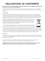
ENVIRONMENTAL COMPLIANCE STATEMENT:
It is the intention of JOME to be a responsible corporate citizen, operating in compliance with known and applicable
environmental regulations, and a good neighbor in the communities where we make or sell our products.
WEEE DIRECTIVE:
EU Directive 2002/96/EC “Waste of Electrical and Electronic Equipment Directive (WEEE)” impacts most distributors, sellers,
and manufacturers of consumer electronics in the European Union. The WEEE Directive requires the producer of consumer
electronics to take responsibility for the management of waste from their products to achieve environmentally responsible
disposal during the product life cycle.
WEEE compliance may not be required in your location for electrical & electronic equipment (EEE), nor may it be required
for EEE designed and intended as fi xed or temporary installation in transportation vehicles such as
automobiles, aircraft, and boats. In some European Union member states, these vehicles are considered
outside of the scope of the Directive, and EEE for those applications can be considered excluded from the
WEEE Directive requirement.
This symbol (WEEE wheelie bin) on product indicates the product must not be disposed of with other
household refuse. It must be disposed of and collected for recycling and recovery of waste EEE. Johnson
Outdoors Inc. will mark all EEE products in accordance with the WEEE Directive. It is our goal to comply
in the collection, treatment, recovery, and environmentally sound disposal of those products; however, these requirement do
vary within European Union member states. For more information about where you should dispose of your waste equipment for
recycling and recovery and/or your European Union member state requirements, please contact your dealer or distributor from
which your product was purchased.
DISPOSAL:
Minn Kota motors are not subject to the disposal regulations EAG-VO (electric devices directive) that implements the WEEE
directive. Nevertheless never dispose of your Minn Kota motor in a garbage bin but at the proper place of collection of your local
town council.
Never dispose of battery in a garbage bin. Comply with the disposal directions of the manufacturer or his representative and
dispose of them at the proper place of collection of your local town council.
WARNING: This product contains chemicals known to the State of California to cause cancer and birth defects
or other reproductive harm.
16 | minnkotamotors.com ©2015 Johnson Outdoors Marine Electronics, Inc.
COMPLIANCE STATEMENTS

ENVIRONMENTAL COMPLIANCE STATEMENT:
It is the intention of JOME to be a responsible corporate citizen, operating in compliance with known and applicable
environmental regulations, and a good neighbor in the communities where we make or sell our products.
WEEE DIRECTIVE:
EU Directive 2002/96/EC “Waste of Electrical and Electronic Equipment Directive (WEEE)” impacts most distributors, sellers,
and manufacturers of consumer electronics in the European Union. The WEEE Directive requires the producer of consumer
electronics to take responsibility for the management of waste from their products to achieve environmentally responsible
disposal during the product life cycle.
WEEE compliance may not be required in your location for electrical & electronic equipment (EEE), nor may it be required
for EEE designed and intended as fi xed or temporary installation in transportation vehicles such as
automobiles, aircraft, and boats. In some European Union member states, these vehicles are considered
outside of the scope of the Directive, and EEE for those applications can be considered excluded from the
WEEE Directive requirement.
This symbol (WEEE wheelie bin) on product indicates the product must not be disposed of with other
household refuse. It must be disposed of and collected for recycling and recovery of waste EEE. Johnson
Outdoors Inc. will mark all EEE products in accordance with the WEEE Directive. It is our goal to comply
in the collection, treatment, recovery, and environmentally sound disposal of those products; however, these requirement do
vary within European Union member states. For more information about where you should dispose of your waste equipment for
recycling and recovery and/or your European Union member state requirements, please contact your dealer or distributor from
which your product was purchased.
DISPOSAL:
Minn Kota motors are not subject to the disposal regulations EAG-VO (electric devices directive) that implements the WEEE
directive. Nevertheless never dispose of your Minn Kota motor in a garbage bin but at the proper place of collection of your local
town council.
Never dispose of battery in a garbage bin. Comply with the disposal directions of the manufacturer or his representative and
dispose of them at the proper place of collection of your local town council.
WARNING: This product contains chemicals known to the State of California to cause cancer and birth defects
or other reproductive harm.
minnkotamotors.com | 17
©2015 Johnson Outdoors Marine Electronics, Inc.
NOTES

A Johnson Outdoors Company
Minn Kota Consumer & Technical Service
Johnson Outdoors Marine Electronics, Inc.
PO Box 8129
Mankato, MN 56001
121 Power Drive
Mankato, MN 56001
Phone (800) 227-6433
Fax (800) 527-4464
minnkotamotors.com ©2016 Johnson Outdoors Marine Electronics, Inc.
All rights reserved.
Part #2097145 Rev B 2/16
ECN 36739
MK110P
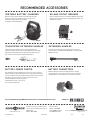
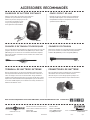
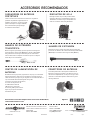
For a complete listing of Minn Kota accessories, visit minnkotamotors.com
RECOMMENDED ACCESSORIES
PORTABLE BATTERY CHARGERS
Bring the action right to the boat. Our Portable chargers
charge your battery in multiple stages to keep you on
the water longer, and they’re designed
to lengthen overall battery life.
60-AMP CIRCUIT BREAKER
Protects motor from electrical damage. 60 amp rating with
manual reset. Fully waterproof. Compatible with all 12-, 24-
and 36-volt systems.
TELESCOPING EXTENSION HANDLES EXTENSION HANDLES
Follow us:
BATTERY POWER CENTER
For small boat, transom applications, these easy access external
battery terminals allow trolling motor leads and charger leads to be
connected without opening the box. Built-in battery meter includes
two 12-volt accessory plugs, and two manual reset circuit
breakers (10 amp for accessory plugs
and 60 amp for motor). Fits group
24- and 27-size batteries.
BATTERY CONNECTORS
Patented design is ideal for installing batteries in tight,
confined places. Easy to disconnect for quick, convenient
charging. Plastic cover eliminates risk of electrical shock.
Simply twist the handle to loosen, adjust and tighten our
extension handles. Go from 17" to 25" (MKA-43) or 24" to 40"
(MKA-44) and experience total speed and steering control in
any situation. Fits all outboard and trolling motors.
Provides easier steering and speed control for all hand
control motors. Available in 18" (MKA-18) or extra-long 30"
(MKA-7) models.
MKR-19
M K A-7MKA-44 40"
MK-BC-1

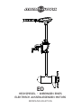
MOTEUR HORS-BORD ÉLECTRIQUE
EO
GUIDE DE L’UTILISATEUR

FRENCH - EUROPE
MODÈLE : ____________________________________________________________________________________________________________________
NUMÉRO DE SÉRIE : _______________________________________________________________________________________________________
DATE D’ACHAT : _____________________________________________________________________________________________________________
MAGASIN D’ACHAT : ________________________________________________________________________________________________________
REMARQUE : Ne retournez pas votre moteur Minn Kota à votre revendeur. Votre revendeur n’est pas autorisé à réparer ou à remplacer cette unité.
Vous pouvez faire une demande de réparations en appelant Minn Kota au +1 (800) 227-6433; en renvoyant votre moteur au centre de réparation
Minn Kota; ou en l’envoyant à un centre de service autorisé Minn Kota. Une liste des centres de réparation agréés est disponible sur notre site Web, à
l’adresse minnkotamotors.com. Veuillez inclure une preuve d’achat, le numéro de série de votre moteur et la date d’achat pour garantie avec l’une des
options ci-dessus.
Veuillez lire attentivement ce manuel d’utilisation. Suivez toutes les instructions et respectez toutes les mentions de mise en garde et mesures
de sécurité indiquées ci-dessous. Seules les personnes qui ont lu et compris ces instructions d’utilisation pourront utiliser ce moteur. Les mineurs ne
peuvent utiliser ce moteur que sous la supervision d’un adulte.
ATTENTION : Ne jamais faire fonctionner le moteur hors de l’eau, cette utilisation peut entraîner des blessures provoquées par l’hélice en rotation. Le
moteur doit être débranché de sa source d’alimentation quand il n’est pas en service ou hors de l’eau. Lors du raccordement des câbles d’alimentation
du moteur à la batterie, veillez à ce que ces derniers ne soient pas pliés ou tortillés, et câblés de manière à ce que personnes ne puisse trébucher. Avant
d’utiliser le moteur assurez-vous que l’isolation des câbles d’alimentation n’est pas endommagée. Le non-respect de ces consignes de sécurité peut
entraîner des court-circuit au niveau de la batterie et/ou du moteur. Débranchez toujours le moteur de la ou des batteries avant tout nettoyage ou
contrôle de l’hélice. Évitez d’immerger le moteur dans sa totalité, l’eau pourrait pénétrer dans l’unité inférieure de la tête de commande et dans l’arbre.
Si le moteur est utilisé tandis que de l’eau est présente dans son unité inférieure, des dommages considérables peuvent survenir. Ces dommages ne
seront pas couverts par la garantie.
MISE EN GARDE : Veillez à ce que ni vous ni d’autres personnes n’approchiez l’hélice de trop près, quand elle est en mouvement ni avec les parties
du corps, ni avec des objets. Le moteur est puissant et peut vous mettre en danger ou vous blesser, ou blesser quelqu’un. Lorsque le moteur tourne
prenez garde aux personnes qui nagent et aux objets fl ottants. Les personnes dont la capacité à faire fonctionner le moteur ou dont les réactions ont
été amoindries par l’alcool, les drogues, les médicaments ou d’autres substances ne sont pas autorisées à utiliser ce moteur. Ce moteur ne convient pas
à une utilisation par forts courants. Le niveau de bruit constant du moteur en cours d’utilisation est inférieur à 70dB (A). Le niveau de vibration global
ne dépasse pas 2,5 m/sec2.
MERCI
Merci d’avoir choisi Minn Kota. Nous pensons que vous devriez passer plus de temps à pêcher et moins de temps à positionner
votre bateau. C’est pour cette raison que nous construisons les moteurs les plus intelligents, les plus solides et les plus intuitifs.
Chaque aspect d’un moteur Minn Kota est pensé et repensé jusqu’à ce qu’il mérite de porter notre nom. D’innombrables heures de
recherche et de tests vous off rent l’avantage d’un Minn Kota qui peut vraiment vous emmener « n’importe où. N’importe quand.
» Nous ne croyons pas aux raccourcis. Nous sommes Minn Kota. Et nous nous désirons toujours vous aider à attraper plus de
poissons.
N’OUBLIEZ PAS DE CONSERVER VOTRE REÇU ET D’ENREGISTRER IMMÉDIATEMENT VOTRE MOTEUR.
Une carte d’enregistrement est jointe, ou vous pouvez terminer l’enregistrement sur notre site Web à l’adresse minnkotamotors.com.
REPÉRER VOTRE NUMÉRO DE SÉRIE
Le numéro de série à 11 caractères de votre Minn Kota est très important. Il aide à déterminer un modèle et une année de fabrication spécifi ques.
Lorsque vous contactez le Service clientèle ou enregistrez votre produit, vous aurez besoin de connaître le numéro de série de ce dernier. Nous vous
recommandons d’inscrire le numéro de série dans l’espace prévu ci-dessous afi n de l’avoir à votre disposition et de le consulter ultérieurement.
GUIDE DE L’UTILISATEUR PRINCIPAL CE (POUR LES MODÈLES CERTIFIÉS CE/C-TICK)
Conforme aux normes 89/336/CEE (CEM), EN 55022A, EN 50082-2 depuis 1996 LN V9677264
20 | minnkotamotors.com ©2015 Johnson Outdoors Marine Electronics, Inc.
Made by Minn Kota
Johnson Outdoors
Marine Electronics, Inc.
121 Power Drive
Mankato, MN 56001 USA
Outboard Motors
Produced in 2015
EO - 1/2 HP
MODEL 1363880
SER NO M365 MK12345
Le numéro de série de votre moteur
EO est situé sous sa poignée.
EXEMPLE
La page est en cours de chargement...
La page est en cours de chargement...
La page est en cours de chargement...
La page est en cours de chargement...
La page est en cours de chargement...
La page est en cours de chargement...
La page est en cours de chargement...
La page est en cours de chargement...
La page est en cours de chargement...
La page est en cours de chargement...
La page est en cours de chargement...
La page est en cours de chargement...
La page est en cours de chargement...
La page est en cours de chargement...
La page est en cours de chargement...
La page est en cours de chargement...
La page est en cours de chargement...
La page est en cours de chargement...
La page est en cours de chargement...
La page est en cours de chargement...
La page est en cours de chargement...
La page est en cours de chargement...
La page est en cours de chargement...
La page est en cours de chargement...
La page est en cours de chargement...
La page est en cours de chargement...
La page est en cours de chargement...
La page est en cours de chargement...
La page est en cours de chargement...
La page est en cours de chargement...
La page est en cours de chargement...
La page est en cours de chargement...
La page est en cours de chargement...
La page est en cours de chargement...
La page est en cours de chargement...
La page est en cours de chargement...
La page est en cours de chargement...
La page est en cours de chargement...
La page est en cours de chargement...
La page est en cours de chargement...
La page est en cours de chargement...
La page est en cours de chargement...
La page est en cours de chargement...
La page est en cours de chargement...
La page est en cours de chargement...
La page est en cours de chargement...
La page est en cours de chargement...
La page est en cours de chargement...
La page est en cours de chargement...
La page est en cours de chargement...
La page est en cours de chargement...
La page est en cours de chargement...
-
 1
1
-
 2
2
-
 3
3
-
 4
4
-
 5
5
-
 6
6
-
 7
7
-
 8
8
-
 9
9
-
 10
10
-
 11
11
-
 12
12
-
 13
13
-
 14
14
-
 15
15
-
 16
16
-
 17
17
-
 18
18
-
 19
19
-
 20
20
-
 21
21
-
 22
22
-
 23
23
-
 24
24
-
 25
25
-
 26
26
-
 27
27
-
 28
28
-
 29
29
-
 30
30
-
 31
31
-
 32
32
-
 33
33
-
 34
34
-
 35
35
-
 36
36
-
 37
37
-
 38
38
-
 39
39
-
 40
40
-
 41
41
-
 42
42
-
 43
43
-
 44
44
-
 45
45
-
 46
46
-
 47
47
-
 48
48
-
 49
49
-
 50
50
-
 51
51
-
 52
52
-
 53
53
-
 54
54
-
 55
55
-
 56
56
-
 57
57
-
 58
58
-
 59
59
-
 60
60
-
 61
61
-
 62
62
-
 63
63
-
 64
64
-
 65
65
-
 66
66
-
 67
67
-
 68
68
-
 69
69
-
 70
70
-
 71
71
-
 72
72


MINN KOTA MINN-KOTA 1363885 EO Transom Mount Electric Outboard Motor Manuel utilisateur
- Taper
- Manuel utilisateur
dans d''autres langues
Documents connexes
-
MINN KOTA ENDURA MAX 30 lb Manuel utilisateur
-
-
-
-
-
-
-
MINN KOTA POWERDRIVE V2 Manuel utilisateur
-