
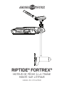
RIPTIDE
®
FORTREX
®
BOW-MOUNT TROLLING MOTOR
USER MANUAL

Model: _________________________________________________________________________________________________________________________
Serial Number: _______________________________________________________________________________________________________________
Purchase Date: _______________________________________________________________________________________________________________
Store Where Purchased: ____________________________________________________________________________________________________
NOTE: Do not return your Minn Kota motor to your retailer. Your retailer is not authorized to repair or replace this unit. You may obtain service
by: calling Minn Kota at (800) 227-6433; returning your motor to the Minn Kota Factory Service Center; sending or taking your motor to any
Minn Kota authorized service center. A list of authorized service centers is available on our website, at minnkotamotors.com. Please include proof of
purchase, serial number and purchase date for warranty service with any of the above options.
Please thoroughly read this user manual. Follow all instructions and heed all safety and cautionary notices below. Use of this motor is only
permitted for persons that have read and understood these user instructions. Minors may use this motor only under adult supervision.
ATTENTION: Never run the motor out of the water, as this may result in injuries from the rotating propeller. The motor should be disconnected from
the power source when it is not in use or is off the water. When connecting the power-supply cables of the motor to the battery, ensure that they are
not kinked or subject to chafe and route them in such a way that persons cannot trip over them. Before using the motor make sure that the insulation
of the power cables is not damaged. Disregarding these safety precautions may result in electric shorts of battery(s) and/or motor. Always disconnect
motor from battery(s) before cleaning or checking the propeller. Avoid submerging the complete motor as water may enter the lower unit through
control head and shaft. If the motor is used while water is present in the lower unit considerable damage to the motor can occur. This damage will not
be covered by warranty.
CAUTION: Take care that neither you nor other persons approach the turning propeller too closely, neither with body parts nor with objects. The
motor is powerful and may endanger or injure you or others. While the motor is running watch out for persons swimming and for fl oating objects.
Persons whose ability to run the motor or whose reactions are impaired by alcohol, drugs, medication, or other substances are not permitted to use
this motor. This motor is not suitable for use in strong currents. The constant noise pressure level of the motor during use is less than 70dB(A). The
overall vibration level does not exceed 2,5m/sec2.
THANK YOU
Thank you for choosing Minn Kota. We believe that you should spend more time fi shing and less time positioning your boat.
That’s why we build the smartest, toughest, most intuitive trolling motors on the water. Every aspect of a Minn Kota trolling motor
is thought out and rethought until it’s good enough to bear our name. Countless hours of research and testing provide you the
Minn Kota advantage that can truly take you “Anywhere. Anytime.” We don’t believe in shortcuts. We are Minn Kota. And we are
never done helping you catch more fi sh.
REMEMBER TO KEEP YOUR RECEIPT AND IMMEDIATELY REGISTER YOUR TROLLING MOTOR.
A registration card is enclosed or you can complete registration on our website at minnkotamotors.com.
LOCATING YOUR SERIAL NUMBER
Your Minn Kota 11-character serial number is very important. It helps to determine the specifi c model and year of manufacture. When contacting
Consumer Service or registering your product, you will need to know your product’s serial number. We recommend that you write the serial number
down in the space provided below so that you have it available for future reference.
CE MASTER USER MANUAL (FOR CE/C-TICK CERTIFIED MODELS)
2 | minnkotamotors.com
©2015 Johnson Outdoors Marine Electronics, Inc.
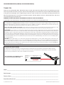
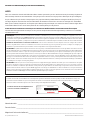
The serial number on your Riptide Fortrex is
located located under the tiller handle.
Made by Minn Kota
Johnson Outdoors
Marine Electronics, Inc.
121 Power Drive
Mankato, MN 56001 USA
Trolling Motors
Produced in 2014
Riptide Fortrex 112/62
MODEL 1363660
SER NO M365 MK12345
EXAMPLE

minnkotamotors.com | 3
©2015 Johnson Outdoors Marine Electronics, Inc.
TABLE OF CONTENTS
Two-Year Limited Warranty 4
Features 5
Mount Installation 6-9
Battery & Wiring Installation 10-11
Boat Rigging & Product Installation 10
Conductor Gauge and Circuit Breaker Sizing Table 10
Push-to-Test Battery Meter 10
Selecting the Correct Batteries 11
How to Connect Batteries 11
Motor Wiring Diagram 12
Using & Adjusting The Motor 13-15
Stowing & Deploying the Motor 13
Adjusting the Depth of the Motor 14
Controlling Speed and Direction with the Tiller 14
Adjusting the Tilt/Extend Tiller 15
Service & Maintenance 16
Propeller Replacement 16
General Maintenance 16
Troubleshooting & Repair 17
Environmental Compliance Statements 18
Parts Diagram 19
Parts List 20-21

WARRANTY ON MINN KOTA SALTWATER TROLLING MOTORS
Johnson Outdoors Marine Electronics, Inc. (“JOME”) extends the following limited warranty to the original retail purchaser only. Warranty coverage is not
transferable.
MINN KOTA LIMITED TWO-YEAR WARRANTY ON THE ENTIRE PRODUCT
JOME warrants to the original retail purchaser only that the purchaser’s new Minn Kota saltwater trolling motor will be materially free from defects in materials
and workmanship appearing within two (2) years after the date of purchase. JOME will (at its option) either repair or replace, free of charge, any parts found by
JOME to be defective during the term of this warranty. Such repair, or replacement shall be the sole and exclusive liability of JOME and the sole and exclusive
remedy of the purchaser for breach of this warranty.
MINN KOTA LIMITED LIFETIME WARRANTY ON COMPOSITE SHAFT
JOME warrants to the original retail purchaser only that the composite shaft of the purchaser’s Minn Kota trolling motor will be materially free from defects in
materials and workmanship appearing within the original purchaser’s lifetime. JOME will provide a new composite shaft, free of charge, to replace any composite
shaft found by JOME to be defective during the term of this warranty. Providing a new composite shaft shall be the sole and exclusive liability of JOME and the
sole and exclusive remedy of the purchaser for breach of this warranty; and purchaser shall be responsible for installing, or for the cost of labor to
install, any new composite shaft provided by JOME.
EXCLUSIONS & LIMITATIONS
This limited warranty does not apply to products that have been used commercially or for rental purposes. This limited warranty does not cover normal wear
and tear, blemishes that do not aff ect the operation of the product, or damage caused by accidents, abuse, alteration, modifi cation, shipping damages, acts
of God, negligence of the user or misuse, improper or insuffi cient care or maintenance. DAMAGE CAUSED BY THE USE OF OTHER REPLACEMENT
PARTS NOT MEETING THE DESIGN SPECIFICATIONS OF THE ORIGINAL PARTS WILL NOT BE COVERED BY THIS LIMITED WARRANTY.
The cost of normal maintenance or replacement parts which are not in breach of the limited warranty are the responsibility of the purchaser. Prior to using
products, the purchaser shall determine the suitability of the products for the intended use and assumes all related risk and liability. Any assistance JOME
provides to or procures for the purchaser outside the terms, limitations or exclusions of this limited warranty will not constitute a waiver of the terms, limitations
or exclusions, nor will such assistance extend or revive the warranty. JOME will not reimburse the purchaser for any expenses incurred by the purchaser
in repairing, correcting or replacing any defective products or parts, except those incurred with JOME’s prior written permission. JOME’S AGGREGATE
LIABILITY WITH RESPECT TO COVERED PRODUCTS IS LIMITED TO AN AMOUNT EQUAL TO THE PURCHASER’S ORIGINAL PURCHASE
PRICE PAID FOR SUCH PRODUCT.
MINN KOTA SERVICE INFORMATION
To obtain warranty service in the U.S., the product believed to be defective, and proof of original purchase (including the date of purchase), must be presented
to a Minn Kota Authorized Service Center or to Minn Kota’s factory service center in Mankato, MN. Any charges incurred for service calls, transportation or
shipping/freight to/from the Minn Kota Authorized Service Center or factory, labor to haul out, remove, re-install or re-rig products removed for warranty service,
or any other similar items are the sole and exclusive responsibility of the purchaser. Products purchased outside of the U.S. must be returned prepaid with
proof of purchase (including the date of purchase and serial number) to any Authorized Minn Kota Service Center in the country of purchase. Warranty service
can be arranged by contacting a Minn Kota Authorized Service Center or by contacting the factory at 1-800-227-6433 or email service@minnkotamotors.com.
Products repaired or replaced will be warranted for the remainder of the original warranty period [or for 90 days from the date of repair
or replacement, whichever is longer]. For any product that is returned for warranty service that JOME fi nds to be not covered by or not
in breach of this limited warranty, there will be a billing for services rendered at the prevailing posted labor rate and for a minimum of at
least one hour.
NOTE: Do not return your Minn Kota product to your retailer. Your retailer is not authorized to repair or replace products.
THERE ARE NO EXPRESS WARRANTIES OTHER THAN THESE LIMITED WARRANTIES. IN NO EVENT SHALL ANY IMPLIED
WARRANTIES INCLUDING ANY IMPLIED WARRANTIES OF MERCHANTABILITY OR FITNESS FOR PARTICULAR PURPOSE, EXTEND
BEYOND THE DURATION OF THE RELEVANT EXPRESS LIMITED WARRANTY. IN NO EVENT SHALL JOME BE LIABLE FOR PUNITIVE,
INDIRECT, INCIDENTAL, CONSEQUENTIAL OR SPECIAL DAMAGES. Without limiting the foregoing, JOME assumes no responsibility for
loss of use of product, loss of time, inconvenience or other damage.
Some states do not allow limitations on how long an implied warranty lasts or the exclusion or limitation of incidental or consequential damages, so the above
limitations and/or exclusions may not apply to you. This warranty gives you specifi c legal rights and you may also have other legal rights which vary from state
to state.
4 | minnkotamotors.com
©2015 Johnson Outdoors Marine Electronics, Inc.
TWO-YEAR LIMITED WARRANTY

WARRANTY ON MINN KOTA SALTWATER TROLLING MOTORS
Johnson Outdoors Marine Electronics, Inc. (“JOME”) extends the following limited warranty to the original retail purchaser only. Warranty coverage is not
transferable.
MINN KOTA LIMITED TWO-YEAR WARRANTY ON THE ENTIRE PRODUCT
JOME warrants to the original retail purchaser only that the purchaser’s new Minn Kota saltwater trolling motor will be materially free from defects in materials
and workmanship appearing within two (2) years after the date of purchase. JOME will (at its option) either repair or replace, free of charge, any parts found by
JOME to be defective during the term of this warranty. Such repair, or replacement shall be the sole and exclusive liability of JOME and the sole and exclusive
remedy of the purchaser for breach of this warranty.
MINN KOTA LIMITED LIFETIME WARRANTY ON COMPOSITE SHAFT
JOME warrants to the original retail purchaser only that the composite shaft of the purchaser’s Minn Kota trolling motor will be materially free from defects in
materials and workmanship appearing within the original purchaser’s lifetime. JOME will provide a new composite shaft, free of charge, to replace any composite
shaft found by JOME to be defective during the term of this warranty. Providing a new composite shaft shall be the sole and exclusive liability of JOME and the
sole and exclusive remedy of the purchaser for breach of this warranty; and purchaser shall be responsible for installing, or for the cost of labor to
install, any new composite shaft provided by JOME.
EXCLUSIONS & LIMITATIONS
This limited warranty does not apply to products that have been used commercially or for rental purposes. This limited warranty does not cover normal wear
and tear, blemishes that do not aff ect the operation of the product, or damage caused by accidents, abuse, alteration, modifi cation, shipping damages, acts
of God, negligence of the user or misuse, improper or insuffi cient care or maintenance. DAMAGE CAUSED BY THE USE OF OTHER REPLACEMENT
PARTS NOT MEETING THE DESIGN SPECIFICATIONS OF THE ORIGINAL PARTS WILL NOT BE COVERED BY THIS LIMITED WARRANTY.
The cost of normal maintenance or replacement parts which are not in breach of the limited warranty are the responsibility of the purchaser. Prior to using
products, the purchaser shall determine the suitability of the products for the intended use and assumes all related risk and liability. Any assistance JOME
provides to or procures for the purchaser outside the terms, limitations or exclusions of this limited warranty will not constitute a waiver of the terms, limitations
or exclusions, nor will such assistance extend or revive the warranty. JOME will not reimburse the purchaser for any expenses incurred by the purchaser
in repairing, correcting or replacing any defective products or parts, except those incurred with JOME’s prior written permission. JOME’S AGGREGATE
LIABILITY WITH RESPECT TO COVERED PRODUCTS IS LIMITED TO AN AMOUNT EQUAL TO THE PURCHASER’S ORIGINAL PURCHASE
PRICE PAID FOR SUCH PRODUCT.
MINN KOTA SERVICE INFORMATION
To obtain warranty service in the U.S., the product believed to be defective, and proof of original purchase (including the date of purchase), must be presented
to a Minn Kota Authorized Service Center or to Minn Kota’s factory service center in Mankato, MN. Any charges incurred for service calls, transportation or
shipping/freight to/from the Minn Kota Authorized Service Center or factory, labor to haul out, remove, re-install or re-rig products removed for warranty service,
or any other similar items are the sole and exclusive responsibility of the purchaser. Products purchased outside of the U.S. must be returned prepaid with
proof of purchase (including the date of purchase and serial number) to any Authorized Minn Kota Service Center in the country of purchase. Warranty service
can be arranged by contacting a Minn Kota Authorized Service Center or by contacting the factory at 1-800-227-6433 or email service@minnkotamotors.com.
Products repaired or replaced will be warranted for the remainder of the original warranty period [or for 90 days from the date of repair
or replacement, whichever is longer]. For any product that is returned for warranty service that JOME fi nds to be not covered by or not
in breach of this limited warranty, there will be a billing for services rendered at the prevailing posted labor rate and for a minimum of at
least one hour.
NOTE: Do not return your Minn Kota product to your retailer. Your retailer is not authorized to repair or replace products.
THERE ARE NO EXPRESS WARRANTIES OTHER THAN THESE LIMITED WARRANTIES. IN NO EVENT SHALL ANY IMPLIED
WARRANTIES INCLUDING ANY IMPLIED WARRANTIES OF MERCHANTABILITY OR FITNESS FOR PARTICULAR PURPOSE, EXTEND
BEYOND THE DURATION OF THE RELEVANT EXPRESS LIMITED WARRANTY. IN NO EVENT SHALL JOME BE LIABLE FOR PUNITIVE,
INDIRECT, INCIDENTAL, CONSEQUENTIAL OR SPECIAL DAMAGES. Without limiting the foregoing, JOME assumes no responsibility for
loss of use of product, loss of time, inconvenience or other damage.
Some states do not allow limitations on how long an implied warranty lasts or the exclusion or limitation of incidental or consequential damages, so the above
limitations and/or exclusions may not apply to you. This warranty gives you specifi c legal rights and you may also have other legal rights which vary from state
to state.
minnkotamotors.com | 5
©2015 Johnson Outdoors Marine Electronics, Inc.
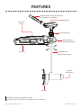
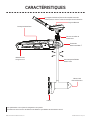
FEATURES
Specifications subject to change without notice.
This diagram is for reference only and may differ from your actual motor.
BowGuard 360° ®
Breakaway Protection
Battery Meter
Lifetime Warranty
Flexible Composite Shaft
Propeller
Mono-Arm
Design
Cool Quiet
Power Motor
Lift-Assist
Depth Collar Knob
Tilt/Extend Tiller Controls: On/Off, Speed,
Forward/Reverse and Direction

6 | minnkotamotors.com
©2015 Johnson Outdoors Marine Electronics, Inc.
MOUNT INSTALLATION
TOOLS AND RESOURCES REQUIRED:
• Phillips Screw Driver
• 1/4” Allen Wrench
• Drill
• 9/32” Drill Bit
• 7/16” Box End Wrench
• A second person to help with the installation
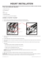
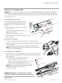
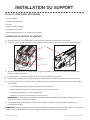
ASSEMBLY OF MOTOR TO MOUNT
1. Place the mount on an elevated surface such as a workbench or tailgate of pickup.
2. Remove the 5/16” Allen screw and lock washer from the mount using an Allen wrench.
3. Align the key ways on the inside of the Bowguard with the end links on the mount. Lower the motor assembly straight down
until seated.
4. Install the 5/16” Allen screw / lock washer and tighten to 10-12 ft/lbs.
5. Stow the motor into the fl at position by pulling the rope/handle to disengage the latch bar, allowing the motor to fold into the
fl at position.
6. Once in the stowed or fl at position, the gas spring pin can be installed. Follow the steps below to install the gas spring pin
and spacers:
• Locate the upper gas spring pin and spacers in bag assembly
• Align the end of the gas spring with the holes in the outer arm.
• Install pin, spacers and Phillips fl at head screws,
• Tighten screws until the heads are fl ush with the outer arm.
NOTE: Screws have a pre-applied thread locker, DO NOT apply additional thread locker to screws as that may
prevent future removal
7. Motor / mount can now be installed onto the boat. Proceed to next page for mounting instructions.
ATTENTION: The 5/16” Allen screw must be tight when installed and periodically tightened to 10-12 ft/lbs (Step 4), which will
allow the motor to be stowed properly. Tighten the Allen screw when the mount is in the deployed position.
Allen Screw
Keys
Safety Latch

minnkotamotors.com | 7
©2015 Johnson Outdoors Marine Electronics, Inc.
MOUNT INSTALLATION
2
1
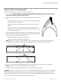
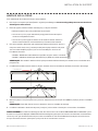
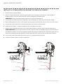
INSTALLATION OF THE BOW-MOUNT
We recommend that you have another person help with this procedure.
1. For installation, DO NOT REMOVE THE SHAFT/MOTOR FROM THE BOWGUARD. The Bowguard spring is
under tension and must always remain secured.
2. Place the mount, with the motor in the fully stowed (fl at) position, on the deck of the
boat:
• The motor should be mounted as close to the centerline of the boat as possible
when it is deployed (see illustration).
• Make sure bow area under the chosen location is clear and unobstructed for
drilling.
• Make sure the motor rest is positioned far enough beyond the edge of the
boat. The motor, as it is lowered into the water or raised into the boat, must not
encounter any obstructions
3. Once in position, determine which bolt pattern to use (see below), mark at least 4
of the holes (2 on each side) in the bow plate and drill through with a 9/32” drill bit.
Either pattern may be used when installing the motor.
- Pattern 1: Minnkota 3” bolt pattern standard motors.
- Pattern 2: Alternate 4” bolt pattern commonly used.
NOTE: If pattern 2 is to be used, the right side plate must be removed to access the mounting holes in the bow plate.
4. Install hold down strap between the motor and deck of boat between second and third set of mounting holes.
5. Mount the plate to the bow through the drilled holes using the provided (1/4-20 x 3-1/2”) bolts, nuts and washers.
NOTE: If possible, secure all sets of mounting bolts, nuts and washers.
6. Install the bow mount stabilizer (if included). See next section for installation instructions.
WARNING: The gas assist lift mechanism in this unit is under HIGH SPRING PRESSURE when the motor is in the deployed
position. DO NOT remove the Bowguard assembly from the mount without disconnecting one end of the gas spring (see
Removal of Bowguard section). Failure to do this can create a condition where accidental pulling of the rope may cause the
mount to spring open rapidly, striking anyone or anything in the direct path.
Hold Down Strap

8 | minnkotamotors.com
©2015 Johnson Outdoors Marine Electronics, Inc.
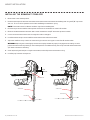
MOUNT INSTALLATION
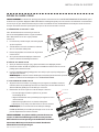
Stabilizer Rod
3/4”
19.1mm
Stabilizer Rod
Bottom Bumper
Threaded End
Stabilizer Bracket
INSTALLING THE BOWMOUNT STABILIZER
1. Place motor in the stowed position.
2. Unthread the composite rod from the bracket and attach bracket to the bottom of the Bowguard using the 5/16” cap screws
and nuts. The nuts fi t into pocket on the inside of the Bowguard behind the spring.
NOTE: The bracket can be installed on the left or right side of the Bowguard.
3. Pull the bumper off the stabilizer rod and place the rod next to the bracket as shown in illustration.
4. Place the threaded end down onto the deck surface and mark the rod 3/4” above the top of the bracket.
5. Cut the rod to the mark and round the cut edge with a fi le or sandpaper.
6. Install the bottom bumper to the stabilizer rod and thread the rod into the bracket.
7. Adjust the stabilizer rod up or down to so that the tip just touches the support surface. See illustration below.
WARNING: Adjusting the rod too tightly removes the end play needed for proper pin engagement and doing so could
prevent the mount from fully latching in the stowed position. If installed correctly, the rod tip should lift off the deck about
1/4” without the mount unlatching.
8. Once adjusted, tighten the jam nut against the bracket, which will prevent the rod from turning.
9. Install top cap if threads are exposed.

minnkotamotors.com | 9
©2015 Johnson Outdoors Marine Electronics, Inc.
MOUNT INSTALLATION
REMOVAL OF THE BOWGUARD
WARNING: The gas assist lift mechanism in this unit is under HIGH SPRING PRESSURE when the motor is in the deployed
position. DO NOT remove the Bowguard assembly from the mount without disconnecting one end of the gas spring. Failure to
do this can create a condition where accidental pulling of the rope may cause the mount to spring open rapidly, striking anyone or
anything in the direct path.
A) DISCONNECT THE GAS SPRING:
You must disconnect the gas spring before removing
the Bowguard assembly from the motor mount. To
disconnect the gas springs, follow the instructions
below:
1. With the mount in the stowed position, locate the
upper cylinder pin.
2. Using two Phillips screwdrivers, remove 1 of the
Phillips fl at head screws.
3. Remove pin and spacers from outer arm.
4. Now it is safe to deploy the motor and remove the
motor assembly.
B) REMOVE THE BOWGUARD
1. Once you disconnect the gas spring, place the motor in the deployed position.
2. Remove the 5/16” cap screw and lock washer located on the top of the Bowguard, in
front of the pull rope.
3. Lift motor/Bowguard assembly straight up until Bowguard is free from mount.
NOTE: Rope and latch bar should never be pulled with the motor removed as the
assembly is under HIGH PRESSURE.
C) RE-ASSEMBLING THE BOWGUARD
1. Align the key ways on the inside of the Bowguard with the ends links on the mount.
Lower the assembly straight down until seated Re-install the 5/16” cap screw and
washer and tighten.
2. Reconnect the gas spring by following the steps below:
• Locate the upper gas spring pin and spacers.
• Align the end of the gas spring with the holes in the outer arm.
• Install pin, spacers and Phillips fl at head screws,
• Tighten screws until the heads are fl ush with the outer arm.
NOTE: Screws have a pre-applied thread locker, DO NOT apply
additional thread locker to screws as that may
prevent future removal.
WARNING: Moving parts can crush or cut. Gas assist lift
mechanism is under pressure. Disconnect gas spring before
removing motor from mount. Do not pull rope until gas spring
is disconnected.
Phillips Screw
Gas Spring
Allen Screw
Yoke
Phillips Screw
Spacer
Gas Spring Pin

BOAT RIGGING & PRODUCT INSTALLATION
For safety and compliance reasons, we recommend that you follow American Boat and Yacht Council (ABYC) standards when
rigging your boat. Altering boat wiring should be completed by a qualifi ed marine technician. The following specifi cations are for
general guidelines only:
CAUTION: These guidelines apply to general rigging to support your Minn Kota motor. Powering multiple motors or additional
electrical devices from the same power circuit may impact the recommended conductor gauge and circuit breaker size. If you are
using wire longer than that provided with your unit, follow the conductor gauge and circuit breaker sizing table below. If your wire
extension length is more than 25 feet, we recommend that you contact a qualifi ed marine technician.
An over-current protection device (circuit breaker or fuse) must be used. Coast Guard requirements dictate that
each ungrounded current-carrying conductor must be protected by a manually reset, trip-free circuit breaker or fuse. The type
(voltage and current rating) of the fuse or circuit breaker must be sized accordingly to the trolling motor used. The table below gives
recommended guidelines for circuit breaker sizing.
Reference:
United States Code of Federal Regulations: 33 CFR 183 – Boats and Associated Equipment
ABYC E-11: AC and DC Electrical Systems on Boats
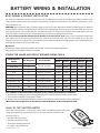
CONDUCTOR GAUGE AND CIRCUIT BREAKER SIZING TABLE
Motor Thrust /
Model
Max Amp Draw Circuit Breaker
Wire Extension Length *
5 feet 10 feet 15 feet 20 feet 25 feet
30 lb. 30
50 Amp @ 12 VDC
10 AWG 10 AWG 8 AWG 6 AWG 4 AWG
40 lb., 45 lb. 42 10 AWG 8 AWG 6 AWG 4 AWG 4 AWG
50 lb., 55 lb. 50 60 Amp @ 12 VDC 8 AWG 6 AWG 4 AWG 4 AWG 2 AWG
70 lb. 42 50 Amp @ 24 VDC 10 AWG 10 AWG 8 AWG 8 AWG 6 AWG
80 lb. 56 60 Amp @ 24 VDC 8 AWG 8 AWG 8 AWG 6 AWG 6 AWG
101 lb. 46 50 Amp @ 36 VDC 8 AWG 8 AWG 8 AWG 8 AWG 8 AWG
Engine Mount 101 50 60 Amp @ 36 VDC 8 AWG 6 AWG 4 AWG 4 AWG 2 AWG
112 lb. 52 60 Amp @ 36 VDC 8 AWG 8 AWG 8 AWG 8 AWG 8 AWG
Engine Mount 160 116 (2) x 60 Amp @ 24 VDC 2 AWG 2 AWG 2 AWG 2 AWG 2 AWG
E-Drive 40 50 Amp @ 48 VDC 10 AWG 10 AWG 10 AWG 10 AWG 10 AWG
This conductor and circuit breaker sizing table is only valid for the following assumptions:
1. No more than 3 conductors are bundled together inside of a sheath or conduit outside of engine spaces.
2. Each conductor has 105° C temp rated insulation.
3. No more than 5% voltage drop allowed at full motor power based on published product power requirements.
*Wire Extension Length refers to the distance from the batteries to the trolling motor leads.
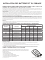
PUSH-TO-TEST BATTERY METER
This motor is equipped with a “push-to-test” battery meter. The LED light provides an accurate
display of the remaining charge in the battery. It is only accurate when the motor is off .
The meter reads as:
• One light indicates recharge.
• Two lights indicate low charge.
• Three lights indicate good charge.
• Four lights indicate full charge.
Test with
Motor Off
10 | minnkotamotors.com
©2015 Johnson Outdoors Marine Electronics, Inc.
BATTERY WIRING & INSTALLATION

SELECTING THE CORRECT BATTERIES
The motor will operate with any lead acid, deep cycle marine 12 volt battery/batteries. For best results, use a deep cycle, marine
battery with at least a 105 ampere hour rating. Maintain battery at full charge. Proper care will ensure having battery power
when you need it, and will signifi cantly improve the battery life. Failure to recharge lead-acid batteries (within 12-24 hours) is the
leading cause of premature battery failure. Use a multi-stage charger to avoid overcharging. We off er a wide selection of chargers
to fi t your charging needs. If you are using a crank battery to start a gasoline outboard, we recommend that you use a separate
deep cycle marine battery/batteries for your Minn Kota trolling motor.
Advice Regarding Batteries:
• Never connect the (+) and the (–) terminals of the same battery together. Take care that no metal object can fall onto the
battery and short the terminals. This would immediately lead to a short and extreme fi re danger.
• It is highly recommended that a circuit breaker or fuse be used with this trolling motor. Refer to “Conductor Gauge and Circuit
Breaker Sizing Table” in the previous section to fi nd the appropriate circuit breaker or fuse for your motor. For motors requiring
a 60-amp breaker, the Minn Kota MKR-19 60-amp circuit breaker is recommended.
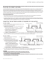
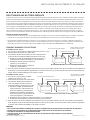
CONNECTING THE BATTERIES IN SERIES (IF REQUIRED FOR YOUR MOTOR)
24 VOLT SYSTEMS:
1. Make sure that the motor is switched off (speed selector on “0”).
2. Two 12 volt batteries are required.
3. The batteries must be wired in series, only as directed in wiring
diagram, to provide 24 volts.
a. Connect a connector cable to the positive ( + ) terminal of
battery 1 and to the negative ( – ) terminal of battery 2.
b. Connect positive ( + ) red motor lead to
positive ( + ) terminal on battery 2.
c. Connect negative ( – ) black motor lead to
negative ( – ) terminal of battery 1.
4. For safety reasons do not switch the motor on until the propeller is in the water. If installing a leadwire plug, observe proper
polarity and follow instructions in your boat owner’s manual. See wiring diagram on following pages.
CAUTION
• For safety reasons, disconnect the motor from the battery or batteries when the motor is not in use or while
the battery/batteries are being charged.
• Improper wiring of 24/36 volt systems could cause battery explosion!
• Keep leadwire wing nut connections tight and solid to battery terminals.
• Locate battery in a ventilated compartment.
To trolling motor negative
24 Volt Series Connection
Battery #1 (Low Side)
Neg - Neg -Pos + Pos +
Battery #2 (High Side)
+24 Volts to trolling motor
positive (or circuit breaker)
Two 12-volt batteries connected in series for 24 volts
36 VOLT SYSTEMS:
1. Make sure that the motor is switched off
(speed selector on “0”).
2. Three 12 volt batteries are required.
3. The batteries must be wired in series, only as
directed in wiring diagram, to provide 36 volts.
a. Connect a connector cable to the positive
( + ) terminal of battery 1 and to the
negative ( – ) terminal of battery 2 and
another connector cable from the positive
( + ) terminal of battery 2 to the negative
( – ) terminal of battery of battery 3.
b. Connect positive ( + ) red motor lead to positive ( + ) terminal on battery 3.
c. Connect negative ( – ) black motor lead to negative ( – ) terminal of battery 1.
4. For safety reasons do not switch the motor on until the propeller is in the water. If installing a leadwire plug, observe proper
polarity and follow instructions in your boat owner’s manual. See wiring diagram on following pages.
CAUTION
• Improper wiring of 24/36 volt systems could cause battery explosion!
• Keep leadwire wing nut connections tight and solid to battery terminals.
• Locate battery in a ventilated compartment.
• For safety reasons, disconnect the motor from the battery or batteries when the motor is not in use or while
the battery/batteries are being charged.
To trolling motor negative
24 Volt Series Connection 36 Volt Series Connection
Battery #1 (Low Side)
Neg - Neg - Neg -Pos + Pos + Pos +
Battery #2 (Middle) Battery #3 (High Side)
+36 Volts to trolling motor
positive (or circuit breaker)
Three 12-volt batteries connected in series for 36 volts
minnkotamotors.com | 11
©2015 Johnson Outdoors Marine Electronics, Inc.
BATTERY WIRING & INSTALLATION

12 | minnkotamotors.com
©2015 Johnson Outdoors Marine Electronics, Inc.
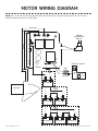
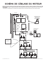
MOTOR WIRING DIAGRAM
NOTE: This is a universal, multi-voltage diagram. Double-check your motor's voltage for proper connections. Over-Current
Protection Devices not shown in this illustration.
12v
24v
36v
BLACK M-
RED M+
RED B+
MOTOR
SPEED
ADJUSTMENT
SWITCH
BATTERY GAUGE
RED
12V BATT 1
12V BATT 1 12V BATT 2
12V BATT 1 12V BATT 2 12V BATT 3
BLACK
BLACK B-

STOWING AND DEPLOYING THE MOTOR
WARNING:
When raising or lowering the motor, keep fi ngers clear of all hinge and pivot points and all moving parts.
MOUNT FEATURES
• The motor mount is designed to fold back and lock the motor fl at on the deck when not in use and to
provide secure stowage for transport.
• The pull grip and rope releases the lock bar, which automatically engages when the unit is lowered or
raised into position. The pull grip and rope should be used to both lower and raise the unit.
• The motor rest positions the lower unit as it comes in contact with the nose of the mount and guides
it onto the motor rest.
• The yoke captures the motor shaft and keeps the lower unit centered on the motor rest.
• The hold-down strap must be used to place pressure on the motor shaft to hold the lower unit
tightly against the motor rest when stowed.
• The pull grip and rope can be stored by placing the pull grip into the rope stow slot on the control box of the motor.
TO DEPLOY THE MOTOR
Simply pull back and lift the motor off of the mount with the pull grip and rope. Lower the motor into the water using the pull grip
and rope. The motor will lock into the deployed position automatically.
TO STOW THE MOTOR
Pull back and lift the motor out of the water with the pull grip and rope. Lower the motor lower unit onto the motor rest using the
pull grip and rope. The motor will lock into the stowed position automatically. Wrap the hold-down strap over top of the motor
shaft to secure the motor.
Motor Rest
Lower Unit
Motor Shaft
Pull Grip and Rope
Hold Down Strap
minnkotamotors.com | 13
©2015 Johnson Outdoors Marine Electronics, Inc.
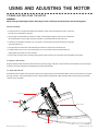
USING AND ADJUSTING THE MOTOR

Depth Adjustment Knob
Outer Shaft
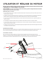
ADJUSTING THE DEPTH OF THE MOTOR
When setting the depth be sure the top of the motor is submerged at least 12” to
avoid churning or agitation of surface water. The propeller must be completely
submerged.
1. Firmly grasp the motor shaft and hold it steady.
2. Loosen steering tension knob.
3. Open the lever arm to loosen the Quick Release Depth Collar.
4. Vertically adjust the height of the motor to the desired position.
5. Bring the depth collar to the top of the steering tension knob, and close the
lever arm to lock the depth collar into position.
6. Tighten the steering tension knob to achieve the desired steering resistance.
NOTE: The tension of the quick release depth collar can be adjusted with a screw
driver to obtain the proper feel.
CAUTION:
• Never operate your motor when it is out of the water.
• Over-tightening the clamp screws can damage the bracket.
ADJUSTING THE STEERING
• Adjust the steering tension knob to provide enough tension to allow the motor to turn freely, yet remain in any position without
being held
OR
• Tighten the knob to place the motor in a preset position to leave your hands free for fi shing.
Quick Release
Depth Collar
Steering Tension
Vertical Stow Knob
12” Minimum
Depth
Lever Arm
ADJUSTING THE DEPTH OF THE MOTOR
When setting the depth be sure the top of the motor is submerged at least 12” to
avoid churning or agitation of surface water. The propeller must be completely
submerged.
1. Firmly grasp the motor shaft and hold it steady.
2. Loosen steering tension knob.
3. Open the lever arm to loosen the Quick Release Depth Collar.
4. Vertically adjust the height of the motor to the desired position.
5. Bring the depth collar to the top of the steering tension knob, and close the
lever arm to lock the depth collar into position.
6. Tighten the steering tension knob to achieve the desired steering resistance.
NOTE: The tension of the quick release depth collar can be adjusted with a screw
driver to obtain the proper feel.
CAUTION:
• Never operate your motor when it is out of the water.
• Over-tightening the clamp screws can damage the bracket.
ADJUSTING THE STEERING
•
Adjust the steering tension knob to provide enough tension to allow the motor to turn freely, yet remain in any position without
being held
OR
• Tighten the knob to place the motor in a preset position to leave your hands free for fi shing.
Quick Release
Depth Collar
Steering Tension
Vertical Stow Knob
12” Minimum
Depth
Lever Arm
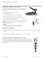
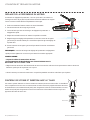
CONTROLLING SPEED & STEERING WITH THE TILLER
This motor off ers variable forward and reverse speeds. The speed control may be operated in either
direction, forward or reverse. Turn the tiller handle counterclockwise from (OFF) to increase reverse
speed and clockwise from (OFF) to increase forward speed. Speed decreases as you approach (OFF)
from either direction.
Forward
Reverse
12” Minimum
Depth
14 | minnkotamotors.com
©2015 Johnson Outdoors Marine Electronics, Inc.
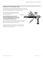
USING & ADJUSTING THE MOTOR

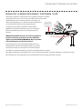
ADJUSTING THE TILT/EXTEND TILLER
Your trolling motor features 7 usable handle tilt positions: 45°, 30°, and 15° up and
down from the 0° (horizontal) position. To use the down positions, you must fi rst press
the release button located on the left underside of the pivot handle.
Your trolling motor handle also features a unique stow
position, that is useful for limiting the amount of space
required for storage or travel.
Important: BEFORE attempting to put the
handle in the stowed position, the speed selector
must be in the OFF/STOW position . Failure to do
so will damage the internal mechanism.
First press the release button located on the left underside of the pivot handle,
then push the handle down until you feel the handle “lock in” to the stowed
position. This will be almost parallel to the motor shaft.
To extend the handle, pull the handle towards you to the desired position.
The handle will extend a full 6 inches. To retract, push the handle in until it
meets the face of the motor control head.
Handle Controls:
Off /On, Steering, and
Forward/Reverse
Release Button
minnkotamotors.com | 15
©2015 Johnson Outdoors Marine Electronics, Inc.
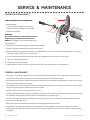
USING & ADJUSTING THE MOTOR

Propeller
Drive Pin
Anode/Nut
Washer
PROPELLER REPLACEMENT
TOOLS AND RESOURCES REQUIRED:
• Box End Wrench
- 1/2” for motors with 70 lbs thrust or lower.
- 9/16” for motors with 80 lbs thrust or higher.
• Screwdriver (optional)
CAUTION:
Disconnect the motor from the battery before
beginning any prop work or maintenance.
NOTE: The propeller on your motor may diff er from
the one pictured.
1. Disconnect motor from battery prior to changing the propeller.
2. Hold the propeller and loosen the anode/nut with a wrench.
3. Remove anode/nut and washer. If the drive pin is sheared/broken, you will need to hold the shaft steady with a screwdriver
blade pressed into the slot on the end of the shaft.
4. Turn the old prop to horizontal (as illustrated) and pull it straight off . If drive pin falls out, push it back in.
5. Align new propeller with drive pin.
6. Install prop washer and anode/nut.
7. Tighten anode/ nut 1/4 turn past snug. [25-35 inch lbs.] Be careful, over tightening can damage prop.
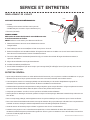
GENERAL MAINTENANCE
• After every use, the entire motor should be rinsed with freshwater, then wiped down with a cloth dampened with an aqueous
based silicone spray. Do not spray water into the ventilation openings in the head of the motor.
• The composite shaft requires periodic cleaning and lubrication for proper retraction and deployment. A coating of an aqueous
based silicone spray will improve operation.
• The propeller must be inspected and cleaned of weeds and fi shing line after every use. Fishing line and weeds can get behind
the prop, damage the seals and allow water to enter the motor.
• Verify the prop nut is secure each time the motor is used.
• To prevent accidental damage during transportation or storage, disconnect the battery whenever the motor is off of the water.
For prolonged storage, lightly coat all metal parts with an aqueous based silicone spray.
• For maximum battery life, recharge the battery(s) as soon as possible after use. For maximum motor performance, restore
battery to full charge prior to use.
• Keep battery terminals clean with fi ne sandpaper or emery cloth (fl ooded lead acid only).
• The propeller is designed to provide optimum operation with very high effi ciency. To maintain this top performance, the
leading edge of the blades must be kept smooth. If they are rough or nicked from use, restore to smooth by sanding with fi ne
sandpaper.
16 | minnkotamotors.com
©2015 Johnson Outdoors Marine Electronics, Inc.
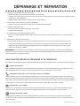
SERVICE & MAINTENANCE

1. Motor fails to run or lacks power:
• Check battery connections for proper polarity.
• Make sure terminals are clean and corrosion free. Use fi ne sandpaper or emery cloth to clean terminals.
• Check battery water level. Add water if needed.
2. Motor loses power after a short running time:
• Check battery charge. If low, restore to full charge.
3. Motor is diffi cult to steer:
• Loosen the steering tension knob on the bracket
• Lubricate the composite shaft.
4. You experience prop vibration during normal operation:
• Remove and rotate the prop 180°. See removal instructions in the Propeller Replacement section.
5. Experiencing interference with your fi shfi nder:
• You may, in some applications, experience interference in your depth fi nder display. We recommend that you use a seperate
deep cycle marine battery for your trolling motor and that you power the depth fi nder from the starting/cranking battery. If
problems still persist, call our service department at 1-800-227-6433.
NOTE: For all other malfunctions, visit an Authorized Service Center. You can search for an Authorized Service Center in your
area by visiting our Authorized Service Center page, found online at minnkotamotors.com, or by calling our customer service
number, 800-227-6433.
FOR FURTHER TROUBLESHOOTING AND REPAIR
We off er several options to help you troubleshoot and/or repair your product. Please read through the options listed below.
FREQUENTLY ASKED QUESTIONS
We have FAQs available on our website to help answer all of your Minn Kota questions. Visit minnkotamotors.com and click on
“Frequently Asked Questions” to fi nd an answer to your question.
CALL US (FOR U.S. AND CANADA)
Our consumer service representatives are available Monday – Friday between 7:00 a.m. – 4:30 p.m. CST at 800-227-6433.
If you are calling to order parts, please have the 11-character serial number from your product, specifi c part numbers, and credit
card information available. This will help expedite your call and allow us to provide you with the best consumer service possible.
You can reference the parts list located in your manual to identify the specifi c part numbers.
EMAIL US
You can email our consumer service department with questions regarding your Minn Kota products. To email your question, visit
minnkotamotors.com and click on “Support”.
AUTHORIZED SERVICE CENTERS
Minn Kota has over 300 authorized service centers in the United States and Canada where you can purchase parts or get your
products repaired. Please visit our Authorized Service Center page on our website to locate a service center in your area.
minnkotamotors.com | 17
©2015 Johnson Outdoors Marine Electronics, Inc.
TROUBLESHOOTING & REPAIR

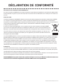
ENVIRONMENTAL COMPLIANCE STATEMENT:
It is the intention of JOME to be a responsible corporate citizen, operating in compliance with known and applicable
environmental regulations, and a good neighbor in the communities where we make or sell our products.
WEEE DIRECTIVE:
EU Directive 2002/96/EC “Waste of Electrical and Electronic Equipment Directive (WEEE)” impacts most distributors, sellers,
and manufacturers of consumer electronics in the European Union. The WEEE Directive requires the producer of consumer
electronics to take responsibility for the management of waste from their products to achieve environmentally responsible
disposal during the product life cycle.
WEEE compliance may not be required in your location for electrical & electronic equipment (EEE), nor may it be required
for EEE designed and intended as fi xed or temporary installation in transportation vehicles such as
automobiles, aircraft, and boats. In some European Union member states, these vehicles are considered
outside of the scope of the Directive, and EEE for those applications can be considered excluded from the
WEEE Directive requirement.
This symbol (WEEE wheelie bin) on product indicates the product must not be disposed of with other
household refuse. It must be disposed of and collected for recycling and recovery of waste EEE. Johnson
Outdoors Inc. will mark all EEE products in accordance with the WEEE Directive. It is our goal to comply
in the collection, treatment, recovery, and environmentally sound disposal of those products; however, these requirement do
vary within European Union member states. For more information about where you should dispose of your waste equipment for
recycling and recovery and/or your European Union member state requirements, please contact your dealer or distributor from
which your product was purchased.
DISPOSAL:
Minn Kota motors are not subject to the disposal regulations EAG-VO (electric devices directive) that implements the WEEE
directive. Nevertheless never dispose of your Minn Kota motor in a garbage bin but at the proper place of collection of your local
town council.
Never dispose of battery in a garbage bin. Comply with the disposal directions of the manufacturer or his representative and
dispose of them at the proper place of collection of your local town council.
WARNING: This product contains chemicals known to the State of California to cause cancer and birth defects
or other reproductive harm.
18 | minnkotamotors.com
©2015 Johnson Outdoors Marine Electronics, Inc.
COMPLIANCE STATEMENTS

Part #2284914 Rev D 11/15ECN 36894
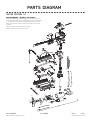
This page provides Minn Kota® WEEE compliance disassembly instructions.
For more information about where you should dispose of your waste equipment
for recycling and recovery and/or your European Union member state require-
ments, please contact your dealer or distributor from which your product was
purchased.
Tools required, but not limited to: fl at head screw driver,
Phillips screw driver, socket set, pliers, wire cutters.
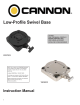
RIPTIDE FORTREX 112
112 LBS THRUST - 36 VOLT - 62” SHAFT
425
260
255
220
225
235
215
230
420
240
200
205
210
400
395
265
410
390
360
365
370
375
380
385
250
245
415
405
208
700
720
721
980
710
815
725
730
735
740
745
750
760
765
810
830
835
820
825
845
860
865
870
875
880
940
975
885
890
910
920
915
925
935
930
932
905
900
895
770
775
780
785
790
795
800
850
855
515
520
525
535
530
540
550
555
560
570
500
510
565
136
310
135
715
737
545
796
752
751
753
710
871
776
30
31
70
120
115
10
80
90
5
1
15
95
100
71
35
25
50
65
60
85
20
40
1010
1015
1020
110
137
41
1000
minnkotamotors.com | 19
©2015 Johnson Outdoors Marine Electronics, Inc.
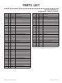
PARTS DIAGRAM

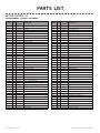
RIPTIDE FORTREX 112
112 LBS THRUST - 36 VOLT - 62” SHAFT
ITEM QTY
PART
NUMBER
DESCRIPTION
1 1 2317091 36V MOTOR 62” SW
5 1 2-100-245 ARMATURE ASSEMBLY
10 1 140-014 BEARING
15 1 788-040 RETAINING RING
20 1 2-200-340 CENTER HOUSING ASSEMBLY
25 1 2-300-151 BRUSH END HOUSING ASSEMBLY
30 1 421-241 PLAIN END HOUSING ASSY. STD
31 1 582-016 RETAINING CLIP
35 1 144-017 FLANGE BEARING
40 2 880-025 SEAL
41 1 725-095 PAPER TUBE - SEAL BORE
50 2 188-095 BRUSH
60 1 9-738-011 BRUSH PLATE ASSEMBLY
65 2 975-045 BRUSH SPRING
2881450 SEAL AND O-RING KIT [40, 70-80]
70 1 701-098 O-RING, PLAIN END HOUSING
71 1 701-107 O-RING, BRUSH END HOUSING
80 2 701-009 O-RING, THRU-BOLT
85 2 2053410 SCREW-BRUSH PLATE
90 2 830-094 THRU-BOLT
95 1 990-051 WASHER, STEEL
100 2 990-052 WASHER, NYLATRON
110 1 2307312 FERRITE BEAD
115 1 990-011 WASHER, SHIM
120 2 992-011 WASHER, BELLEVILLE
135 1 640-045 LEADWIRE, BLACK 62”
136 1 640-145 LEADWIRE, RED 62”
200 1 2285605 DECAL, C-BOX COVER 112#
205 1 2060296 C-BOX COVER
208 2 2325666 DECAL - MINNKOTA
210 1 2074082 BATTERY METER, 36V SW
215 2 3043427 SCREW, #8 X 7/8 SS
220 1 2184017 CONTROL BOARD, 24/36V
2888411 POTENTIOMETER REPLACEMENT KIT
225 2 2303434 SCREW, #8-30 X 5/8 SS
230 1 2062503 CONTROL BOX, VARS, SW
235 1 2062905 STRAIN RELIEF
240 6 2303412 SCREW, #6 X 5/8 SS
245 2 2263434 SCREW, #8 X 1 SS
250 1 2263406 SCREW, #10-24 X 2 SS
255 1 2061517 COLLAR, C-BOX
ITEM QTY
PART
NUMBER
DESCRIPTION
260 1 2333101 NUT, 10-24, NYLOCK, SS
265 1 2991521 CAM LOCK/DEPTH COLLAR ASSY
310 1 2002015 TUBE COMPOSITE 62”
1 2990957 HANDLE ASSY, VARS [360-410]
360 1 2990456 GRIP ASSY, VARS [360-375]
365 2 2060015 BEARING, HANDLE
370 1 2063405 SCREW, #6 PFH SS
375 1 2884092 YOKE / SPIDER ASSY, VARS
380 1 2302742 SPRING, DETENT, OFF
385 2 2060005 BEARING, HANDLE PIVOT
390 1 2060900 HANDLE PIVOT, TOP
395 1 2302745 SPRING, RELEASE BUTTON
400 1 2063700 BUTTON, RELEASE
405 1 2060905 HANDLE PIVOT, BOTTOM
410 6 2303412 SCREW, #6 X 5/8 SS
415 1 2062715 SPRING, HANDLE PIVOT
420 1 2061700 WASHER, POT HOLDER
425 1 2992521 LEADWIRE ASSY
1 2991757 BOWGUARD ASSY SW [500-570]
500 1 2283414 SCREW, 5/16-18 SHCS, RIE
510 1 2281700 WASHER, 5/16 HIGHCOLLAR LOCK
515 1 2281953 BOWGUARD TOP
520 1 2280001 BEARING, BOWGUARD TOP
525 1 2011366 KNOB, SS
530 1 2261525 SPRING SLEEVE, UPPER
535 1 2264702 TUBE INSERT, UPPER
540 1 2262705 SPRING, BOWGUARD
545 1 2282000 TUBE INSERT, LOWER
550 1 2281525 SPACER, LOWER SPRING
555 1 2281520 SPRING SLEEVE, LOWER
560 1 2991729 BOWGUARD BOTTOM
565 2 2282612 PIN-SPRING, 5/16”, SS
570 3 2283413 SCREW, 3/8-16 SHCS, RIE
1 2991751 MOUNT, FORTREX, 62” [700-940]
700 1 2280800 LINK, BOWGUARD MOUNT, LEFT
710 2 2287303 BUSHING, UPPER PINS
715 4 2283411 SCREW, 1/4-20 X 1” FHS RIE TORX
720 1 2880400 PULL GRIP ASSEMBLY
721 2 2261732 WASHER
725 1 2771601 ROPE ASSEMBLY
730 1 2281516 SPACER, INNER ARM
20 | minnkotamotors.com
©2015 Johnson Outdoors Marine Electronics, Inc.
PARTS LIST
La page est en cours de chargement...
La page est en cours de chargement...
La page est en cours de chargement...
La page est en cours de chargement...
La page est en cours de chargement...
La page est en cours de chargement...
La page est en cours de chargement...
La page est en cours de chargement...
La page est en cours de chargement...
La page est en cours de chargement...
La page est en cours de chargement...
La page est en cours de chargement...
La page est en cours de chargement...
La page est en cours de chargement...
La page est en cours de chargement...
La page est en cours de chargement...
La page est en cours de chargement...
La page est en cours de chargement...
La page est en cours de chargement...
La page est en cours de chargement...
La page est en cours de chargement...
La page est en cours de chargement...
-
 1
1
-
 2
2
-
 3
3
-
 4
4
-
 5
5
-
 6
6
-
 7
7
-
 8
8
-
 9
9
-
 10
10
-
 11
11
-
 12
12
-
 13
13
-
 14
14
-
 15
15
-
 16
16
-
 17
17
-
 18
18
-
 19
19
-
 20
20
-
 21
21
-
 22
22
-
 23
23
-
 24
24
-
 25
25
-
 26
26
-
 27
27
-
 28
28
-
 29
29
-
 30
30
-
 31
31
-
 32
32
-
 33
33
-
 34
34
-
 35
35
-
 36
36
-
 37
37
-
 38
38
-
 39
39
-
 40
40
-
 41
41
-
 42
42


MINN KOTA Riptide Manuel utilisateur
- Taper
- Manuel utilisateur
- Ce manuel convient également à
dans d''autres langues
- English: MINN KOTA Riptide User manual
Documents connexes
-
MINN KOTA CAMO Manuel utilisateur
-
MINN KOTA POWERDRIVE V2 Manuel utilisateur
-
-
MINN KOTA MINN-KOTA 1363885 EO Transom Mount Electric Outboard Motor Manuel utilisateur
-
-
-
-
-
-
Autres documents
-
Greenworks 9000107 Manuel utilisateur
-
 Johnson Outdoors 1820089 Guide d'installation
-
Garmin Force Trolling Motor Freshwater 57 Guide d'installation
-
Talon 1810225 Manuel utilisateur
-
Intermec 6820 Guide de démarrage rapide
-
MINA KOTA 2207105 Manuel utilisateur
-
Cannon 2450163 Manuel utilisateur
-
Akron 3578 STREAMMASTER Installation, Operating And Maintenance Instructions
-
 OCANNON 1903002 Low-Profile Swivel Base Manuel utilisateur
-
Cannon UNI-TROLL 5 ST Manuel utilisateur

