
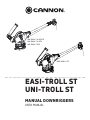
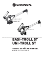
EASI-TROLL ST
UNI-TROLL ST
MANUAL DOWNRIGGERS
USER MANUAL
UNI-TROLL™ 10 STX-TS
UNI-TROLL™ 10 STX
UNI-TROLL™ 5 ST
EASI-TROLL™ ST

Model: ______________________________________________________________________
Serial Number: ________________________________________________________________
Purchase Date: ________________________________________________________________
Store Where Purchased: __________________________________________________________
Please thoroughly read this user manual. Follow all instructions and heed all safety and cautionary notices below. Use of this downrigger is only
permitted for persons that have read and understood these user instructions. Minors may use this product only under adult supervision.
ATTENTION: Your Cannon downnrigger should only be used for its intended purpose. Improper use will void the warranty and may be a safety risk.
CAUTION: Persons whose ability to run the downrigger or whose reactions are impaired by alcohol, drugs, medication, or other substances are not
permitted to use this product.
THANK YOU
Thank you for purchasing a Cannon downrigger. We have designed your new downrigger to be an accurate and reliable
tool that will enhance fi shing control and improve your ability to catch fi sh. We hope that you enjoy the use of your
new downrigger and enjoy the benefi t of controlled depth fi shing for years to come by always following safe boating
practices and laws wherever you are fi shing.
This manual covers installation and the operation of your downrigger. Read this manual carefully before operating your
new Cannon downrigger. Retain this manual for future reference.
REMEMBER TO KEEP YOUR RECEIPT AND IMMEDIATELY REGISTER YOUR DOWNRIGGER.
To receive all the benefi ts for your product warranty, please fi ll out and mail the enclosed registration card. You may
also complete registration on our website at cannondownriggers.com.
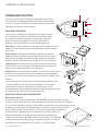
LOCATING YOUR SERIAL NUMBER
Your Cannon 11-character serial number is very important. It helps to determine the specifi c model and year of manufacture. When contacting
Consumer Service or registering your product, you will need to know your product’s serial number. We recommend that you write the serial number
down in the space provided below so that you have it available for future reference.
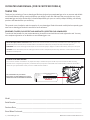
CE MASTER USER MANUAL (FOR CE CERTIFIED MODELS)
The serial number on your Cannon
Easi-Troll or Uni-Troll downrigger is located
towards the inside of the bottom of the frame.
Made by Cannon
Johnson Outdoors
Marine Electronics, Inc.
121 Power Drive
Mankato, MN 56001 USA
Downriggers
Produced in 2015
EASI-TROLL ST MANUAL DOWNRIGGER
MODEL 1901020
SER NO K365 CN12345
2 | cannondownriggers.com
©2015 Johnson Outdoors Marine Electronics, Inc.
EXAMPLE

cannondownriggers.com | 3
©2015 Johnson Outdoors Marine Electronics, Inc.
TABLE OF CONTENTS
Warranty / Service Information 4
Assembly & Installation 6-10
Features 5
Mounting 6-7
Installing the Boom 7
Installing the End Pulley 8
Adjusting the Boom Length (UniTroll 10 Models Only) 8
Attaching the Crank Handle Assembly 8
Attaching the Rod Holder 9
Terminating the Downrigger Cable 10
Attaching the Line Release 10
Operating the Downrigger 11
BlowBack Calculations 12
Service & Repair 13
Parts Diagram 14
Parts List 15
WEEE Compliance 16
Notes 17

CANNON LIMITED WARRANTY
Johnson Outdoors Marine Electronics, Inc. (“JOME”) extends the following limited warranty to the original retail purchaser only. Warranty coverage is not
transferable.
CANNON® LIMITED LIFETIME WARRANTY
JOME warrants to the original purchaser that if the accompanying product (see exclusions below) proves to be defective in material or workmanship within the
following warranty periods, JOME will, at its option, either repair or replace same without charge (but no cash refunds will be made):
The boom, motor (if applicable), and reels, plus all plastic parts, including but not limited to frames and bases, will be free from defects in materials and
workmanship, subject to normal wear and tear, for the original purchaser’s lifetime.
All other items will have 1-year limited warranties from the date of original retail purchase, except THE FOLLOWING ITEMS THAT HAVE NO WARRANTY:
swivel lock pin, weights, and wire cable.
LIMITATION AND EXCLUSION OF IMPLIED WARRANTIES AND CERTAIN DAMAGES
THERE ARE NO EXPRESS WARRANTIES OTHER THAN THESE LIMITED WARRANTIES. JOME DISCLAIMS LIABILITY FOR INCIDENTAL AND CONSEQUENTIAL
DAMAGES, AND IN NO EVENT SHALL ANY IMPLIED WARRANTIES (EXCEPT ON THE BOOM, MOTOR, REELS, AND ALL PLASTIC PARTS), INCLUDING ANY
IMPLIED WARRANTY OF MERCHANTABILITY OR FITNESS FOR PARTICULAR PURPOSE, EXTEND BEYOND ONE YEAR FROM THE DATE OF PURCHASE
(AND IN THE CASE OF THE SWIVEL LOCK PIN, WEIGHTS, AND WIRE CABLE, JOME DISCLAIMS ALL IMPLIED WARRANTIES). THIS WRITING CONSTITUTES
THE ENTIRE AGREEMENT OF THE PARTIES WITH RESPECT TO THE SUBJECT MATTER HEREOF; NO WAIVER OR AMENDMENT SHALL BE VALID UNLESS
IN WRITING SIGNED BY JOME.
Some states do not allow limitations on how long an implied warranty lasts or the exclusion or limitation of consequential damages, so the above limitation or
exclusion may not apply to you. This warranty gives you specifi c legal rights, and you may also have other rights that vary from state to state.
CANNON® SERVICE POLICY
AFTER THE APPLICABLE WARRANTY PERIOD
After the applicable warranty period, or, if one of the above exclusions applies, Cannon® products will be repaired for a charge of parts plus labor. All factory
repairs, after the applicable warranty period, carry a 90-Day Limited Warranty, subject to the exclusions and limitations stated above.
TO ENFORCE WARRANTY OR TO OBTAIN REPAIRS AFTER WARRANTY
To obtain warranty service in the U.S., the downrigger believed to be defective and the proof of original purchase (including the date of purchase) must be
presented to a Cannon® Authorized Service Center or to Cannon®’s factory service center in Mankato, MN. Except as noted below, any charges incurred for
service calls, transportation or shipping/freight to/from the Cannon® Authorized Service Center or Cannon®’s factory, labor to haul out, remove, re-install
or re-rig products for warranty service, or any similar items are the sole and exclusive responsibility of the purchaser. Warranty service can be arranged by
contacting a Cannon® Authorized Service Center or by contacting the factory at 1-800-227-6433 or by email to [email protected]. If the
necessary repairs are covered by the warranty, we will pay the return shipping charges to any destination within the United States. Downriggers purchased
outside of the U.S. (or parts of such downriggers) must be returned prepaid with proof of purchase (including the date of purchase and serial number) to any
Authorized Cannon® Service Center in the country of purchase.
NOTE: Do not return your Cannon® downrigger or parts to your retailer. Your retailer is not authorized to repair or replace them.
Major parts, such as the motor and main frame, must be returned to JOME in Mankato, Minnesota, or a Cannon® Authorized Service Center, for repair or
replacement. To reduce shipping costs, we suggest removal of loose parts such as the boom and rod holders. Small parts that can be easily removed such as
the handle and/or the counter, may be removed from the downrigger and returned for repair or replacement. Retain your sales receipt. Proof of purchase
must accompany product when returned.
Return Address:
Johnson Outdoors Marine Electronics, Inc.
Attn: Cannon Service Dept.
121 Power Drive
Mankato, MN 56001
4 | cannondownriggers.com
©2015 Johnson Outdoors Marine Electronics, Inc.
LIMITED WARRANTY

CANNON LIMITED WARRANTY
Johnson Outdoors Marine Electronics, Inc. (“JOME”) extends the following limited warranty to the original retail purchaser only. Warranty coverage is not
transferable.
CANNON® LIMITED LIFETIME WARRANTY
JOME warrants to the original purchaser that if the accompanying product (see exclusions below) proves to be defective in material or workmanship within the
following warranty periods, JOME will, at its option, either repair or replace same without charge (but no cash refunds will be made):
The boom, motor (if applicable), and reels, plus all plastic parts, including but not limited to frames and bases, will be free from defects in materials and
workmanship, subject to normal wear and tear, for the original purchaser’s lifetime.
All other items will have 1-year limited warranties from the date of original retail purchase, except THE FOLLOWING ITEMS THAT HAVE NO WARRANTY:
swivel lock pin, weights, and wire cable.
LIMITATION AND EXCLUSION OF IMPLIED WARRANTIES AND CERTAIN DAMAGES
THERE ARE NO EXPRESS WARRANTIES OTHER THAN THESE LIMITED WARRANTIES. JOME DISCLAIMS LIABILITY FOR INCIDENTAL AND CONSEQUENTIAL
DAMAGES, AND IN NO EVENT SHALL ANY IMPLIED WARRANTIES (EXCEPT ON THE BOOM, MOTOR, REELS, AND ALL PLASTIC PARTS), INCLUDING ANY
IMPLIED WARRANTY OF MERCHANTABILITY OR FITNESS FOR PARTICULAR PURPOSE, EXTEND BEYOND ONE YEAR FROM THE DATE OF PURCHASE
(AND IN THE CASE OF THE SWIVEL LOCK PIN, WEIGHTS, AND WIRE CABLE, JOME DISCLAIMS ALL IMPLIED WARRANTIES). THIS WRITING CONSTITUTES
THE ENTIRE AGREEMENT OF THE PARTIES WITH RESPECT TO THE SUBJECT MATTER HEREOF; NO WAIVER OR AMENDMENT SHALL BE VALID UNLESS
IN WRITING SIGNED BY JOME.
Some states do not allow limitations on how long an implied warranty lasts or the exclusion or limitation of consequential damages, so the above limitation or
exclusion may not apply to you. This warranty gives you specifi c legal rights, and you may also have other rights that vary from state to state.
CANNON® SERVICE POLICY
AFTER THE APPLICABLE WARRANTY PERIOD
After the applicable warranty period, or, if one of the above exclusions applies, Cannon® products will be repaired for a charge of parts plus labor. All factory
repairs, after the applicable warranty period, carry a 90-Day Limited Warranty, subject to the exclusions and limitations stated above.
TO ENFORCE WARRANTY OR TO OBTAIN REPAIRS AFTER WARRANTY
To obtain warranty service in the U.S., the downrigger believed to be defective and the proof of original purchase (including the date of purchase) must be
presented to a Cannon® Authorized Service Center or to Cannon®’s factory service center in Mankato, MN. Except as noted below, any charges incurred for
service calls, transportation or shipping/freight to/from the Cannon® Authorized Service Center or Cannon®’s factory, labor to haul out, remove, re-install
or re-rig products for warranty service, or any similar items are the sole and exclusive responsibility of the purchaser. Warranty service can be arranged by
contacting a Cannon® Authorized Service Center or by contacting the factory at 1-800-227-6433 or by email to [email protected]. If the
necessary repairs are covered by the warranty, we will pay the return shipping charges to any destination within the United States. Downriggers purchased
outside of the U.S. (or parts of such downriggers) must be returned prepaid with proof of purchase (including the date of purchase and serial number) to any
Authorized Cannon® Service Center in the country of purchase.
NOTE: Do not return your Cannon® downrigger or parts to your retailer. Your retailer is not authorized to repair or replace them.
Major parts, such as the motor and main frame, must be returned to JOME in Mankato, Minnesota, or a Cannon® Authorized Service Center, for repair or
replacement. To reduce shipping costs, we suggest removal of loose parts such as the boom and rod holders. Small parts that can be easily removed such as
the handle and/or the counter, may be removed from the downrigger and returned for repair or replacement. Retain your sales receipt. Proof of purchase
must accompany product when returned.
Return Address:
Johnson Outdoors Marine Electronics, Inc.
Attn: Cannon Service Dept.
121 Power Drive
Mankato, MN 56001
cannondownriggers.com | 5
©2015 Johnson Outdoors Marine Electronics, Inc.
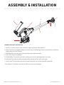
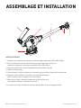
ASSEMBLY & INSTALLATION
1
2
3
4
6
5
7
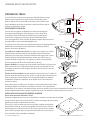
DOWNRIGGER PARTS DESCRIPTION
1. Reel: This is used to spool the cable, available in lengths ranging from 150 to 400 feet.
2. Boom: This is used to extend the weight out from the body of the downrigger and has a pulley fixed to its end. Boom
lengths range from 24 to 53 inches.
3. Swivel Head: This relays the cable at the end of the boom to lower the weight.
4. Cable: This connects to the weight.
5. Mounting Base: This attaches to the boat, enabling you to place the downrigger where you choose.
6. Rod Holder: This holds your fishing rods while trolling and may also be used for storing rods.
7. Boom Clamps: These lock the boom sections together after the boom has been extended or retracted.*
* This diagram is for reference only and may differ from your actual downrigger.

DOWNRIGGER MOUNTING
Choosing a good location to mount your downrigger on your boat is
very important. A downrigger should be mounted in a location where
it is easy to observe your fi shing rod and react quickly to operate the
downrigger once there is a fi sh on the line.
INSTALLING THE INCLUDED MOUNTING BASE
Decks thinner than 1/4”
Use a Cannon deck plate (sold separately - PN 2200693) to prevent defl ection and add
stability to decks thinner than 1/4”. Use the deck plate as a template to mark the hole locations.
If access to the underside of the deck is not available, the deck plate can be mounted using screws
and wellnuts (not included). Use the deck plate as a template to mark locations and drill 4
wellnut clearance holes. Use four 1/4-20 x 1-1/2” fl at head screws and four wellnuts to
mount deck plate. Tighten the screws so the wellnuts are fi rmly compressed.
Where the underside is accessible, the deck plate can be mounted using
screws, nuts, and washers. Drill 9/32” holes. Use four 1/4-20 x 1-1/2” fl at head
screws, nuts and washers (fl at and lock). Fasten plate to deck. To secure the
mounting base to the deckplate use four 1/4-20 x 1” truss head screws.
Typical Mounting Positions
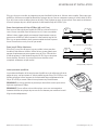
MOUNTING ACCESSORIES
Cannon offers a complete line of mounting accessories that allow
you to optimize your spread to fi t the way you fi sh. Before making
any permanent changes to your boat, consider what accessories
might be used in your application. To see the complete line of
mounting accessories available, visit cannondownriggers.com.
Deck Plates are necessary when extra strength must be added to the base
material of the boat and for attaching the downrigger to other mounting
accessories.
Gimbal Mounts are designed to fi t medium-sized fl ush mounted rod
holders built into the gunwale of many larger fi shing boats and cruisers.
Only sturdy, high quality rod holders should be used for this temporary
mounting system. Gimbal mounts are available in 9” or 12” post lengths.
Clamp Mounts can be mounted at the junction of two rail sections with
the aid of two ¼” pieces of plywood. They will protect your rail from any
marks from the clamp and provide a non-slip surface.
Side/Rail mounts can be mounted to a welded T-section. It can also be used
at the two rail section butt joint. In both installations it is recommended to
use a non-slip material, such as rubber or a thin wood sheet, between metal
surfaces.
You can also use these for mounting to a very narrow side gunwale. There
is a plate provided for back-up with bolts and washers. If the gunwale
compartment is foamed in, then wellnuts should be used. It is also
recommended to install two additional fl at head screws through the top plate
for stabilization (you will need to drill and countersink).
Deckplate
Gimbal Mount
Clamp Mount
Side Rail Mount
on T-Section
Side Rail Mount
on Gunwhale
6 | cannondownriggers.com
©2015 Johnson Outdoors Marine Electronics, Inc.
ASSEMBLY & INSTALLATION

Decks from 1/4” to 7/16” thick
Where access to the underside of the deck is not available, the mounting
base can be attached to the deck using wellnuts. Use the base as a
template to mark locations and drill four wellnut clearance holes. Mount
the base using four 1/4-20 x 1-1/2” truss head screws and four wellnuts.
Tighten the screws so the wellnuts are fi rmly compressed as pictured.
Decks thicker than 7/16”
For decks thicker than 7/16”, or where the underside of the deck is
accessible, mount the base with screws, nuts, and washers. Use the
base as a template to mark the locations and drill four 9/32” holes. Use
four 1/4-20 x 2” truss head screws and four each fl at washers and nuts.
Fasten the base to the deck as pictured.
NOTE: Wellnuts SHOULD NOT be used on decks thicker than 7/16”.
NOTE: When using the telescopic boom, we strongly recommend the
use of a deck plate on all boats to provide adequate stability for the
downrigger.
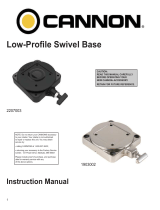
Low-Profi le Swivel Base
To mount the Low-Profi le Swivel Base, follow the same procedure as for the deck
plate with this exception: use four 1/4”-20 x 1-1/2” truss head screws to fasten the
mounting base and four additional 1/4”-20” x 2-1/2” truss head screws to attach the
swivel base tothe boat deck.
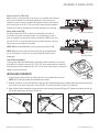
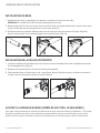
INSTALLING THE BOOM
1. Insert boom into frame (Figure 1) and line up holes in boom with holes in frame.
NOTE: Easi-Troll units require the included boom adapter.
2. Remove 1/4-20 x 2” bolt and 1/4-20 nylon locknut from included hardware bag assembly and insert the locknut into the
hex pocket on the nose of the frame. Insert 1/4-20 x 2” bolt into reel side of frame nose. (Figure 2)
3. With a Phillips head screw driver, thread bolt into nylon locknut from step 2 (Figure 2). Tighten bolt until the end of the
bolt is fl ush with the top of the nut. (Figure 3)
Decks from 1/4” to 7/16” Thick
Decks Thicker Than 7/16”
Figure 2
Figure 3Figure 1
Low-Profi le Swivel Base
cannondownriggers.com | 7
©2015 Johnson Outdoors Marine Electronics, Inc.
ASSEMBLY & INSTALLATION
Wellnut
Base
Deck
1/4-20” screw
Washer & Nut
Base
Deck
1/4-20” screw

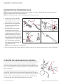
INSTALLING THE END PULLEY
1. Locate boom end assembly and then insert boom end post into end of the small tube of the boom assembly. (Figure 4)
2. Align hole in boom post with hole in small end tube.
3. Secure boom end with #8 screw as shown. Tighten with Phillips head screw driver by turning screw clockwise until tight.
(Figure 5)
ADJUSTING THE BOOM LENGTH (UNI-TROLL 10 MODELS ONLY)
To adjust the boom length (with the boom extending away from you) rotate the boom clamps (See item # 7 on page 5)
approximately ¼ turn counter-clockwise to unlock and slide the boom section to the desired position. Once in place,
lock the boom clamps by rotating clockwise until tight.
Figure 4
Figure 5
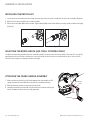
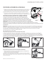
ATTACHING THE CRANK HANDLE ASSEMBLY
1. Make sure the thrust bearing is placed between both thrust washers.The
spring should be oriented with the narrow end is toward the bearing.
2. Slide the bearing, washers and spring over the shaft.
3. Carefully thread the crank handle onto the shaft and continue turning the
handle clockwise until the clutch is fully tightened.
Thrust Bearing
Spring
Race
Bearings
Crank Handle
8 | cannondownriggers.com
©2015 Johnson Outdoors Marine Electronics, Inc.
ASSEMBLY & INSTALLATION

ATTACHING THE ROD HOLDER
The locking rod holder incorporate a locking tooth design which can be easily adjusted every 15° with the soft grip knob. The
unique two piece design allows independent adjustment of the rod holder and the rod holder arm in two axes*. (Figure 6)
CAUTION: This rod holder is intended for use of up to 30 lb. test line only and is not recommended for use with
any tackle IGFA (International Game Fish Association) rated higher than 30 lb. A safety strap (not included) is
recommended for all applications.
NOTE: The rod holder assembly is not covered under warranty when used with tackle above 30 lbs. Equipment placed
in the rod holders and the loss thereof is the responsibility of the user and is in no way warranted by Johnson Outdoors,
Inc. Mounting must be in accordance with the above instructions to comply with the product warranty.
*Does not apply to Easi-Troll models.
To install the rod holder (Uni-Troll models):
1. Attach the rod holder elbow to the downrigger on the left side using the supplied spring and knob. (Figure 7)
2. Fasten rod holder to rod holder elbow using supplied spring and knob. (Figure 8)
The rod holder can be adjusted by loosening either knob until the locking teeth are free from each other. Rotate the rod
holder or arm to the desired position and re-tighten knob.
To install the rod holder (Easi-Troll models):
1. Attach the rod holder to the downrigger on the left side using the supplied spring
and knob. (Figure 9)
The rod holder can be adjusted by loosening the knob until the locking teeth are free
from each other. Rotate the rod holder to the desired position and re-tighten knob.
Figure 6
Figure 8
Figure 7
Figure 9
cannondownriggers.com | 9
©2015 Johnson Outdoors Marine Electronics, Inc.
ASSEMBLY & INSTALLATION

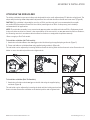
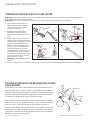
TERMINATING THE DOWNRIGGER CABLE
NOTE: Use only straight cable when routing through the terminator. Worn or kinked cable can be stressed and may
break prematurely when retrieving trolling weights.
NOTE: A set of pliers with wire cutters is recommended for this part of setup.
1. Unwind about 2 feet of cable and
thread through the rubber cushion.
Attach Swivel Snap to terminator.
2. Examine the top of the terminator
and note the order shown in the
detail to run cable.
3. Lead and pull six inches of cable
through HOLE A. Thread cable
through swivel, then up into bottom
of the terminator. Lead cable out of
HOLE B and into HOLE C. Push the
cable until its end touches the inside
of the terminator hook. Tighten cable
by squeezing terminator until it snaps
shut. Then pull at top and bottom
until drawn tight. Make sure that the
cable threads the hook.
NOTE: Use only straight cable, not kinked cable.
4. Slide the cushion over the top of the terminator and give it a test pull. The cable is now set to attach a Cannon Flash Weight™.
Close
Open
Open
Tension Adjust
Fishing Line
Gripper Pads
ATTACHING THE LINE RELEASE (UNI-RELEASE)
The Cannon Uni-Release attaches directly to the downrigger weight. Attach
fi shing line to the clip at the end of the release, and then click through a
series of increasing tension settings. The release can be used with any test
line on salt or fresh water and may be adjusted from 2 to 22 pounds of grip
tension on the line.
To change line release tension, turn tension knob to (+) to increase or (-)
to decrease. Tension also may vary according to where the line is placed in
the grips. Higher tension is on the line if it is set back toward the hinge, and
lower if set closer to the opening. To open the release, spread the release
arms with thumb and forefi nger applying pressure to the sides.
Step 2.
Rubber
Cushion
Step 1.
Step 3. Step 4.
A. CABLE
IN
C. CABLE
IN
B. CABLE
OUT
HOLE A
Swivel
HOLE B
HOLE C
Cable
Snap
&
Swivel
10 | cannondownriggers.com
©2015 Johnson Outdoors Marine Electronics, Inc.
ASSEMBLY & INSTALLATION

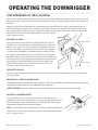
OPERATING YOUR DOWNRIGGER
After mounting the Cannon downrigger to your boat, release some line from your rod and reel so that the lure is
anywhere from 5 to 100 feet behind the boat. This is called drop back.
Attach the fi shing line fi rmly into the line release (see “Attaching the Line Release” for instructions). Lower the weight
to the desired depth as indicated on the depth meter. Place the fi shing rod in the rod holder and reel up the slack so
that your rod has a slight bend in it. When a fi sh strikes the lure, the line will separate from the release. Then you will be
free to fi ght the fi sh and bring it in on your rod and reel.
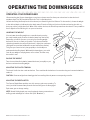
LOWERING THE WEIGHT
You can lower the trolling weight at a controlled rate by turning
the crank handle gently counter-clockwise (away from the boom).
Depending on how far you turn, you can let your trolling weight
descend as fast or as slowly as you wish. Turn the crank handle
clockwise (toward the boom) until the clutch is tight (the continuous
clicking will stop and the handle will not turn forward any further).
This gives you control to let it plunge rapidly or sink slowly to a
predetermined trolling depth. With multiple downriggers, you could
start all your weights creeping down, one at a time, and then stop
them each in turn.
RAISING THE WEIGHT
Turn the crank handle clockwise (toward the boom) as rapidly as you
desire to retrieve the trolling weight.
ADJUSTING THE CLUTCH TENSION
The clutch is built into the crank mechanism. Turn crank handle clockwise to increase the drag and counterclockwise to
reduce it.
CAUTION: Remove weight from downrigger before traveling either by water or transporting on trailer.
ADJUSTING THE DEPTH METER
The Cannon Depth Meter provides non-slip accuracy, plus easy resetting. To
reset, just slide the meter away from the reel until the gears are disengaged.
Spin meter gear to change setting.
NOTE: Actual fi shing depth may vary from depth shown on meter due to
trolling speed and weight of cannon ball. (See “Blowback”)
To Lower Weight
To Raise Weight
cannondownriggers.com | 11
©2015 Johnson Outdoors Marine Electronics, Inc.
OPERATING THE DOWNRIGGER

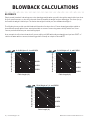
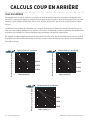
BLOWBACK
Simply stated, blowback is what happens to the downrigger weight when you pull it through the water behind your boat.
As your speed increases, so does the horizontal distance between the weight and your downrigger. The faster you go,
the farther the weight is behind you. The farther the weight is behind you, the shallower the weight is.
The following charts provide you with blowback information for three sizes of Cannon downrigger weights pulled at
three different speeds with no lures attached and with no current. Current drag, water salinity and the use of non-
Cannon products will affect your actual trolling depth.
As an example, the fi rst chart shows that if you are trolling at 4 MPH with an 8 pound weight and you have 100FT. of
cable in the water with no current; the down rigger ball is actually at a depth of about 80 FT.
Cable Length (ft.)
0
20
40
60
80
100
120
140
160
0
20
40
60
80
100
120
140
160
8-Lb Weight at 2, 4, and 6 MPH
2 MPH
4 MPH
6 MPH
Actual Depth of Weight (ft.)
Cable Length (ft.)
0
20
40
60
80
100
120
140
160
0
20
40
60
80
100
120
140
160
10-Lb Weight at 2, 4, and 6 MPH
2 MPH
4 MPH
6 MPH
Actual Depth of Weight (ft.)
Cable Length (ft.)
0
20
40
60
80
100
120
140
160
0
20
40
60
80
100
120
140
160
12-Lb Weight at 2, 4, and 6 MPH
2 MPH
4 MPH
6 MPH
Actual Depth of Weight (ft.)
12 | cannondownriggers.com
©2015 Johnson Outdoors Marine Electronics, Inc.
BLOWBACK CALCULATIONS

FREQUENTLY ASKED QUESTIONS
We have FAQs available on our website to help answer all of your Cannon questions. Visit www.cannondownriggers.com
and click on “Frequently Asked Questions” under the “Service” tab to fi nd an answer to your question.
CALL US (FOR U.S. AND CANADA)
Our customer service representatives are available Monday – Friday between 7:00am – 4:30pm CST at 800-227-6433.
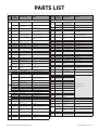
If you are calling to order parts, please have the 11-character serial number from your product, specifi c part numbers,
and credit card information available. This will help expedite your call and allow us to provide you with the best customer
service possible. You can reference the parts list located in your manual to identify the specifi c part numbers.
EMAIL US
You can email our customer service department with questions regarding your Cannon products. To email your quesiton,
visit www.cannondownriggers.com and click on “Contact Us” under the “Service” tab.
REPLACEMENT PARTS
In the U.S.A., replacement parts may be ordered directly from CANNON Parts Dept., 121 Power Drive, Mankato,
Minnesota 56001. Be sure to provide the MODEL and SERIAL numbers of your downrigger when ordering parts. Please
use the correct part numbers from the parts list. Payment for any parts ordered from the CANNON Parts Department may
be by cash, personal check, Discover Card, MasterCard or VISA. To order, call 1-800-227-6433 or FAX 1-800-527-4464.
AUTHORIZED SERVICE CENTERS
Cannon works with authorized service centers in the United States and Canada to provide parts and service for your
downrigger. Please visit our Authorized Service Center page to locate a service center in your area.
cannondownriggers.com | 13
©2015 Johnson Outdoors Marine Electronics, Inc.
SERVICE & REPAIR

EASI-TROLL ST, EASI-TROLL ST/E
UNI-TROLL 5 ST, UNI-TROLL 5 ST/E, UNI-TROLL 10 STX, UNI-TROLL 10 STX/E,
UNI-TROLL 10 STX-TS, UNI-TROLL 10 STX-TS/E
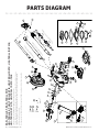
This page provides Cannon® WEEE compliance disassembly instructions.
For more information about where you should dispose of your waste equipment for recycling and recovery
and/or your European Union member state requirements, please contact your dealer or distributor from
which your product was purchased.
Tools required, but not limited to:fl at head screw driver, Phillips screw driver, socket set, pliers, wire cutters.
104
71
45
44
72
91
73
43
46
47
47
74
8
93
63
31
32
33
75
10
11
21
75
9
41
76
77
78
79
81
82
83
42
48
80
61
43
62
63
64
65
66
64
94
49
50
63
Uni-Troll Models Only
A
B
C
D
F
G
H
J
B
E
K
Uni-Troll 10 STX/Uni-Troll 10 STX TS Only
101
102
103
22
Telescoping Boom for Uni-Troll 10 STX Models
3
1
2
2a
3a
Boom and Adapter for Uni-Troll 5 ST Models
5
4
Boom and Adapter for Easi Troll Models
6
7
14 | cannondownriggers.com
©2015 Johnson Outdoors Marine Electronics, Inc.
PARTS DIAGRAM

EASI-TROLL ST, EASI-TROLL ST/E
UNI-TROLL 5 ST, UNI-TROLL 5 ST/E, UNI-TROLL 10 STX, UNI-TROLL 10 STX/E,
UNI-TROLL 10 STX-TS, UNI-TROLL 10 STX-TS/E
This page provides Cannon® WEEE compliance disassembly instructions.
For more information about where you should dispose of your waste equipment for recycling and recovery
and/or your European Union member state requirements, please contact your dealer or distributor from
which your product was purchased.
Tools required, but not limited to:fl at head screw driver, Phillips screw driver, socket set, pliers, wire cutters.
104
71
45
44
72
91
73
43
46
47
47
74
8
93
63
31
32
33
75
10
11
21
75
9
41
76
77
78
79
81
82
83
42
48
80
61
43
62
63
64
65
66
64
94
49
50
63
Uni-Troll Models Only
A
B
C
D
F
G
H
J
B
E
K
Uni-Troll 10 STX/Uni-Troll 10 STX TS Only
101
102
103
22
Telescoping Boom for Uni-Troll 10 STX Models
3
1
2
2a
3a
Boom and Adapter for Uni-Troll 5 ST Models
5
4
Boom and Adapter for Easi Troll Models
6
7
ITEM
PART
NUMBER
DESCRIPTION MODEL
BOOM ASSEMBLIES & RELATED PARTS
1
2210821
TELESCOPING BOOM
ASSEMBLY, BLACK
UNI-TROLL 10 STX
3392010
TELESCOPING BOOM
ASSEMBLY, SS
UNI-TROLL 10 STX-TS
2 2219822 CLAMP - BASE TUBE
UNI-TROLL 10 STX
UNI-TROLL 10 STX-TS
3 2219823
CLAMP - INTERMEDIATE
TUBE
UNI-TROLL 10 STX
UNI-TROLL 10 STX-TS
2A 3393300 COLLET - BASE TUBE
UNI-TROLL 10 STX
UNI-TROLL 10 STX-TS
3A 3393301 COLLET - MID TUBE
UNI-TROLL 10 STX
UNI-TROLL 10 STX-TS
4 2290828
HEAVY DUTY 24” BOOM,
BLACK
UNI-TROLL 5 ST
5 3395905 ADAPTER, BOOM END UNI-TROLL 5 ST
6 3392017 24” BOOM, BLACK EASI-TROLL ST
7 3395906 ADAPTER, BOOM EASI-TROLL ST
8 3393461
SCREW-1/4-20 X 2” SS,
PPH
ALL MODELS
9 2263103 NUT 1/4-20, NYLOCK, SS ALL MODELS
10 3990200 BOOM END ASSEMBLY ALL MODELS
11 2373450
SCREW-#8-18 X 3/8”
THRD CUT SS
ALL MODELS
CABLE SPOOLS
21
3397930 REEL, SS, 24” RETRIEVE UNI-TROLL 10 STX-TS
3397931
REEL, PLASTIC, 24”
RETRIEVE
UNI-TROLL 10 STX, UNI-TROLL 5 ST
3397904
REEL, PLASTIC, 18”
RETRIEVE
EASI-TROLL ST
22 3393412
SCREW SET 5/16-18X1
HDP RIE
ALL MODELS
COUNTERS & GEARS
31
0220477 3 DIGIT COUNTER ALL SAE (COUNT IN FEET)
3320011 METRIC 3 DIGIT COUNTER ALL METRIC (COUNT IN METERS)
32
3392223
COUNTER GEAR, 28
TOOTH
SAE UNI-TROLL MODELS (ALL)
3392229
COUNTER GEAR, 12
TOOTH
METRIC UNI-TROLL MODELS (ALL)
3333003 COUNTER GEAR, UT HP SAE EASI-TROLL ST
3392227
COUNTER GEAR, 15
TOOTH
METRIC EASI-TROLL ST
33
3392222 REEL GEAR, 56 TOOTH SAE UNI-TROLL MODELS (ALL)
3392228 REEL GEAR, 72 TOOTH METRIC UNI-TROLL MODELS (ALL)
3333004 REEL GEAR, UT HP SAE EASI-TROLL ST
3392226 REEL GEAR, 69 TOOTH METRIC EASI-TROLL ST
DOWNRIGGER FRAME & DECALS
41
3392540 FRAME, BLACK ALL BLACK MODELS
3392541 FRAME, WHITE UNI-TROLL 10 STX-TS
42
3396420 CLUTCH COVER, BLACK ALL BLACK MODELS
3396421 CLUTCH COVER, WHITE UNI-TROLL 10 STX-TS
43 3395634 DECAL, SIDE, BLACK ALL MODELS
44 3393130
NUT-HEX 1/4-20 SS, RIE
COATED
ALL MODELS
45 3394722 INSERT, PUSH ON ALL MODELS
46 9040040
HDW BOLT, 1/4-20,
ROLLED THD HOOK
ALL UNI-TROLL MODELS
47 3393130
NUT-HEX, 1/4-20 SS
300RS
ALL UNI-TROLL MODELS
48 3393480
SCREW-#10X1” PPH
HI-LO SS
ALL MODELS
49 3394702 INSERT, BASE, LO-PRO ALL MODELS
50 2373450
SCREW-#8-18 X 3/8”
THRD CUT SS
ALL MODELS
ITEM
PART
NUMBER
DESCRIPTION MODEL
ROD HOLDER
61
3991904
DUAL ACCESS ROD
HOLDER ASSEMBLY
ALL UNI-TROLL MODELS
3991906
SINGLE ACCESS ROD
HOLDER ASSEMBLY
EASI-TROLL ST
62 3392033 ROD TUBE ALL MODELS
63 3390101 SOFT GRIP KNOB (2 EA) ALL MODELS
64 2287002
HDW SPRING, RELEASE
PIN
ALL MODELS
65 3393130
NUT 1/4-20, SS, RIE
COATED
ALL UNI-TROLL MODELS
66 3394200
ARM, DUAL AXIS ROD
HOLDER
ALL UNI-TROLL MODELS
DRIVE COMPOUNDS
71 3994210 HANDLE ASSEMBLY ALL MODELS
72 9400040 HDW SPRING, CRANK ALL MODELS
73 3391737 WASHER, THRUST, 17-7 SS ALL MODELS
74 9010280 HDW BEARING, THRUST ALL MODELS
75 9010001 BEARING, NYLINER ALL MODELS
76 1080001 SHAFT, REEL ET/UT ALL MODELS
77 3391990
PLATE-CLUTCH/BRAKE
REEL
ALL MODELS
78 3391710 PAD-CLUTCH ALL MODELS
79 3391995 PLATE-RATCHET BRAKE ALL MODELS
80 1000904 ASY SHAFT RATCHET UT6 ALL MODELS
81 9100160 DOG RATCHET ALL MODELS
82 9400070 HDW SPRING DOG ALL MODELS
83 9250003
HDW PIN 3/16” X 7/8”
DOWEL
ALL MODELS
MOUNTING BASE
n
3771930
MOUNTING BASE
ASSEMBLY (91,92,93)
ALL MODELS
91 3391955 BASE MOUNT, MAG ST ALL MODELS
93 3393000
RETAINING RING 1/4”
SHAFT
ALL MODELS
94 3991913 SWIVEL BASE ASSEMBLY
UNI-TROLL 10 STX
UNI-TROLL 10 STX-TS
A 3396430 TOP, SWIVEL, MOLDED
B 9010004
HDW BEARING, SWIVEL
BASE
C 3391958 PLATE, SUPPORT TOP
D 3391923 BASE, SWIVEL MOLDED
E 3391999
PLATE-INDEX, SWIVEL
BASE
F 3392600 PIN-RELEASE
G 2287002
HDW SPRING, RELEASE
PIN
H 2277001
HDW, RETAINER RELEASE
NUT
J 2249001 HDW KNB RELEASE PIN
K 2372100
SCREW-#8-18 X 5/8
THD* SS
INCLUDED LINE END ACCESSORIES
101 9100100 CON TERMINATOR ALL MODELS
102 9100101
CUSHION SLEEVE,
TERMINATOR
ALL MODELS
103 9100620
HDW SNAP SWIVEL 4/0-
37 MARLIN
ALL MODELS
104
2277002 LINE RELEASE ALL BLACK MODELS
2200109
SALTWATER LINE
RELEASE
UNI-TROLL 10 STX-TS
MOUNTING HARDWARE
n
2994894
BAG ASSEMBLY,
MOUNTING HARDWARE
ALL MODELS
cannondownriggers.com | 15
©2015 Johnson Outdoors Marine Electronics, Inc.
PARTS LIST

ENVIRONMENTAL COMPLIANCE STATEMENT:
It is the intention of JOME to be a responsible corporate citizen, operating in compliance with known and applicable
environmental regulations, and a good neighbor in the communities where we make or sell our products.
WEEE DIRECTIVE:
EU Directive 2002/96/EC “Waste of Electrical and Electronic Equipment Directive (WEEE)” impacts most distributors,
sellers, and manufacturers of consumer electronics in the European Union. The WEEE Directive requires the producer of
consumer electronics to take responsibility for the management of waste from their products to achieve environmentally
responsible disposal during the product life cycle.
WEEE compliance may not be required in your location for electrical & electronic equipment (EEE), nor may it be
required for EEE designed and intended as fi xed or temporary installation in transportation vehicles
such as automobiles, aircraft, and boats. In some European Union member states, these vehicles are
considered outside of the scope of the Directive, and EEE for those applications can be considered
excluded from the WEEE Directive requirement.
This symbol (WEEE wheelie bin) on product indicates the product must not be disposed of with other
household refuse. It must be disposed of and collected for recycling and recovery of waste EEE.
Johnson Outdoors Inc. will mark all EEE products in accordance with the WEEE Directive. It is our goal
to comply in the collection, treatment, recovery, and environmentally sound disposal of those products; however, these
requirement do vary within European Union member states. For more information about where you should dispose
of your waste equipment for recycling and recovery and/or your European Union member state requirements, please
contact your dealer or distributor from which your product was purchased.
DISPOSAL:
Johnson Outdoors Inc. products are not subject to the disposal regulations EAG-VO (electric devices directive) that
implements the WEEE directive. Nevertheless never dispose of your product in a garbage bin but at the proper place of
collection of your local town council.
Never dispose of battery in a garbage bin. Comply with the disposal directions of the manufacturer or his representative
and dispose of them at the proper place of collection of your local town council.
WARNING: This product contains chemicals known to the State of California to cause cancer and birth defects or
other reproductive harm.
16 | cannondownriggers.com
©2015 Johnson Outdoors Marine Electronics, Inc.
COMPLIANCE STATEMENTS

ENVIRONMENTAL COMPLIANCE STATEMENT:
It is the intention of JOME to be a responsible corporate citizen, operating in compliance with known and applicable
environmental regulations, and a good neighbor in the communities where we make or sell our products.
WEEE DIRECTIVE:
EU Directive 2002/96/EC “Waste of Electrical and Electronic Equipment Directive (WEEE)” impacts most distributors,
sellers, and manufacturers of consumer electronics in the European Union. The WEEE Directive requires the producer of
consumer electronics to take responsibility for the management of waste from their products to achieve environmentally
responsible disposal during the product life cycle.
WEEE compliance may not be required in your location for electrical & electronic equipment (EEE), nor may it be
required for EEE designed and intended as fi xed or temporary installation in transportation vehicles
such as automobiles, aircraft, and boats. In some European Union member states, these vehicles are
considered outside of the scope of the Directive, and EEE for those applications can be considered
excluded from the WEEE Directive requirement.
This symbol (WEEE wheelie bin) on product indicates the product must not be disposed of with other
household refuse. It must be disposed of and collected for recycling and recovery of waste EEE.
Johnson Outdoors Inc. will mark all EEE products in accordance with the WEEE Directive. It is our goal
to comply in the collection, treatment, recovery, and environmentally sound disposal of those products; however, these
requirement do vary within European Union member states. For more information about where you should dispose
of your waste equipment for recycling and recovery and/or your European Union member state requirements, please
contact your dealer or distributor from which your product was purchased.
DISPOSAL:
Johnson Outdoors Inc. products are not subject to the disposal regulations EAG-VO (electric devices directive) that
implements the WEEE directive. Nevertheless never dispose of your product in a garbage bin but at the proper place of
collection of your local town council.
Never dispose of battery in a garbage bin. Comply with the disposal directions of the manufacturer or his representative
and dispose of them at the proper place of collection of your local town council.
WARNING: This product contains chemicals known to the State of California to cause cancer and birth defects or
other reproductive harm.
cannondownriggers.com | 17
©2015 Johnson Outdoors Marine Electronics, Inc.
NOTES

A Johnson Outdoors Company
Cannon Consumer & Technical Service
Johnson Outdoors Marine Electronics, Inc.
PO Box 8129
Mankato, MN 56002-8129
121 Power Drive
Mankato, MN 56001
Phone (800) 227-6433
Fax (800) 527-4464
cannondownriggers.com
©2015 Johnson Outdoors Marine Electronics, Inc.
All rights reserved.
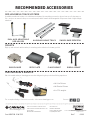
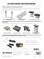
For a complete listing of Cannon accessories, visit cannondownriggers.com
• Uni-Line Release
• Uni-Stacker Release
• 4 to 12 lb. weights
RECOMMENDED ACCESSORIES
ROD HOLDERS & TRACK SYSTEMS
Incredible versatile rod holders, rock-solid bases and plates. It’s everything you need to rig your boat up to fit the way you
fish - and you can mount it all up on our track system, which features interchangeable components made of high-strength
aluminum.
MOUNTS
Rig it up and reel ‘em in with a variety of mounting options suited to fit the way you fish.
LINE RELEASES & WEIGHTS
We offer a wide variety of downrigger accessories designed to give you the best fishing experience:
ALUMINUM MOUNT TRACK
DUAL AXIS ADJUSTABLE
ROD HOLDER
SWIVEL BASE PEDESTAL
Follow us:
CLAMP MOUNTSWIVEL BASE GIMBAL MOUNT
DECK PLATE
Part #3397136 ECN 37211 Rev F 02/16

For a complete listing of Cannon accessories, visit cannondownriggers.com
• Uni-Line Release
• Uni-Stacker Release
• 4 to 12 lb. weights
RECOMMENDED ACCESSORIES
ROD HOLDERS & TRACK SYSTEMS
Incredible versatile rod holders, rock-solid bases and plates. It’s everything you need to rig your boat up to fit the way you
fish - and you can mount it all up on our track system, which features interchangeable components made of high-strength
aluminum.
MOUNTS
Rig it up and reel ‘em in with a variety of mounting options suited to fit the way you fish.
LINE RELEASES & WEIGHTS
We offer a wide variety of downrigger accessories designed to give you the best fishing experience:
ALUMINUM MOUNT TRACK
DUAL AXIS ADJUSTABLE
ROD HOLDER
SWIVEL BASE PEDESTAL
Follow us:
CLAMP MOUNTSWIVEL BASE GIMBAL MOUNT
DECK PLATE
EASI-TROLL ST
UNI-TROLL ST
TREUIL DE PÊCHE MANUEL
MANUEL DE L’UTILISATEUR
UNI-TROLL™ 10 STX-TS
UNI-TROLL™ 10 STX
UNI-TROLL™ 5 ST
EASI-TROLL™ ST

Modèle : _____________________________________________________________________
Numéro de série : ______________________________________________________________
Date de l’achat : _______________________________________________________________
Magasin où l’achat a été effectué : ___________________________________________________
Veuillez lire attentivement ce manuel de l’utilisateur. Suivez toutes les instructions et tenez compte de toutes les consignes de sécurité et les
mises en garde décrites ci-dessous. L’utilisation de ce treuil de pêche n’est autorisée que pour les personnes qui ont lu et compris ces consignes pour
l’utilisateur. Les mineurs peuvent utiliser ce moteur uniquement sous la supervision d’un adulte.
ATTENTION: Votre treuil de pêche Cannon ne devrait être utilisé que pour son intention prévue. L’utilisation inappropriée annulera la garantie et
pourrait créer un risque de sécurité.
MISE EN GARDE: Les personnes dont la capacité à faire fonctionner le treuil de pêche est affaiblie par l’alcool, la drogue, les médicaments ou d’autres
substances ne sont pas autorisées à utiliser ce produit.
MERCI
Merci d’avoir acheté un treuil de pêche Cannon. Nous avons conçu votre nouveau treuil de pêche pour qu’il soit un
outil précis et fi able qui vous permettra d’améliorer le contrôle de la pêche et d’accroître votre capacité d’attraper des
poissons. Nous espérons que vous aimerez utiliser notre nouveau treuil de pêche et que vous profi terez des avantages
de la pêche en profondeur contrôlée pendant des années en respectant toujours les pratiques sécuritaires et les lois en
matière de navigation toutes les fois que vous pêcherez.
Ce manuel traite de l’installation et du fonctionnement de votre treuil de pêche. Lisez attentivement ce manuel avant
d’utiliser votre nouveau treuil de pêche Cannon. Conservez ce manuel pour référence future.
N’OUBLIEZ PAS DE CONSERVER VOTRE REÇU ET D’ENREGISTRER IMMÉDIATEMENT VOTRE TREUIL DE PÊCHE.
Pour recevoir tous les avantages de la garantie de votre produit, veuillez remplir le formulaire d’enregistrement ci-joint et
le retourner par la poste. Vous pouvez aussi remplir votre enregistrement sur notre site Web à cannondownriggers.com.
LOCALISATION DE VOTRE NUMÉRO DE SÉRIE
Le numéro de série à 11 caractères Cannon est très important. Cela permet de déterminer le modèle spécifi que et l’année de fabrication. Lorsque vous
contactez le service à la clientèle ou que vous enregistrez votre article, vous aurez besoin du numéro de série de votre article. Nous vous suggérons
d’inscrire le numéro de série dans l’espace fourni ci dessous afi n qu’il soit disponible ultérieurement.
MANUEL CE D’UN MASTER (CE CERTIFIED MODELS)
Le numéro de série de votre treuil de pêche
Easi-Troll ou Uni-Troll Cannon est situé vers
l’intérieur du fond du cadr.
Made by Cannon
Johnson Outdoors
Marine Electronics, Inc.
121 Power Drive
Mankato, MN 56001 USA
Downriggers
Produced in 2015
EASI-TROLL ST MANUAL DOWNRIGGER
MODEL 1901020
SER NO K365 CN12345
20 | cannondownriggers.com
©2015 Johnson Outdoors Marine Electronics, Inc.
EXEMPLE
La page est en cours de chargement...
La page est en cours de chargement...
La page est en cours de chargement...
La page est en cours de chargement...
La page est en cours de chargement...
La page est en cours de chargement...
La page est en cours de chargement...
La page est en cours de chargement...
La page est en cours de chargement...
La page est en cours de chargement...
La page est en cours de chargement...
La page est en cours de chargement...
La page est en cours de chargement...
La page est en cours de chargement...
-
 1
1
-
 2
2
-
 3
3
-
 4
4
-
 5
5
-
 6
6
-
 7
7
-
 8
8
-
 9
9
-
 10
10
-
 11
11
-
 12
12
-
 13
13
-
 14
14
-
 15
15
-
 16
16
-
 17
17
-
 18
18
-
 19
19
-
 20
20
-
 21
21
-
 22
22
-
 23
23
-
 24
24
-
 25
25
-
 26
26
-
 27
27
-
 28
28
-
 29
29
-
 30
30
-
 31
31
-
 32
32
-
 33
33
-
 34
34


Cannon UNI-TROLL 5 ST Manuel utilisateur
- Taper
- Manuel utilisateur
- Ce manuel convient également à
dans d''autres langues
- English: Cannon UNI-TROLL 5 ST User manual
Documents connexes
-
Cannon LAKE-TROLL Manuel utilisateur
-
Cannon 10 STX TS Le manuel du propriétaire
-
Cannon 1901200 Manuel utilisateur
-
Cannon 2450163 Manuel utilisateur
-
-
Cannon Pedestal Le manuel du propriétaire
-
-
Cannon Optimum Quick Reference Manual
Autres documents
-
Protocol 8512-3 Telescopic Fishing Set Manuel utilisateur
-
 OCANNON 1903002 Low-Profile Swivel Base Manuel utilisateur
-
Humminbird 410190-1 Guide d'installation
-
Humminbird SOLIX Series Guide d'installation
-
MINN KOTA Riptide Manuel utilisateur
-
MINN KOTA POWERDRIVE V2 Manuel utilisateur
-
-
-
3M Petrifilm™ Staph Express Disks 6492, 20 each/box Mode d'emploi
