KTM 79412945044 Le manuel du propriétaire
- Taper
- Le manuel du propriétaire

INFORMATION
KTM PowerParts, HUSQVARNA Motorcycles Accessories
KTM Sportmotorcycle GmbH
Stallhofnerstraße 3
A-5230 Mattighofen
www.ktm.com
Husqvarna Motorcycles GmbH
Stallhofnerstraße 3
A-5230 Mattighofen
www.husqvarna-motorcycles.com
KICK-STARTER KIT 3.213.672
*3213672*
79412945044 02.2018

Le agradecemos que se haya decidido por este producto.
Este producto de alta calidad está probado para la competición y se ha desarrollado específi camente para las exigencias de este deporte. Para poder garantizar
los máximos niveles de seguridad y funcionalidad, es imprescindible que el producto se monte correctamente. Por este motivo, es muy importante que siga las
instrucciones del manual de montaje o que se ponga en contacto con su concesionario autorizado.
El (cuasi) fabricante y el proveedor de este producto no se harán responsables del montaje y el uso incorrectos.
¡Muchas gracias!
Wir freuen uns, dass Sie sich für dieses Produkt entschieden haben.
Unser hochwertiges Qualitätsprodukt ist rennerprobt und wurde speziell für sportliche Herausforderungen entwickelt. Eine korrekte Montage des Produktes
ist unerlässlich, um ein Maximum an Sicherheit und Funktionalität gewährleisten zu können. Bitte befolgen Sie daher die Montageanleitung oder wenden Sie
sich an Ihren autorisierten Fachhändler.
Für falsche Montage oder Verwendung dieses Produktes kann der (Quasi-)Hersteller bzw. Lieferant nicht zur Verantwortung gezogen werden.
Vielen Dank.
Thank you for choosing this product.
Our high quality product has been tested under racing conditions and was developed specifi cally for use in sports activities. Correct installation of the product
is essential to ensure that a maximum degree of safety and functionality is achieved. Therefore, please follow the installation instructions or contact your
authorized dealer.
The (quasi) manufacturer or supplier cannot be held responsible for products that are incorrectly mounted or inappropriately used.
Thank you.
Grazie per aver scelto questo prodotto.
Questo nostro prodotto di pregiata qualità è collaudato nelle competizioni ed è stato sviluppato specifi camente per gare sportive. Il montaggio corretto del prodotto
è fondamentale per garantirne la massima sicurezza e funzionalità. Rispetti quindi le istruzioni di montaggio o rivolgersi al proprio concessionario autorizzato.
Il produttore (detentore del marchio)/fornitore non può essere considerato responsabile per un montaggio o impiego errato del presente prodotto.
Vi ringraziamo per l’attenzione!
Merci d‘avoir porté votre choix sur ce produit.
Notre produit de haute qualité est éprouvé pour les compétitions et a été conçu spécialement pour un usage sportif. Un montage approprié du produit est
indispensable pour garantir une sécurité et une fonctionnalité maximales du véhicule. C‘est pourquoi nous vous invitons à suivre scrupuleusement le manuel
de montage ou à vous adresser à votre revendeur agréé.
En cas de montage ou d‘utilisation non conformes de ce produit, le (quasi) constructeur ou le fournisseur déclinent toute responsabilité.
Merci !
9 ENGLISH
15 ITALIANO
21 FRANÇAIS
27 ESPAÑOL
3 DEUTSCH

3
ESPANOL FRANCAIS ITALIANO ENGLISH DEUTSCH
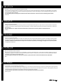
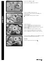
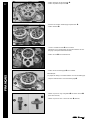
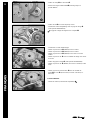
Vorarbeit
- Motor ausbauen (s. Reparaturanleitung).
HINWEIS
Zur besseren Darstellung werden die folgenden Arbeits-
schritte bei ausgebautem Motor gezeigt. Ein Ausbau ist nicht
erforderlich.
Montage
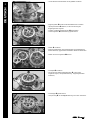
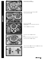
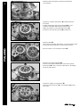
- Schrauben entfernen.
- Schrauben entfernen.
- Schrauben entfernen.
- Schraube mit Scheibe entfernen.
- Kupplungsdeckel abnehmen.
- Passhülsen entfernen.
- Kupplungsdeckeldichtung abnehmen.
- Motor auf Zünd-OT stellen.
- Blockierschraube (Spezialwerkzeug 113080802) einschrauben.
- Schrauben über Kreuz lösen und entfernen.
- Federteller abnehmen.
- Tellerfeder abnehmen.
Alle Arbeiten, die mit diesem Symbol gekennzeichnet sind, erfordern Fachkenntnisse und technisches Verständnis.
Lassen Sie diese Arbeiten, im Interesse Ihrer eigenen Sicherheit, in einer autorisierten Fachwerkstatt durchführen!
Dort wird Ihr Motorrad von speziell geschulten Fachkräften mit dem erforderlichen Spezialwerkzeug optimal betreut.
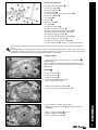
Lieferumfang
2x Bundschraube M6x20
1x Nadelkranz
1x Sicherungsring
1x Wellendichtring
1x Kickstartersperrrad
1x Fassonscheibe
1x Scheibe
1x Feder
1x Anschlagstück
1x Scheibe
1x Sicherungsblech
1x Kickstarterwelle
1x Kickstarterhebel kpl.
1x Kupplungsdeckeldichtung innen
1x Kickstarterrad
1x Kickstarterzwischenrad
1x Kickstarterfeder
1x Senkkopfschraube M8x20
1x Sicherungsring (optional, wenn nicht vormontiert)

ESPANOL FRANCAIS ITALIANO ENGLISH DEUTSCH
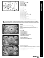
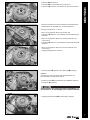
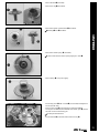
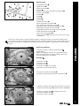
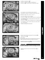
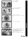
4- Vorspannring abnehmen.
- Druckkappe abnehmen.
- Die obersten Kupplungsbelaglamellen entnehmen.
- Druckpilz entfernen.
- Sicherungsblech aufbiegen.
- Kupplungsmitnehmer mit Kupplungshalter (Spezialwerkzeug
590.29.003.100) gegenhalten.
- Mutter mit Sicherungsblech entfernen.
- Kupplungsmitnehmer mit Scheibe abnehmen.
HINWEIS
Die Scheibe klebt meist am Kupplungsmitnehmer.
- Kupplungskorb komplett abnehmen.
- Nadelkranz auf Kickstarterwelle (beides Lieferumfang)
montieren.
- Kickstarterrad (Lieferumfang) montieren.

5
ESPANOL FRANCAIS ITALIANO ENGLISH DEUTSCH
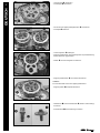
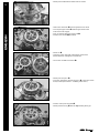
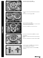
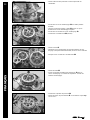
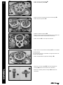
- Scheibe (Lieferumfang) montieren.
- Sicherungsring (Lieferumfang) montieren.
- Kickstartersperrrad (Lieferumfang) montieren.
Markierung und fl uchten.
- Kickstarterfeder (Lieferumfang) montieren.
Das Ende der Kickstarterfeder greift in die Bohrung ein.
- Feder (Lieferumfang) montieren.
- Anschlagstück mit Schrauben (alles Lieferumfang)
montieren und mit 10 Nm festziehen (Loctite 243).
- Sicherungsring vom Lagerzapfen entfernen (wenn vormon-
tiert).
- Kickstarterzwischenrad (Lieferumfang) ölen (Motoröl 15W/50)
und auf dem Lagerzapfen montieren.
Bund zeigt nach unten.
- Scheibe (Lieferumfang) und Sicherungsring montieren.

ESPANOL FRANCAIS ITALIANO ENGLISH DEUTSCH
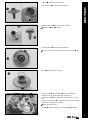
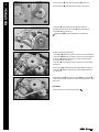
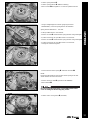
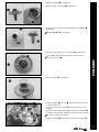
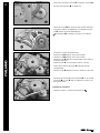
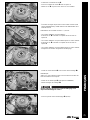
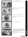
6- Vormontierte Kickstarterwelle wie abgebildet montieren.
- Kupplungskorb auf die Getriebeantriebswelle schieben.
- Ölpumpenzahnrad drehen, bis die Verzahnung des
Kupplungskorbs eingreift.
- Scheibe mit Kupplungsmitnehmer aufschieben.
- Sicherungsblech (Lieferumfang) positionieren.
- Mutter montieren.
- Kupplungsmitnehmer mit Kupplungshalter (Spezialwerkzeug
590.29.003.100) gegenhalten und Mutter mit 80 Nm festziehen.
- Mutter mit Sicherungsblech sichern.
- Druckpilz montieren.
- Die obersten Kupplungsbelaglamellen in den Kupp-
lungskorb legen (s. Reparaturanleitung - Kupplungslamellen
einbauen).
- Druckkappe positionieren.
- Vorspannring mit der Top Markierung nach oben montieren.

7
ESPANOL FRANCAIS ITALIANO ENGLISH DEUTSCH
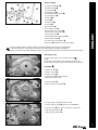
- Tellerfeder positionieren.
- Federteller mit der I Markierung positionieren.
- Schrauben montieren und über Kreuz mit 6 Nm festziehen.
- Mit einem Haarlineal und einer Fühlerlehre (Spezialwerkzeug
59029041100) die Tellerfeder auf Verzug kontrollieren.
Verzug der Tellerfeder 0... 0,10 mm
» Wenn der angegebene Wert nicht erreicht wird:
- Schrauben entfernen und Federteller mit der Markierung II
montieren.
» Wenn der angegebene Wert nach erneuter Kontrolle nicht
erreicht wird:
- Schrauben entfernen und Federteller mit der Markierung III
montieren.
» Wenn der angegebene Wert nach erneuter Kontrolle nicht
erreicht wird:
- Kupplungsbelaglamellen wechseln.
- Kickstarterfeder spannen und in Bohrung einhängen.
HINWEIS
Darauf achten, dass der Abstand der Kickstarterfeder zur
Kickstarterwelle rundum gleich groß ist.
- Blockierschraube (Spezialwerkzeug 113080802) entfernen.
- Passhülsen montieren.
Den Kickstarter ohne Kupplungsdeckel nicht betätigen, an-
sonsten kann es zur Beschädigung des Gehäuses kommen!
- Kupplungsdeckeldichtung (Lieferumfang) aufl egen.

ESPANOL FRANCAIS ITALIANO ENGLISH DEUTSCH
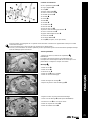
8- Sicherungsring und Verschlußstopfen entfernen.
- Wellendichtring (Lieferumfang) bündig einschlagen.
- Schraube vom Wasserpumpendeckel entfernen.
- Ausgleichswelle mit Absteckdorn (Spezialwerkzeug
78129032000) positionieren.
Markierung und Absteckdorn sind ausgerichtet.
- Kupplungsdeckel positionieren.
- Schrauben (M6x25) montieren, aber noch nicht festziehen.
- Schrauben (M6x55) montieren, aber noch nicht festziehen.
- Schraube (M6x30) montieren und alle Schrauben über
Kreuz mit 10 Nm festziehen.
- Schraube mit Unterlegscheibe montieren und mit 10 Nm
festziehen.
- Absteckdorn (Spezialwerkzeug 78129032000) entfernen.
- Schraube (M6x25) montieren und mit 10 Nm festziehen
(Loctite 243).
- Kickstarterhebel mit Fassonscheibe und Schraube
(alles Lieferumfang) montieren und mit 25 Nm festziehen (Loc-
tite 2701).
Nacharbeit
- Motor einbauen (s. Reparaturanleitung).

9
ESPANOL FRANCAIS ITALIANO ENGLISH DEUTSCH
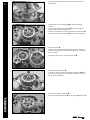
Preparatory work
- Remove the engine (see the repair manual).
NOTE
For purposes of illustration, the following operations are
shown with the engine removed. Removal is not necessary.
Assembly
- Remove screws .
- Remove screws .
- Remove screws .
- Remove screw with the washer.
- Take off the clutch cover.
- Remove dowels .
- Take off clutch cover gasket .
- Set the engine to ignition top dead center.
- Screw in locking screw (special tool 113080802).
- Loosen screws in a crisscross pattern and remove.
- Take off spring retainer .
- Take off spring washer .
All work marked with this symbol requires specialist knowledge and technical understanding.
In the interest of your own safety, have these jobs performed by an authorized workshop.
There, your motorcycle will be optimally cared for by specially trained experts using the specialist tools required.
Scope of supply
2x collar screw M6x20
1x needle bearing
1x locking ring
1x shaft seal ring
1x kick starter ratchet wheel
1x special washer
1x washer
1x spring
1x stop piece
1x washer
1x lock washer
1x kick-starter shaft
1x kick starter lever compl.
1x inner clutch cover gasket
1x kick starter gear
1X intermediate kick starter gear
1x kick starter spring
1x countersunk screw M8x20
1x lock ring (optional, if not preassembled)

ESPANOL FRANCAIS ITALIANO ENGLISH DEUTSCH
10 - Take off pretension ring .
- Take off clutch pressure plate .
- Remove the uppermost clutch facing discs .
- Remove pressure piece .
- Bend up lock washer .
- Hold inner clutch hub with clutch holder (special tool
590.29.003.100).
- Remove nut with the lock washer.
- Take off inner clutch hub with washer.
NOTE
The washer usually sticks to the inner clutch hub.
- Take off outer clutch hub completely.
- Mount needle bearing on kick-starter shaft (both included).
- Mount kick starter gear (included).

11
ESPANOL FRANCAIS ITALIANO ENGLISH DEUTSCH
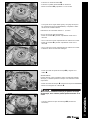
- Mount washer (included).
- Mount lock ring (included).
- Mount kick-starter ratchet wheel (included).
Marking and are fl ush.
- Mount kick starter spring (included).
The end of the kick starter spring engages in hole .
- Mount spring (scope of supply).
- Mount stop piece with screws (all included) and tighten to
10 Nm (Loctite 243).
- Remove lock ring from bearing pin (if preassembled).
- Oil (engine oil 15W/50) intermediate kick starter gear (includ-
ed) and mount on the bearing pin.
Collar points downward.
- Mount washer (included) and mount lock ring .

ESPANOL FRANCAIS ITALIANO ENGLISH DEUTSCH
12 - Mount preassembled kick-starter shaft as shown.
- Slide outer clutch hub onto the gearbox main shaft.
- Turn oil pump gear wheel until the gear teeth of the
outer clutch hub engage.
- Push on washer with inner clutch hub .
- Position lock washer (included).
- Mount nut .
- Hold inner clutch hub with clutch holder (special tool
590.29.003.100) and tighten nut to 80 Nm.
- Secure the nut with lock washer .
- Mount pressure piece .
- Place the uppermost clutch facing discs in the outer clutch
hub (see the repair manual – Installing clutch discs).
- Position clutch pressure plate .
- Mount pretension ring with the Top marking facing up.

13
ESPANOL FRANCAIS ITALIANO ENGLISH DEUTSCH
- Position spring washer .
- Position spring retainer with the I marking.
- Mount screws and tighten in a crisscross pattern to 6 Nm.
- Using a straightedge and a feeler gauge (special tool
59029041100), check the spring washer for distortion.
Spring washer distortion 0... 0.10 mm
» If the specifi ed value is not reached:
- Remove screws and mount the spring retainer using marking II.
» If, after rechecking, the specifi ed value is not reached:
- Remove screws and mount the spring retainer using marking III.
» If, after rechecking, the specifi ed value is not reached:
- Change the clutch facing discs.
- Tension the kick starter spring and hook into hole .
NOTE
Ensure that the distance from the kick starter spring to the kick
starter shaft is the same all around.
- Remove locking screw (special tool 113080802).
- Mount dowels .
Do not activate the kick-starter system without the clutch
cover as damage to the housing may result!
- Position clutch cover gasket (included).

ESPANOL FRANCAIS ITALIANO ENGLISH DEUTSCH
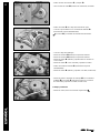
14 - Remove lock ring and plug .
- Drive in shaft seal ring (included) until fl ush.
- Remove screw from water pump cover.
- Position balancer shaft with marking mandrel (special
tool 78129032000).
Marking and marking mandrel are aligned.
- Position clutch cover.
- Mount screws (M6X25) but do not tighten them yet.
- Mount screws (M6X55) but do not tighten them yet.
- Mount screw (M6X30) and tighten all screws in a crisscross
pattern to 10 Nm.
- Mount screw with the washer and tighten to 10 Nm.
- Remove marking mandrel (special tool 78129032000).
- Mount screw (M6x25) and tighten to 10 Nm (Loctite 243).
- Mount kick-starter lever with special washer and screw
(all included) and tighten to 25 Nm (Loctite 2701).
Final steps
- Install the engine (see the repair manual).

15
ESPANOL FRANCAIS ITALIANO ENGLISH DEUTSCH
Operazione preliminare
- Smontare il motore (v. manuale di riparazione).
AVVERTENZA
Ai fi ni di una maggiore chiarezza, le seguenti fasi di lavoro
verranno rappresentate con motore smontato. Non è però
necessario effettuarne lo smontaggio.
Montaggio
- Rimuovere le viti .
- Rimuovere le viti .
- Rimuovere le viti .
- Rimuovere la vite con la rondella.
- Rimuovere il coperchio della frizione.
- Rimuovere le bussole di centraggio .
- Rimuovere la guarnizione del coperchio della frizione .
- Posizionare il motore sul punto morto superiore di accensione.
- Avvitare la vite di bloccaggio (utensile speciale 113080802).
- Allentare e rimuovere le viti in sequenza incrociata.
- Rimuovere il piattello molla .
- Rimuovere la molla a tazza .
Tutti i lavori contrassegnati con questo simbolo richiedono competenze tecniche e comprensione della materia.
Per la vostra sicurezza, far eseguire questi interventi presso un’offi cina autorizzata che si occuperà della vostra mo-
tocicletta in modo ottimale, impiegando manodopera specializzata e addestrata, e utilizzando i necessari utensili
speciali.
Materiale fornito
2 viti fl angiate M6x20
1 gabbia a rullini
1 anello di sicurezza
1 paraolio
1 ruota a denti di arresto del pedale di avviamento
1 rondella sagomata
1 rondella
1 molla
1 battuta
1 rondella
1 rosetta di sicurezza
1 albero del pedale di avviamento
1 leva del pedale di avviamento compl.
1 guarnizione interna del coperchio della frizione
1 ingranaggio del pedale di avviamento
1 ingranaggio intermedio del pedale di avviamento
1 molla del pedale di avviamento
1 vite a testa svasata M8x20
1 anello di sicurezza (opzionale, nel caso in cui non sia già
premontato)

ESPANOL FRANCAIS ITALIANO ENGLISH DEUTSCH
16 - Rimuovere l’anello di precarica .
- Rimuovere il tappo di compressione .
- Rimuovere i primi dischi guarniti della frizione posti più in
alto .
- Rimuovere il cuscinetto reggispinta .
- Aprire la rosetta di sicurezza .
- Tenere fermo il mozzetto della frizione con il fermo frizione
(utensile speciale 590.29.003.100).
- Rimuovere il dado con la rosetta di sicurezza.
- Rimuovere il mozzetto della frizione con la rondella.
AVVERTENZA
Solitamente la rondella rimane attaccata al mozzetto della
frizione.
- Rimuovere completamente la campana della frizione .
- Montare la gabbia a rullini sull’albero del pedale di
avviamento (entrambi in dotazione).
- Montare l’ingranaggio del pedale di avviamento (in
dotazione).

17
ESPANOL FRANCAIS ITALIANO ENGLISH DEUTSCH
- Montare la rondella (in dotazione).
- Montare l’anello di sicurezza (in dotazione).
- Montare la ruota a denti di arresto del pedale di avviamento
(in dotazione).
I riferimenti e sono allineati.
- Montare la molla del pedale di avviamento (in dotazione).
L’estremità della molla del pedale di avviamento deve
innestarsi nel foro .
- Montare la molla (in dotazione).
- Montare la battuta con le viti (tutto in dotazione) e serrare
a 10 Nm (Loctite 243).
- Rimuovere l’anello di sicurezza dal perno di banco (se pre-
montato).
- Lubrifi care l’ingranaggio intermedio del pedale di avviamento
(in dotazione) (olio motore 15W/50) e montarlo sul perno di banco.
Il collare è rivolto verso il basso.
- Montare la rondella (in dotazione) e l’anello di sicurezza .

ESPANOL FRANCAIS ITALIANO ENGLISH DEUTSCH
18 - Montare l’albero del pedale di avviamento premontato
come illustrato.
- Spingere la campana della frizione sull’albero primario
del cambio.
- Ruotare l’ingranaggio della pompa dell’olio fi no a far
innestare la dentatura della campana della frizione.
- Infi lare la rondella con il mozzetto della frizione .
- Posizionare la rosetta di sicurezza (in dotazione).
- Montare il dado .
- Tenere fermo il mozzetto della frizione con il fermo frizione (uten-
sile speciale 590.29.003.100) e serrare il dado a 80 Nm.
- Bloccare il dado con la rosetta di sicurezza .
- Montare il cuscinetto reggispinta .
- Inserire nella campana della frizione i primi dischi guarniti
della frizione in alto (v. manuale di riparazione - Montaggio
dei dischi della frizione).
- Posizionare il tappo di compressione .
- Montare l’anello di precarica con il riferimento Top rivolto
verso l’alto.

19
ESPANOL FRANCAIS ITALIANO ENGLISH DEUTSCH
- Posizionare la molla a tazza .
- Posizionare il piattello molla con il riferimento I.
- Montare le viti e serrarle a 6 Nm in sequenza incrociata.
- Con un righello e uno spessimetro (utensile speciale
59029041100) controllare la deformazione della molla a tazza.
Deformazione della molla a tazza 0... 0,10 mm
» Se il valore indicato non viene raggiunto:
- Rimuovere le viti e montare il piattello molla con il riferimento II.
» Se nell’effettuare il nuovo controllo risulta che il valore indicato
non è stato raggiunto:
- Rimuovere le viti e montare il piattello molla con il riferimento III.
» Se nell’effettuare il nuovo controllo risulta che il valore indicato
non è stato raggiunto:
- Sostituire i dischi guarniti della frizione.
- Mettere sotto carico la molla del pedale di avviamento e
agganciarla nel foro .
AVVERTENZA
Assicurarsi che la distanza tra la molla del pedale di avviamento e
l’albero del pedale di avviamento sia uguale in ogni punto.
- Rimuovere la vite di bloccaggio (utensile speciale 113080802).
- Montare le bussole di centraggio .
Non azionare l’avviamento a pedale in assenza del coperchio
della frizione, altrimenti vi è il rischio di danneggiare il corpo!
- Applicare la guarnizione del coperchio della frizione (in
dotazione).

ESPANOL FRANCAIS ITALIANO ENGLISH DEUTSCH
20 - Rimuovere l’anello di sicurezza e il tappo di chiusura .
- Inserire a fi lo il paraolio (in dotazione).
- Rimuovere la vite dal coperchio della pompa dell’acqua.
- Posizionare l’albero di equilibratura con il tampone di arre-
sto (utensile speciale 78129032000).
Il riferimento e il tampone di arresto sono allineati.
- Posizionare il coperchio della frizione.
- Montare le viti (M6x25), senza però serrarle.
- Montare le viti (M6x55), senza però serrarle.
- Montare la vite (M6x30) e serrare tutte le viti a 10 Nm in
sequenza incrociata.
- Montare la vite con la rondella e serrare a 10 Nm.
- Rimuovere il tampone di arresto (utensile speciale
78129032000).
- Montare la vite (M6x25) e serrare a 10 Nm (Loctite 243).
- Montare la leva del pedale di avviamento con la rondella
sagomata e la vite (tutto in dotazione) e serrare a 25
Nm (Loctite 2701).
Operazione conclusiva
- Montare il motore (v. manuale di riparazione).
La page est en cours de chargement...
La page est en cours de chargement...
La page est en cours de chargement...
La page est en cours de chargement...
La page est en cours de chargement...
La page est en cours de chargement...
La page est en cours de chargement...
La page est en cours de chargement...
La page est en cours de chargement...
La page est en cours de chargement...
La page est en cours de chargement...
La page est en cours de chargement...
-
 1
1
-
 2
2
-
 3
3
-
 4
4
-
 5
5
-
 6
6
-
 7
7
-
 8
8
-
 9
9
-
 10
10
-
 11
11
-
 12
12
-
 13
13
-
 14
14
-
 15
15
-
 16
16
-
 17
17
-
 18
18
-
 19
19
-
 20
20
-
 21
21
-
 22
22
-
 23
23
-
 24
24
-
 25
25
-
 26
26
-
 27
27
-
 28
28
-
 29
29
-
 30
30
-
 31
31
-
 32
32


KTM 79412945044 Le manuel du propriétaire
- Taper
- Le manuel du propriétaire
dans d''autres langues
- italiano: KTM 79412945044 Manuale del proprietario
- español: KTM 79412945044 El manual del propietario
- Deutsch: KTM 79412945044 Bedienungsanleitung