Hatco CWBR, CWBR-S, CWBX, CWBX-S Series Le manuel du propriétaire
- Taper
- Le manuel du propriétaire

P/N 07.04.609.00 © 2020 Hatco Corporation
Remote Refrigerated Drop-In Wells
Cuves réfrigérées de libre-service
contrôlées à distance Hatco
CWBR, CWBR-S, CWBX, CWBX-S Series/Série
Installation and Operating Manual
Manuel d’installation et d’utilisation
hatcocorp.com
Register Online!
(see page 2)
S’inscrire en ligne!
(voir page 18)
Do not operate this equipment unless you
have read and understood the contents
of this manual! Failure to follow the
instructions contained in this manual
may result in serious injury or death.
This manual contains important safety
information concerning the maintenance,
use, and operation of this product. If
you’re unable to understand the contents
of this manual, please bring it to the
attention of your supervisor. Keep this
manual in a safe location for future
reference.
English = p 2
WARNING
No opere este equipo al menos que haya
leído y comprendido el contenido de este
manual! Cualquier falla en el seguimiento
de las instrucciones contenidas en
este manual puede resultar en un serio
lesión o muerte. Este manual contiene
importante información sobre seguridad
concerniente al mantenimiento, uso y
operación de este producto. Si usted
no puede entender el contenido de
este manual por favor pregunte a su
supervisor. Almacenar este manual en
una localización segura para la referencia
futura.
ADVERTENCIA
Ne pas utiliser cet équipement sans avoir
lu et compris le contenu de ce manuel ! Le
non-respect des instructions contenues
dans ce manuel peut entraîner de
graves blessures ou la mort. Ce manuel
contient des informations importantes
concernant l’entretien, l’utilisation et le
fonctionnement de ce produit. Si vous ne
comprenez pas le contenu de ce manuel,
veuillez le signaler à votre supérieur.
Conservez ce manuel dans un endroit
sûr pour pouvoir vous y référer plus tard.
Français = p 18
AVERTISSEMENT

2
Form No. CWBRM-0220
English
Important Owner Information ..............................................2
Introduction ...........................................................................2
Important Safety Information ..............................................3
Model Description ................................................................4
Model Designation ...............................................................5
Specifications .......................................................................5
Electrical Ratings Chart—Condensing Unit .........................5
Electrical Ratings Chart—Solenoid Valve ...........................5
Dimensions .......................................................................... 6
Refrigerant Information ........................................................7
Operating Specifications ......................................................8
Compressor Specifications ..................................................8
Installation .............................................................................9
General ................................................................................ 9
Connecting the Components ............................................. 10
Installing the Control Box Remotely .................................. 11
Countertop Cutout Dimensions ......................................... 11
Operation .............................................................................12
General .............................................................................. 12
Changing the Setpoint Temperature ..................................13
Setting the Auto-Defrost Cycle ..........................................13
Changing Fahrenheit and Celsius Setting .........................13
Maintenance ........................................................................14
General .............................................................................. 14
Daily Cleaning ...................................................................14
Monthly Cleaning ...............................................................14
Troubleshooting Guide ......................................................15
Options and Accessories ..................................................16
Limited Warranty ................................................................17
Authorized Parts Distributors ...........................Back Cover
IMPORTANT OWNER INFORMATION
INTRODUCTION
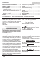
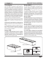
Hatco Remote Refrigerated Drop-In Wells are specially
designed to hold cold foods at safe serving temperatures. The
insulated, top-mount units are available in one through six pan
configurations. A unique top bezel design allows cold air to
effectively blanket the food product inside the refrigerated well.
In addition, the bezel design provides clear viewing and easy
access to the food contents of the refrigerated well.
The components of the Remote Refrigerated Drop-In Well are
shipped as separate pieces that require field installation and
connection. This provides the end user greater installation
flexibility than self-contained units. The components include a
refrigerated well, a Control Box, and a condensing unit (CWBR
and CWBR-S Models). For installations that already have an
appropriate condensing unit, Remote Refrigerated Drop-In
Wells are available with the refrigerated well and Control Box
only (CWBX and CWBX-S Models). One year parts and on-site
labor warranty is standard.
Hatco Remote Refrigerated Drop-In Wells are a product of
extensive research and field testing. The materials used were
selected for maximum durability, attractive appearance, and
optimum performance. Every unit is inspected and tested
thoroughly prior to shipment.
This manual provides the installation, safety, and operating
instructions for Remote Refrigerated Drop-In Wells. Hatco
recommends all installation, operating, and safety instructions
appearing in this manual be read prior to installation or
operation of a unit.
WARNING
WARNING indicates a hazardous situation which, if not
avoided, could result in death or serious injury.
CAUTION
CAUTION indicates a hazardous situation which, if not
avoided, could result in minor or moderate injury.
NOTICE
NOTICE is used to address practices not related to
personal injury.
Record the model number, serial number, voltage, and
purchase date of the unit in the spaces below (specification
labels located on the Control Box, well enclosure, and
condensing unit, if equipped). Please have this information
available when calling Hatco for service assistance.
Model No. ________________________________________
Serial No. _________________________________________
Voltage ___________________________________________
Date of Purchase ___________________________________
Register your unit!
Completing online warranty registration will prevent delay in
obtaining warranty coverage. Access the Hatco website at
www.hatcocorp.com, select the Support pull-down menu,
and click on “Warranty”.
Business
Hours: 7:00 to 5:00 Monday–Friday,
Central Time (CT)
(Summer Hours — June to September:
7:00 to 5:00 Monday–Thursday
7:00 to 4:00 Friday)
Telephone: 800-558-0607; 414-671-6350
E-mail: [email protected]
24 Hour 7 Day Parts and Service
Assistance available in the United States
and Canada by calling 800-558-0607.
Additional information can be found by visiting our web site at
www.hatcocorp.com.
IMPORTANT SAFETY INFORMATION

Form No. CWBRM-0220
3
English
IMPORTANT SAFETY INFORMATION
WARNING
ELECTRIC SHOCK HAZARD:
• Units supplied without an electrical cord and plug
require a hardwired connection to on-site electrical
system. Connection must be properly grounded and
of correct voltage, size, and configuration for electrical
specifications of unit. Contact a qualified electrician to
determine and install proper electrical connection.
• Unit must be installed by qualified, trained installers.
Installation must conform to all local electrical and
plumbing codes. Installation by unqualified personnel
will void the unit warranty and may lead to electric
shock or burn, as well as damage to unit and/or its
surroundings. Check with local plumbing and electrical
inspectors for proper procedures and codes.
• Turn OFF power switch and disconnect unit from power
source before performing any cleaning, adjustments,
or maintenance.
• Unit is not weatherproof. Locate unit indoors.
• DO NOT submerge or saturate with water. Unit is not
waterproof. Do not operate if unit has been submerged
or saturated with water.
• This unit is not “jet-proof” construction. Do not use
jet-clean spray to clean this unit.
• Do not steam clean or use excessive water on unit.
• This unit must be serviced by qualified personnel only.
Service by unqualified personnel may lead to electric
shock or burn.
• Use only Genuine Hatco Replacement Parts when
service is required. Failure to use Genuine Hatco
Replacement Parts will void all warranties and may
subject operators of the equipment to hazardous
electrical voltage, resulting in electrical shock or burn.
Genuine Hatco Replacement Parts are specified to
operate safely in the environments in which they are
used. Some aftermarket or generic replacement parts
do not have the characteristics that will allow them to
operate safely in Hatco equipment.
FIRE HAZARD:
• Installcondensingunitwithaminimumof6″(152mm)
of space between all sides of unit and any combustible
surfaces.
• Do not use flammable cleaning solutions to clean this unit.
EXPLOSION HAZARD: Do nqot store or use gasoline or
other flammable vapors or liquids in the vicinity of this or
any other appliance.
This unit must be installed by qualified, trained installers.
Installation must conform to all local electrical and
plumbing codes. Check with local plumbing and electrical
inspectors for proper procedures and codes.
Make sure food product and food pans have been chilled
to the proper food-safe temperature before placing in
unit. Failure to cool food product properly may result in
serious health risks. This unit is for holding pre-chilled
food product only.
Make sure all operators have been instructed on the safe
and proper use of the unit.
WARNING
Hatco Corporation is not responsible for actual food
product serving temperature. It is the responsibility of the
user to ensure that food product is held and served at a
safe temperature.
This unit is not intended for use by children or persons
with reduced physical, sensory, or mental capabilities.
Ensure proper supervision of children and keep them
away from the unit.
Maintain proper cleanliness of the unit. Proper cleanliness
and sanitation is critical for food-safe operation. Refer to
MAINTENANCE section for cleaning procedures.
This unit has no “user-serviceable” parts. If service
is required on this unit, contact an Authorized Hatco
Service Agent or contact the Hatco Service Department at
800-558-0607 or 414-671-6350.
CAUTION
Locate unit at the proper counter height in an area that is
convenient for use. Location should be level and strong
enough to support weight of unit and contents.
NOTICE
This unit is designed for use in environments where ambient
temperature is between 65°F (18°C) and 86°F (30°C).
When shipped during cold weather months, store unit in
proper ambient temperature environment for 10 hours to
prevent compressor and/or refrigerant line damage. If unit
is turned on and there is excessive noise and vibration,
turn off immediately and allow additional warm up time.
Provide louvered or grill-style openings with a minimum
sizeof12″x12″/144squareinches(31x31cm/961sqcm)
in the cabinetry in front of and behind the condensing unit
for proper ventilation. Failure to provide adequate air flow
through the condensing unit may cause unit failure and
will void the unit warranty.
Transport and install unit in upright position only. Failure
to do so may result in damage to the refrigeration system.
Use caution and avoid hitting condensing unit hoses/lines
when installing unit. Damage caused during installation is
not covered under warranty.
Do not locate unit in an area subject to excessive
temperatures or grease from grills, fryers, etc. Excessive
temperatures could cause damage to unit.
Clean unit daily to avoid malfunctions and maintain
sanitary operation.
Use non-abrasive cleaners and cloths only. Abrasive cleaners
and cloths could scratch the finish of the unit, marring its
appearance and making it susceptible to soil accumulation.
Do not use steel wool for cleaning. Steel wool will scratch
the finish.
Do not use harsh chemicals such as bleach, cleaners
containing bleach, or oven cleaners to clean the unit.
This unit is intended for commercial use only—NOT for
household use.
Read the following important safety information before using this equipment to avoid serious
injury or death and to avoid damage to equipment or property.

4
Form No. CWBRM-0220
English
MODEL DESCRIPTION
All Models
Hatco Remote Refrigerated Drop-In Wells are reliable and
versatile. Each unit has an insulated, stainless steel and
aluminized steel housing. The sides of the internal well are
completely surrounded with a copper evaporator coil to provide
even cooling from top to bottom. The Remote Refrigerated
Drop-In Well is controlled with a digital temperature controller
and a Power I/O (on/off) Switch housed in a single, remote-
mounted Control Box. All models are designed to be mounted
to the topside of various types of countertop material including
stainless steel, wood, Corian, Swanstone, etc... Hatco
Refrigerated Drop-In Wells are designed, manufactured, and
tested to maintain safe food holding temperatures.
Each model is supplied from the factory with the appropriate
depending on the model’s pan capacity.
Each individual well is capable of holding a variety of pan
combinations of full size, 1/2-size, 1/3-size, and/or 1/6-size
pans with accessory Adapter Bars.
Food Pans, Pan Support Bars, Adapter Bars, and other
accessories are available for the Remote Refrigerated Drop-In
Wells. Refer to the OPTIONS AND ACCESSORIES section in
this manual for details.
CWBR Models
CWBR models consist of a refrigerated well, a remote-mounted
Control Box, a remote-mounted condensing unit, and a thermal
expansion valve (TXV valve, shipped loose). All plumbing and
electrical connections between the components as well as to
the electrical supply are the responsibility of the end user and
a qualified installer.
CWBR-S Models
CWBR-S models are available in one, two, three, and four pan
configurations. These models are “slim” designed and orient
full-size sheet pans with the long side facing the customer. The
slim design allows easy, reachable access to everything on the
unit.
CWBR-S models consist of a refrigerated well, a remote-
mounted Control Box, a remote-mounted condensing unit,
and a thermal expansion valve (TXV valve, shipped loose). All
plumbing and electrical connections between the components
as well as to the electrical supply are the responsibility of the
end user and a qualified installer.
CWBX Models
CWBX models consist of a refrigerated well with a solenoid
valve, a remote-mounted Control Box, and a thermal expansion
valve (TXV valve, shipped loose). These components must
be connected to an end user-supplied condensing unit. All
plumbing and electrical connections between the components
as well as to the electrical supply are the responsibility of the
end user and a qualified installer.
CWBX-S Models
CWBX-S models are available in one, two, three, and four pan
configurations. These models are “slim” designed and orient full-
size sheet pans with the long side facing the customer. The slim
design allows easy, reachable access to everything on the unit.
CWBX-S models consist of a refrigerated well with a solenoid
valve, a remote-mounted Control Box, and a thermal expansion
valve (TXV valve, shipped loose). These components must
be connected to an end user-supplied condensing unit. All
plumbing and electrical connections between the components
as well as to the electrical supply are the responsibility of the
end user and a qualified installer.
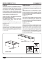
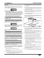
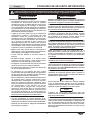
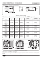
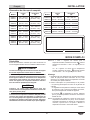
CWBR-3/CWBX-3
Condensing Unit
(CWBR and CWBR-S
Models only)
Control Panel
(All Models)
TXV Valve
(All Models)
Pans Not Included
CWBR-S3/CWBX-S3

Form No. CWBRM-0220
5
English
Volts Hertz Watts Amps
120 50/60 12 0.1
220/230/240 50/60 17 0.1
SPECIFICATIONS
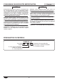
MODEL DESIGNATION
C W B R - x 1
Cold Well
Built-In
R = w/Remote Condensing Unit
X = Well Only
No Character = Standard Depth
S = Slim Depth
Full-Size Pan Capacity
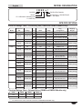
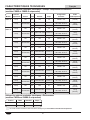
Electrical Ratings Chart—Condensing Unit (CWBR and CWBR-S Models only)
Electrical Ratings Chart—Solenoid Valve (CWBX and CWBX-S Models only)
The shaded areas contain electrical information for International models only.
Model
Compressor
Size Voltage Hertz Watts Amps
Plug
Configuration
Shipping
Weight
CWBR-1
CWBR-S1
1/5 hp 120 60 300 3.8 NEMA 5-15P 133 lbs. (60 kg)
1/3 hp 220–230–240
50 1089–1190–1296 5.0–5.2–5.4
CEE 7/7 Schuko,
BS-1363, AS 3112
133 lbs. (60 kg)
60 1129–1234–1344 5.1–5.4–5.6 CEE 7/7 Schuko, BS-1363
CWBR-2
CWBR-S2
1/5 hp 120 60 300 3.8 NEMA 5-15P 175 lbs. (79 kg)
1/3 hp 220–230–240
50 1089–1190–1296 5.0–5.2–5.4
CEE 7/7 Schuko,
BS-1363, AS 3112
175 lbs. (79 kg)
60 1129–1234–1344 5.1–5.4–5.6 CEE 7/7 Schuko, BS-1363
CWBR-3 1/5 hp 120 60 300 3.8 NEMA 5-15P 213 lbs. (97 kg)
1/3 hp 220–230–240
50 1089–1190–1296 5.0–5.2–5.4
CEE 7/7 Schuko,
BS-1363, AS 3112
213 lbs. (97 kg)
60 1129–1234–1344 5.1–5.4–5.6 CEE 7/7 Schuko, BS-1363
CWBR-S3 1/3 hp 120 60 450 5.9 NEMA 5-15P 213 lbs. (97 kg)
3/8 hp
220–230–240
50 826–904–984 3.8–3.9–4.1
CEE 7/7 Schuko,
BS-1363, AS 3112
213 lbs. (97 kg)
1/3 hp 60 1129–1234–1344 5.1–5.4–5.6 CEE 7/7 Schuko, BS-1363
CWBR-4 1/3 hp 120 60 450 5.9 NEMA 5-15P 235 lbs. (107 kg)
3/8 hp
220–230–240
50 826–904–984 3.8–3.9–4.1
CEE 7/7 Schuko,
BS-1363, AS 3112
235 lbs. (107 kg)
1/3 hp 60 1129–1234–1344 5.1–5.4–5.6 CEE 7/7 Schuko, BS-1363
CWBR-S4 5/8 hp 120 60 800 8.7 NEMA 5-15P 235 lbs. (107 kg)
1/2 hp
220–230–240
50 826–904–984 3.8–3.9–4.1
CEE 7/7 Schuko,
BS-1363, AS 3112
235 lbs. (107 kg)
5/8 hp 60 1956–2138–2328 8.9–9.3–9.7 CEE 7/7 Schuko, BS-1363
CWBR-5 5/8 hp 120 60 800 8.7 NEMA 5-15P 270 lbs. (122 kg)
1/2 hp
220–230–240
50 826–904–984 3.8–3.9–4.1
CEE 7/7 Schuko,
BS-1363, AS 3112
270 lbs. (122 kg)
5/8 hp 60 1956–2138–2328 8.9–9.3–9.7 CEE 7/7 Schuko, BS-1363
CWBR-6 5/8 hp 120 60 800 8.7 NEMA 5-15P 313 lbs. (142 kg)
1/2 hp
220–230–240
50 826–904–984 3.8–3.9–4.1
CEE 7/7 Schuko,
BS-1363, AS 3112
313 lbs. (142 kg)
5/8 hp 60 1956–2138–2328 8.9–9.3–9.7 CEE 7/7 Schuko, BS-1363

6
Form No. CWBRM-0220
English
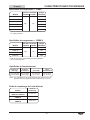
Model
Width
(A)
Depth
(B)
Overall
Height
(C)
Well
Height
(D)
CWBR-1
19
(483 mm)
27
(686 mm)
17
(433 mm)
12
(305 mm)
CWBX-1
CWBR-2
32
(813 mm)
27
(686 mm)
17
(433 mm)
12
(305 mm)
CWBX-2
CWBR-3
45
(1143 mm)
27
(686 mm)
17
(433 mm)
12
(305 mm)
CWBX-3
Model
Width
(A)
Depth
(B)
Overall
Height
(C)
Well
Height
(D)
CWBR-4
58
(1473 mm)
27
(686 mm)
17
(433 mm)
12
(305 mm)
CWBX-4
CWBR-5
71
(1803 mm)
27
(686 mm)
17
(433 mm)
12
(305 mm)
CWBX-5
CWBR-6
84
(2134 mm)
27
(686 mm)
17
(433 mm)
12
(305 mm)
CWBX-6
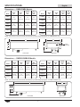
SPECIFICATIONS
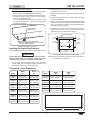
Dimensions — CWBR/CWBX Models
A
D
B
C
2-3/4″
(70 mm)
Front View Side View
NOTE: The solenoid valve and bracket dimensioned by Overall Height (D) appear on CWBX Models only.
Model
Width
(A)
Depth
(B)
Overall
Height
(C)
Well
Height (D)
CWBR-S1
27-1/16
(687 mm)
19
(481 mm)
17-1/8
(435 mm)
12
(305 mm)
CWBX-S1
CWBR-S2
48-1/8
(1222 mm)
19
(481 mm)
17-1/8
(435 mm)
12
(305 mm)
CWBX-S2
Model
Width
(A)
Depth
(B)
Overall
Height
(C)
Well
Height (D)
CWBR-S3
69-3/16
(1757 mm)
19
(481 mm)
17-1/8
(435 mm)
12
(305 mm)
CWBX-S3
CWBR-S4
90-1/4
(2292 mm)
19
(481 mm)
17-1/8
(435 mm)
12
(305 mm)
CWBX-S4
Dimensions — CWBR-S/CWBX-S Models
Front View Side View
A
B
D
C
NOTE: The solenoid valve and bracket dimensioned by Overall Height (D) appear on CWBX-S Models only.

Form No. CWBRM-0220
7
English
Model
Width
(A)
Depth
(B)
Height
(C)
Mounting Hole
Width (D)
Mounting Hole
Depth (E)
CWBR-1
CWBR-S1
CWBR-2
CWBR-S2
CWBR-3
14-5/8
(371 mm)
12-1/4
(312 mm)
11-3/8
(289 mm)
6-1/2
(165 mm)
9-1/2
(242 mm)
CWBR-S3
CWBR-4
14-1/2
(369 mm)
12-1/4
(312 mm)
11-3/8
(289 mm)
6-1/2
(165 mm)
9-1/2
(242 mm)
120 V, 60 Hz
CWBR-S4
CWBR-5
CWBR-6
17-1/2
(444 mm)
16-3/8
(415 mm)
12-1/8
(306 mm)
9-1/4
(235 mm)
11-1/4
(286 mm)
220-230-240 V, 60 Hz
CWBR-S4
CWBR-5
CWBR-6
18-7/8
(479 mm)
16-3/8
(415 mm)
11-7/8
(300 mm)
9-1/4
(235 mm)
11-1/4
(286 mm)
220-230-240 V, 50 Hz
CWBR-S4
CWBR-5
CWBR-6
16-1/2
(420 mm)
13
(331 mm)
12-1/8
(306 mm)
9-1/4
(235 mm)
11-1/4
(286 mm)
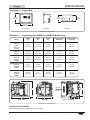
SPECIFICATIONS
Dimensions — Control Box
8-3/16″
(208 mm)
4-1/8″
(105 mm)
4-1/2″
(113 mm)
6-1/2″
(165 mm)
Front ViewTop ViewSide View
Dimensions — Control Box
Dimensions — Condensing Unit (CWBR and CWBR-S Models only)
Top ViewFront View Side View
C
A
B
3X Ø 0.375
(10 mm)
D
E
Air Flow
Dimensions — Condensing Unit
Refrigerant Information
Hatco Refrigerated Drop-In Wells use R-513A refrigerant.

8
Form No. CWBRM-0220
English
Line Size* Load
Model Suction Liquid BTU/Hour
CWBX-1
3/8 1/4
330
CWBX-2 630
CWBX-3 930
CWBX-4 1230
CWBX-5 1530
CWBX-6 1830
Compressor Specifications — CWBX
* Recommended line size for installations of 50’ or less.
Line Size* Load
Model Suction Liquid BTU/Hour
CWBX-S1
3/8 1/4
330
CWBX-S2 730
CWBX-S3 1130
CWBX-S4 1530
Compressor Specifications — CWBX-S
* Recommended line size for installations of 50’ or less.
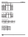
SPECIFICATIONS
Discharge
Pressure
Suction
Pressure Superheat Subcooling
115 to 125 psig
(7.9 to 8.6 bar)
6 to 9 psig
(0.4 to 0.6 bar)
4° to 10°F
(2.2° to 5.6°C)
5° to 10°F
(2.8° to 5.6°C)
Operating Specifications
Remote Unit Fill Weights
NOTE: The Operating Specifications are accurate for units in an ambient
air temperature of 75°F (24°C).
Models Fill Weights
CWBR-1, CWBR-4
CWBR-S1, CWBR-S3
1 lb 15 oz
CWBR-2, CWBR-3
CWBR-S2
2 lbs 1 oz
CWBR-5, CWBR-6
CWBR-S4
2 lbs 13 oz

Form No. CWBRM-0220
9
English
INSTALLATION
General
Remote Refrigerated Drop-In Wells are shipped from the
factory as components that require installation and connection.
Use the following procedures to install each component and
make the appropriate connections.
WARNING
ELECTRIC SHOCK HAZARD:
• Units supplied without an electrical cord and plug
require a hardwired connection to on-site electrical
system. Connection must be properly grounded and
of correct voltage, size, and configuration for electrical
specifications of unit. Contact a qualified electrician to
determine and install proper electrical connection.
• Unit is not weatherproof. Locate unit indoors.
FIRE HAZARD: Install condensing unit with a minimum of
6″(152mm)ofspacebetweenallsidesoftheunitandany
combustible surfaces.
This unit must be installed by qualified, trained installers.
Installation must conform to all local electrical and
plumbing codes. Check with local plumbing and electrical
inspectors for proper procedures and codes.
CAUTION
Locate unit at the proper counter height in an area that is
convenient for use. Location should be level and strong
enough to support weight of unit and contents.
NOTICE
This unit is designed for use in environments where
ambient temperature is between 65°F (18°C) and 86°F
(30°C).
When shipped during cold weather months, store unit in
proper ambient temperature environment for 10 hours to
prevent compressor and/or refrigerant line damage. If unit
is turned on and there is excessive noise and vibration,
turn off immediately and allow additional warm up time.
Provide louvered or grill-style openings with a minimum
size of 12″ x 12″/144 square inches (31 x 31 cm/
961 square cm) in the cabinetry in front of and behind the
condensing unit for proper ventilation. Failure to provide
adequate air flow through the condensing unit may cause
unit failure and will void the unit warranty.
Transport and install unit in upright position only. Failure
to do so may result in damage to the refrigeration system.
Do not locate unit in an area subject to excessive
temperatures or grease from grills, fryers, etc. Excessive
temperatures could cause damage to unit.
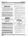
All Refrigerated Drop-In Wells are shipped in a shipping frame
for protection and stability. Keep the unit in the shipping frame
until the unit and the installation site are completely prepared
for the unit to be installed.
1. Remove all external packaging from the unit.
2. Remove tape, protective packaging, and literature from all
surfaces of unit.
NOTE: To prevent delay in obtaining warranty coverage, complete
online warranty registration. See the IMPORTANT
OWNER INFORMATION section for details.
3. Cut the appropriate opening in the countertop for the unit
being installed. Refer to “Countertop Cutout Dimensions”
in this section.
4. Cut and drill the appropriate holes in the vertical surface
where the Control Box will be installed. Refer to the
“Installing the Control Box” procedure in this section for
cutout and hole dimensions.
5. Make structural modifications or add bracing underneath
the countertop to ensure the countertop will support the
weight of the unit and its contents.
NOTE: The countertop must be level to ensure proper draining
of the refrigerated well.
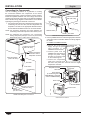
6. Lift the unit out of the shipping frame and carefully lower it
into the countertop cutout. This step requires two or more
people, depending on the unit.
Countertop
Coutout
Refrigerated
Well
Installing a CWBR-3/CWBX-3 Model
7. Apply National Sanitation Foundation-approved (NSF-
approved) silicone sealant around the edge of the unit to
seal it to the countertop.
trap and drain line are not available, a catch pan (not
supplied) must be used under the drain fitting to contain
water draining from the well enclosure.
NOTE: Consult a qualified plumber for proper trap and drain
installation that conforms to local plumbing codes.
9. Install the Control Box in the desired location. Refer to the
“Installing the Control Box” procedure in this section.
10. For CWBR and CWBR-S Models, install the condensing
unit in the desired location. Refer to the SPECIFICATION
section for installation dimensions.
• Make sure the installation site offers continuous air flow
ventilation to the condensing unit.
between all sides of the condensing unit and any
combustible surface.
11. Have qualified installers perform the “Connecting the
Components” procedure in this section.
12. Clean the well enclosure thoroughly in preparation for
initial operation. Refer to the MAINTENANCE section for
proper cleaning procedures.
NOTE: If a catch pan is used underneath the drain fitting, make
sure the pan is emptied regularly to prevent over-flowing.

10
Form No. CWBRM-0220
English
INSTALLATION
Connecting the Components
Use the following procedure as a guideline for making
the connections between the components of the remote
refrigerated well system. These connections must be made by
trained and qualified installers and must comply with all local
plumbing and electrical codes. Refer to the SPECIFICATIONS
section and the wiring diagram included with the unit for details
regarding the plumbing and electrical connections.
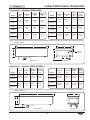
1. Connect the liquid and suction refrigerant lines between the
condensing unit, the TXV valve, and the refrigerated well
evaporator coil. Refer to the appropriate illustration below
and the SPECIFICATIONS section for connection details.
NOTE: The maximum refrigerant line length between the
condensing unit and the evaporator coil is 50 feet (15 m).
NOTE: For refrigerant line connections, use a self-fluxing
brazing compound (example = Sil-Fos 5
®
) at a brazing
temperature range of 1300–1500°F (704–816°C).
Liquid
Connection
(1/4″ O.D. tube)
Liquid Connection
(3/8″ O.D. tube)
Condensing
Unit
Well
TXV Valve
Suction Connection
(3/8″ O.D. tube)
TXV Bulb
Fasten TXV bulb to
the suction side of
evaporator coil here.
Suction Connection
(3/8″ O.D. tube)
Suction Connection
(3/8″ O.D. tube)
CWBR Model Refrigerant Connections
Liquid Connection
(3/8″ O.D. tube)
Well
TXV Valve
Suction Connection
(3/8″ O.D. tube)
Suction Connection
(3/8″ O.D. tube)
Solenoid Valve
From
Condensing
Unit
To Condensing
Unit
CWBX Model Refrigerant Connections
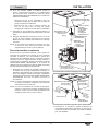
2. Have a qualified electrician make the appropriate electrical
connections to the Control Box. Refer to the wiring diagram
for details.
For CWBR and CWBR-S Models:
Condensing Unit
Power Input
a. Connect the on-site power
supply through the power
input knockout to the
POWER IN terminal block.
b. Connect power from the
POWER OUT terminal block,
through the power output
knockout, to the power input
on the condensing unit.
c. Connect the temperature
probe wire connector from
the well to the probe wire connector from the digital
temperature controller.
Power Input
Power Output
(to condensing unit on
CWBR Models or solenoid
valve on CWBX Models)
Temperature Probe
Wire Inlet
Terminal Blocks
Digital Temperature
Controller
Access Cover
Control Box Connections

Form No. CWBRM-0220
11
English
Model
Width
(A)
Depth
(B)
CWBR-S1
CWBX-S1
25-1/426-1/16
(641 – 662 mm)
17-1/1617-15/16
(433–456 mm)
CWBR-S2
CWBX-S2
46-1/447-15/16
(1175 – 1196 mm)
17-1/1617-15/16
(433 – 456 mm)
CWBR-S3
CWBX-S3
67-5/1668-1/8
(1710 – 1731 mm)
17-1/1617-15/16
(433 – 456 mm)
CWBR-S4
CWBX-S4
88-3/889-1/4
(2245 – 2266 mm)
17-1/1617-15/16
(433 – 456 mm)
Model
Width
(A)
Depth
(B)
CWBR-1
CWBX-1
17-1/818
(435 – 457 mm)
25-3/1626
(640 – 660 mm)
CWBR-2
CWBX-2
30-1/831
(765 – 787 mm)
25-3/1626
(640 – 660 mm)
CWBR-3
CWBX-3
43-1/844
(1095 – 1118 mm)
25-3/1626
(640 – 660 mm)
CWBR-4
CWBX-4
56-1/857
(1425 – 1448 mm)
25-3/1626
(640 – 660 mm)
CWBR-5
CWBX-5
69-1/870
(1756 – 1778 mm)
25-3/1626
(640 – 660 mm)
CWBR-6
CWBX-6
82-1/883
(2086 – 2108 mm)
25-3/1626
(640 – 660 mm)
INSTALLATION
B
A
Countertop Cutout Dimensions
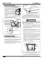
For CWBX and CWBX-S Models:
a. Connect the on-site power supply through the power
input knockout to the POWER IN terminal block.
b. Connect power from the POWER OUT terminal block,
through the power output knockout, to the solenoid
valve on the refrigerated well.
c. Connect the temperature probe wire connector from
the well to the probe wire connector from the digital
temperature controller.
Solenoid Valve
Power Input
Temperature probe installed here.
Wire from probe connects to control panel
(same for CWBR Models).
CWBX Model Electrical Connections
Installing the Control Box Remotely
Use the following procedure to install the control box remotely.
WARNING
Control Box must be mounted in a vertical surface.
Mounting Control Box in a horizontal surface may result
in the collection of liquids and lead to electric shock.
1. Cut and drill the appropriate holes in the mounting
surface. Refer to the “Control Box Cutout and Screw Hole
Dimensions” chart for the cutout dimensions.
2. Remove the four trim cover screws from the control box
and remove the trim cover.
3. Position the control box into the cutout opening through the
backside.
4. Fasten the control box to the vertical surface using four
screws (not supplied).
where the trim cover will contact the cabinet surface. Refer
to the “Control Box Cutout and Screw Hole Dimensions”
illustration for more information.
6. Reinstall the trim cover on the control box and secure in
position using the four trim cover screws. Make sure to
embed the trim cover edge into the silicone.
7/16″
(11 mm)
3/8″
(9 mm)
Silicone Sealant
5-5/8″
(143 mm)
7-7/16″
(189 mm)
7-3/4″
(196 mm)
3-1/2″
(89 mm)
1-1/16″
(27 mm)
Control Box Cutout and Screw Hole Dimensions
NOTE: Make sure the width of the Control Box cutout does not
exceed the above dimension.

12
Form No. CWBRM-0220
English
OPERATION
General
Use the following procedures to operate the Remote
Refrigerated Drop-In Wells.
WARNING
Read all safety messages in the Important Safety
Information section before operating this equipment.
Make sure food product has been chilled to the proper
food-safe temperature before placing in the unit. Failure
to cool food product properly may result in serious health
risks. This unit is for holding pre-chilled food product only.
NOTICE
This unit is designed for use in environments where
ambient temperature is between 65°F (18°C) and 86°F
(30°C).
When shipped during cold weather months, store unit in
proper ambient temperature environment for 10 hours to
prevent compressor and/or refrigerant line damage. If unit
is turned on and there is excessive noise and vibration, turn
off immediately and allow additional warm up time.
NOTE: If the display flashes “OFF” and then the current
temperature, press and hold the key for three
seconds. The display will no longer flash “OFF”.
If the display flashes “df” and then the current
temperature, press and hold the key for three
seconds. The display will no longer flash “df”.
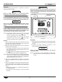
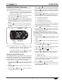
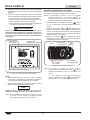
Startup
1. Fill the refrigerated well with empty food pans. The well
will chill to the setpoint temperature more quickly and
efficiently with empty pans in the well.
2. Move the Power I/O (on/off) Switch to the I (on) position
(located on the Control Box).
• The digital temperature controller will energize and
“ON” will appear on the display, followed by the current
temperature of the unit.
• The symbol on the display will illuminate to show
the condensing unit is active and chilling the well.
NOTE: The unit is pre-set at the factory to a setpoint temperature
of 32°F (0°C). If ambient conditions require adjustment
to the setpoint temperature, refer to the “Changing the
Setpoint Temperature” in this section.
3. Allow the unit approximately 30 minutes to reach the
setpoint temperature before loading pre-chilled food
product.
4. Verify on the display that the unit has reached the proper
setpoint temperature, and replace the empty pans in
the well with pans that are loaded with pre-chilled food
product.
• Always use a food pan. Do not place food directly into
the refrigerated well.
• Stir thick food items frequently to keep food chilled
uniformly.
WARNING
Hatco Corporation is not responsible for the actual food
product serving temperature. It is the responsibility of the
user to ensure that the food product is held and served at
a safe temperature.
Digital Temperature
Controller
Power I/O (on/off) Switch
Unit “Active”
Symbol
Control Box
Shutdown
1. Move the Power I/O (on/off) Switch to the O (off) position.
The digital temperature controller and condensing unit will
shut off.
2. Perform the “Daily Cleaning” procedure in the
MAINTENANCE section of this manual.
NOTICE
Clean unit daily to avoid malfunctions and maintain
sanitary operation.
NOTE: If a catch pan is used underneath the drain fitting,
make sure the pan is emptied regularly to prevent over-
flowing.

Form No. CWBRM-0220
13
English
OPERATION
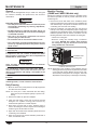
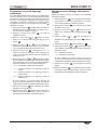
Changing the Setpoint Temperature
Use the following procedure to change the setpoint temperature
on the digital temperature controller.
NOTE: Changes to the setpoint temperature should be made
in small increments (1 to 2 degrees). Wait at least two
hours after a change in setpoint temperature before
checking for the desired result.
1. Press and hold the key for one second until the
display flashes the current setpoint temperature.
2. Press the or key to increase or decrease the
setpoint temperature. If no key is pressed within 60
seconds, the display will revert to normal operation and
the current temperature of the unit will be shown on the
display.
3. Press the key to lock in the new setpoint temperature.
The display will revert to show the current temperature of
the unit.
Display
Down Arrow/
Defrost Key
Unit
“Active”
Symbol
Up Arrow/
Standby Key
SET
Key
Digital Temperature Controller
NOTE: If the display flashes “OFF” and then the current
temperature, press and hold the key for three
seconds. The display will no longer flash “OFF”.
If the display flashes “df” and then the current
temperature, press and hold the key for three
seconds. The display will no longer flash “df”.
Setting the Auto-Defrost Cycle
Hatco Refrigerated Wells are programmed at the factory with
the auto-defrost cycle deactivated. Use the following procedure
to activate the auto-defrost cycle if ambient or operational
conditions require the unit to defrost occasionally. When the
unit is in a defrost cycle, will appear on the display.
1. Press and hold the key for three seconds to access
programming mode. “PS” (password) will appear on the
display.
2. Press the key again. A numeric value will appear on
the display.
3. Press the or key until the number “22” appears
on the display, then press the key.
4. Use the or key to scroll through the programmable
parameters until “dI” (defrost interval) appears on the display.
5. Press the key to select “dI”. The current number of
defrost cycles will be shown on the display. For new units,
this value will be “0”.
6. Press the or key within 60 seconds to scroll to
the desired number of hours between defrost cycles. See
below for examples of how the defrost cycle(s) operate:
“0” = auto-defrost is deactivated
“1” = unit will defrost every hour
“4” = unit will defrost every four hours
“12” = unit will defrost every twelve hours
If no key is pressed within 60 seconds, the display will
revert to normal operation and the current temperature of
the unit will be shown on the display.
7. Press the key to lock in the new defrost cycle setting.
8. Press and hold the key for three seconds to exit
programming mode. The display will revert to show the
current temperature of the unit.
Changing Fahrenheit and Celsius Setting
Use the following procedure to change between Fahrenheit and
Celsius on the display.
1. Press and hold the key for three seconds to access
programming mode. “PS” (password) will appear on the
display.
2. Press the key again. A numeric value will appear on
the display.
3. Press the or key until the number “22” appears
on the display, then press the key.
4. Use the or key to scroll through the programmable
parameters until appears on the display.
5. Press the key to select .
6. Press the or key within 60 seconds to scroll to
the desired setting. See below for the correct setting:
“0” = Displays Celsius
“1” = Displays Fahrenheit
If no key is pressed within 60 seconds, the display will
revert to normal operation and the current temperature of
the unit will be shown on the display.
7. Press the key to lock in the new setting.
8. Press and hold the key for three seconds to exit
programming mode. The display will revert to show the
current temperature of the unit.

14
Form No. CWBRM-0220
English
MAINTENANCE
General
Hatco Remote Refrigerated Drop-In Wells are designed
for maximum durability and performance, with minimum
maintenance.
WARNING
ELECTRIC SHOCK HAZARD:
• Turn OFF power switch and disconnect unit from power
source before performing any cleaning, adjustments,
or maintenance.
• DO NOT submerge or saturate with water. Unit is not
waterproof. Do not operate if unit has been submerged
or saturated with water.
• This unit is not “jet-proof” construction. Do not use
jet-clean spray to clean this unit.
• Do not steam clean or use excessive water on unit.
• This unit must be serviced by qualified personnel only.
Service by unqualified personnel may lead to electric
shock or burn.
FIRE HAZARD: Do not use flammable cleaning solutions
to clean this unit.
This unit has no “user-serviceable” parts. If service
is required on this unit, contact an Authorized Hatco
Service Agent or contact the Hatco Service Department at
800-558-0607 or 414-671-6350.
NOTICE
Clean unit daily to avoid malfunctions and maintain
sanitary operation.
Use non-abrasive cleaners and cloths only. Abrasive
cleaners and cloths could scratch the finish of the unit,
marring its appearance and making it susceptible to soil
accumulation.
Do not use steel wool for cleaning. Steel wool will scratch
the finish.
Do not use harsh chemicals such as bleach, cleaners
containing bleach, or oven cleaners to clean the unit.
Daily Cleaning
1. Move the Power I/O (on/off) Switch to the O (off) position
and allow the unit to defrost.
NOTE: If a catch pan is used underneath the drain fitting,
make sure the pan is emptied regularly to prevent over-
flowing.
2. Remove and wash any pans and adapters.
3. Clean the wells using a clean cloth or sponge and mild
detergent. Use a plastic scouring pad to remove any
hardened food particles or mineral deposits.
4. Wipe down the wells with a clean, sanitized cloth to
remove the detergent residue. Repeat until all detergent
residue is gone and the wells are clean.
5. Wipe down the outside of the ventilation panels where the
condensing unit is installed.
6. Wipe dry the entire unit and the ventilation panels with a
clean, non-abrasive cloth.
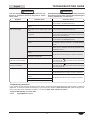
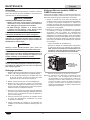
Monthly Cleaning
(CWBR and CWBR-S Models only)
Perform the following procedure monthly to maintain proper
and efficient operation as well as prevent malfunction of the
condensing unit.
1. Remove and clean both sides of the ventilation panels
that are located where the condensing unit is installed. Dirt
and dust build-up in the panels can restrict air flow to the
condensing unit and cause over-heating.
2. Clean the condenser coil cooling fins. Dirt, dust, and lint
build-up in the cooling fins will prevent proper cooling of the
refrigerant in the refrigeration system. This buildup will cause
inefficient operation and can lead to unit failure. Use the
following methods to clean the condenser coil cooling fins:
• Vacuum the cooling fins.
• Brush the cooling fins vertically using a condenser
coil brush. NOTICE: Use caution when brushing
the cooling fins, they are delicate and can be bent
easily. DO NOT use a wire brush.
Condenser Coil
Cooling Fins
Condenser Coil Cooling Fins
NOTE: Depending on the conditions of the installation site, this
cleaning procedure may need to be performed more often
or less often than monthly. Monitor the level of dirt, dust,
and lint buildup on the panels and cooling fins, and make
adjustments to the frequency of cleanings as necessary.

Form No. CWBRM-0220
15
English
Symptom Probable Cause Corrective Action
Unit too cold. Setpoint temperature too low. Adjust the setpoint temperature to a higher setting. Refer to
the procedure in the OPERATION section.
Digital temperature controller not working
properly.
Contact Authorized Service Agent or Hatco for assistance.
Unit not cold enough. Food product not pre-chilled before loading
in unit.
Load unit with pre-chilled food product only.
Unit not filled with food pans/one or more open
pan positions.
Fill the refrigerated well with food pans. The well will chill
to the setpoint temperature more quickly and hold more
efficiently when filled with pans.
Setpoint temperature set too high. Adjust the setpoint temperature to a lower setting. Refer to
the procedure in the OPERATION section.
Condenser coil and/or ventilation panels are
plugged.
Clean the condenser coil and ventilation panels. Refer to
the “Monthly Cleaning” procedure in the MAINTENANCE
section.
Too much frost built up inside of unit. Turn off, defrost, and clean the unit. Activate an auto-
defrost cycle, if necessary (refer to the procedure in the
OPERATION section).
Digital temperature controller not working
properly.
Contact Authorized Service Agent or Hatco for assistance.
Refrigerant low/leaking or other internal
condensing unit malfunction.
Controller display flashes
“OFF” and unit is not working.
The unit is in Standby mode.
Press and hold the key for three seconds. The display
will no longer flash “OFF”.
Controller display flashes “df”
and unit is not working.
The unit is in Defrost mode.
Press and hold the key for three seconds. The display
will no longer flash “df”.
Unit not working. Unit turned off. Turn on unit.
Circuit breaker tripped. Reset circuit breaker. If circuit breaker continues to trip,
contact Authorized Service Agent or Hatco for assistance.
Digital temperature controller not working
properly.
Contact Authorized Service Agent or Hatco for assistance.
Condensing unit overheated.
Internal condensing unit malfunction.
TROUBLESHOOTING GUIDE
WARNING
This unit must be serviced by qualified personnel only.
Service by unqualified personnel may lead to electric
shock or burn.
WARNING
ELECTRIC SHOCK HAZARD: Turn OFF power switch and
disconnect unit from power source before performing any
cleaning, adjustments, or maintenance.
Troubleshooting Questions?
If you continue to have problems resolving an issue, please contact the nearest Authorized Hatco Service Agency or Hatco for
assistance. To locate the nearest Service Agency, log onto the Hatco website at www.hatcocorp.com, select the Support pull-
down menu, and click on “Find A Service Agent”; or contact the Hatco Parts and Service Team at:
Telephone: 800-558-0607 or 414-671-6350
e-mail: [email protected]

16
Form No. CWBRM-0220
English
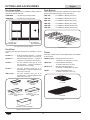
OPTIONS AND ACCESSORIES
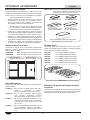
Pan Support Bars
Accessory pan support bars are available to divide wells into
sections for different size pans.
CWB12BAR ...........
CWB20BAR ...........
20″ (508 mm)
Pan Support Bar
12″ (305 mm)
Pan Support Bar
Pan Support Bars in Model CWB-3
Food Pans
Accessory stainless steel food pans are available in various
sizes.
ST PAN 1/3 ............
ST PAN 1/2 ............
ST PAN 2 ...............
ST PAN 4 ...............
(324 x 527 x 102 mm)
HDW6″PAN .........
(324 x 527 x 152 mm)
1/2 Pan1/3 Pan
Full Pan, 2-1/2″ (64 mm)
Deep
Full Pan, 4″ (102 mm)
Deep
Full Pan, 6″ (152 mm) Deep
Stainless Steel Food Pans
False Bottom
False bottoms are accessories available for all models. False
bottoms allow better drainage for units that hold ice.
CWB-1FB .............. For CWBR/X-1 Models (one piece)
CWB-2FB .............. For CWBR/X-2 Models (one piece)
CWB-3FB .............. For CWBR/X-3 Models (two pieces)
CWB-4FB .............. For CWBR/X-4 Models (two pieces)
CWB-5FB .............. For CWBR/X-5 Models (three pieces)
CWB-6FB .............. For CWBR/X-6 Models (three pieces)
CWB-2FB
CWB-1FB
False Bottoms
Trivets
Accessory stainless steel or nickel-plated trivets are available
in various sizes.
TRIVET (1/2)SS..... Half-size stainless steel trivet —
TRIVET SS ............ Full size stainless steel trivet —
TRIVET (1/2) ......... Half-size nickel-plated trivet —
TRIVET .................. Full size nickel-plated trivet —
1/2 Trivet
Full Trivet
Trivets

Form No. CWBRM-0220
17
English
OPTIONS AND ACCESSORIES
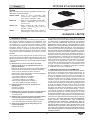
1. PRODUCT WARRANTY
Hatco warrants the products that it manufactures (the “Products”)
to be free from defects in materials and workmanship, under
normal use and service, for a period of one (1) year from the
date of purchase when installed and maintained in accordance
with Hatco’s written instructions or 18 months from the date
of shipment from Hatco. Buyer must establish the Product’s
purchase date by registering the Product with Hatco or by other
means satisfactory to Hatco in its sole discretion.
Hatco warrants the following Product components to be free
from defects in materials and workmanship from the date of
purchase (subject to the foregoing conditions) for the period(s)
of time and on the conditions listed below:
a) One (1) Year Parts and Labor PLUS One (1) Additional
Year Parts-Only Warranty:
Conveyor Toaster Elements (metal sheathed)
Drawer Warmer Elements (metal sheathed)
Drawer Warmer Drawer Rollers and Slides
Strip Heater Elements (metal sheathed)
Display Warmer Elements (metal sheathed air heating)
Holding Cabinet Elements (metal sheathed air heating)
Heated Well Elements — HW and HWB Series
(metal sheathed)
b) Two (2) Year Parts and Labor Warranty:
Induction Ranges
Induction Warmers
c) One (1) Year Parts and Labor PLUS Four (4) Years
Parts-Only Warranty:
3CS and FR Tanks
d) One (1) Year Parts and Labor PLUS Nine (9) Years
Parts-Only Warranty on:
Electric Booster Heater Tanks
Gas Booster Heater Tanks
e) Ninety (90) Day Parts-Only Warranty:
Replacement Parts
THE FOREGOING WARRANTIES ARE EXCLUSIVE AND
IN LIEU OF ANY OTHER WARRANTY, EXPRESSED OR
IMPLIED, INCLUDING BUT NOT LIMITED TO ANY IMPLIED
WARRANTY OF MERCHANTABILITY OR FITNESS FOR
A PARTICULAR PURPOSE OR PATENT OR OTHER
INTELLECTUAL PROPERTY RIGHT INFRINGEMENT.
Without limiting the generality of the foregoing, SUCH
WARRANTIES DO NOT COVER: Coated incandescent light
bulbs, fluorescent lights, heat lamp bulbs, coated halogen light
bulbs, halogen heat lamp bulbs, xenon light bulbs, LED light
tubes, glass components, and fuses; Product failure in booster
tank, fin tube heat exchanger, or other water heating equipment
caused by liming, sediment buildup, chemical attack, or
freezing; or Product misuse, tampering or misapplication,
improper installation, or application of improper voltage.
2. LIMITATION OF REMEDIES AND DAMAGES
Hatco’s liability and Buyer’s exclusive remedy hereunder will
be limited solely, at Hatco’s option, to repair or replacement
using new or refurbished parts or Product by Hatco or a Hatco-
authorized service agency (other than where Buyer is located
outside of the United States, Canada, United Kingdom, or
Australia, in which case Hatco’s liability and Buyer’s exclusive
remedy hereunder will be limited solely to replacement of part
under warranty) with respect to any claim made within the
applicable warranty period referred to above. Hatco reserves
the right to accept or reject any such claim in whole or in part. In
the context of this Limited Warranty, “refurbished” means a part
or Product that has been returned to its original specifications
by Hatco or a Hatco-authorized service agency. Hatco will not
accept the return of any Product without prior written approval
from Hatco, and all such approved returns shall be made
at Buyer’s sole expense. HATCO WILL NOT BE LIABLE,
UNDER ANY CIRCUMSTANCES, FOR CONSEQUENTIAL
OR INCIDENTAL DAMAGES, INCLUDING BUT NOT LIMITED
TO LABOR COSTS OR LOST PROFITS RESULTING FROM
THE USE OF OR INABILITY TO USE THE PRODUCTS OR
FROM THE PRODUCTS BEING INCORPORATED IN OR
BECOMING A COMPONENT OF ANY OTHER PRODUCT
OR GOODS.
LIMITED WARRANTY
Slanted Base Option
Slanted bases are options available for all models. The slanted
base gives the well a 5° tilt.
NOTE: Water will not completely drain from unit with slanted
base installed.
1. Lift the unit and slanted base out of the shipping frame,
and carefully lower them into the countertop cutout. This
step requires two or more people, depending on the unit.
• The slanted base is not attached to the unit. Make sure
to lift the unit and the slanted base together out of the
shipping frame.
2. Apply National Sanitation Foundation-approved (NSF-
approved) silicone sealant around the edge of the unit to
seal it to the slanted base.
3. Apply National Sanitation Foundation-approved (NSF-
approved) silicone sealant around the edge of the slanted
base to seal it to the countertop.
4. Follow the appropriate plumbing and electrical procedures
in the INSTALLATION section.
Four Year Extended Parts Warranty
A four year extended parts warranty on the compressor is
available at time of purchase. This warranty begins after the
standard one year warranty expires.

18
Formulaire n° CWBRM-0220
Français
Informations Importantes pour le Propriétaire ................18
Introduction .........................................................................18
Consignes de Sécurité Importantes ................................. 19
Désignation du Modèle ...................................................... 20
Description du Modèle .......................................................21
Caractéristiques Techniques ............................................22
Tableau des valeurs nominales électriques—Groupe
compresseur-condenseur ................................................22
Tableau des valeurs nominales électriques—Électrovanne .. 22
Dimensions ........................................................................ 23
Information sur le fluide frigorigène ................................... 24
Spécificités de fonctionnement .........................................25
Spécificités du compresseur ............................................25
Installation ...........................................................................26
Généralités ........................................................................26
Raccordement des composants ........................................ 27
Installer le panneau de contrôle à distance ......................28
Dimensions de découpe du comptoir ................................ 29
Mode d’emploi ....................................................................29
Généralités ........................................................................29
Modifier la température nominale ......................................30
Programmer le cycle de dégivrage automatique...............31
Alternance entre l’affichage Fahrenheit et Celsius ............31
Maintenance ........................................................................32
Généralités ........................................................................32
Nettoyage quotidien ...........................................................32
Nettoyage mensuel (CWBR et CWBR-S) .........................32
Guide de Dépannage ..........................................................33
Options et Accessoires .....................................................34
Garantie Limitée .................................................................35
Autorisés Distributeurs de Pièces ........Couverture Arrière
INFORMATIONS IMPORTANTES POUR LE PROPRIÉTAIRE
SOMMAIRE
INTRODUCTION
Les Cuves réfrigérées de libre-service contrôlées à distance
Hatco sont spécialement conçues pour maintenir les aliments
frais à des températures de service adéquates. Les appareils
isolés destinés à l’installation en hauteur sont disponibles en
versions d’un à six bacs. Une conception unique consistant en
un cadre en hauteur permet à l’air froid de protéger efficacement
l’aliment dans la cuve réfrigérée. En outre, cette conception
en forme de cadre permet de voir parfaitement les aliments
contenus dans la cuve réfrigérée et d’y accéder facilement.
Les composants de la cuve réfrigérée de libre-service contrôlée à
distance sont livrés en pièces détachées qui doivent être installées
et raccordées sur place. Cette solution offre une plus grande
souplesse d’installation à l’utilisateur final que les appareils déjà
montés. Les composants sont : une cuve réfrigérée, un panneau
de commande et un groupe compresseur-condenseur (modèles
CWBR et CWBR-S). Pour les installations comportant déjà un
groupe compresseur-condenseur approprié, les cuves réfrigérées
de libre-service contrôlées à distance sont disponibles avec
seulement une cuve réfrigérée et un panneau de commande
(modèles CWBX et CWBX-S). La garantie d’un an pour les pièces
ainsi que pour la main d’œuvre sur place est standard.
Les Cuves réfrigérées de libre-service contrôlées à distance
Hatco sont le résultat d’une recherche avancée et d’essais
pratiques. Les matériaux utilisés ont été sélectionnés pour
une durabilité maximale, une apparence attractive et des
performances optimales. Chaque appareil est soigneusement
inspecté et testé avant expédition.
Ce manuel fournit les instructions d’installation, de sécurité et
d’utilisation pour les cuves réfrigérées libre service. Hatco vous
recommande de lire l’ensemble des instructions d’installation,
de sécurité et de fonctionnement contenues dans ce manuel
avant d’installer et d’utiliser l’appareil.
Les consignes de sécurité qui apparaissent dans ce manuel
sont identifiées par les mots indicateurs suivants :
AVERTISSEMENT
AVERTISSEMENT indique une situation dangereuse qui,
si elle n’est pas évitée, peut provoquer la mort ou des
blessures graves.
ATTENTION
ATTENTION indique une situation dangereuse qui, si elle
n’est pas évitée, peut provoquer des blessures légères ou
moyennes.
AVIS
AVIS est utilisé pour des questions sans rapport avec des
blessures corporelles.
Noter le numéro de modèle, le numéro de série , le voltage
et la date d’achat de votre appareil ci-dessous (les étiquettes
de caractéristiques techniques sont situées sur le panneau
de commande, le bord de la cuve et le groupe compresseur-
condenseur, s’il y en a). Veuillez avoir cette information à
portée de la main si vous appelez Hatco pour assistance.
Modèle No. _______________________________________
Numéro de série ___________________________________
Voltage __________________________________________
Date d’achat ______________________________________
Enregistrez votre appareil!
Remplissez la garantie en ligne pour éviter les retards
pour faire jouer la garantie. Accédez au site Web Hatco
www.hatcocorp.com, sélectionnez le menu déroulant
Support (Assistance), puis cliquez sur « Warranty » (Garantie).
Horaires
ouvrables : 7h00 à 17h00 du lundi au vendredi
Heure du Centre (CT)
(Horaires d’été—juin à septembre:
7h00 à 17h00 du lundi au jeudi
7h00 à 16h00 le vendredi)
Téléphone: 800-558-0607; 414-671-6350
Courriel: [email protected]
Service d'assistance et de pièces de
rechange disponible 7j/7, 24h/24 aux
États-Unis et au Canada en composant
le 800-558-0607.
Des renseignements supplémentaires sont disponibles sur
notre site Web à www.hatcocorp.com.

Formulaire n° CWBRM-0220
19
Français
CONSIGNES DE SÉCURITÉ IMPORTANTES
AVERTISSEMENT
DANGER DE DÉCHARGE ÉLECTRIQUE :
• Les appareils fournis sans cordon ni prise électrique
nécessitent un branchement câblé au système
électrique sur place. Le câblage doit être mis à la terre
de manière appropriée. Son voltage, sa dimension
et sa configuration doivent également correspondre
aux spécifications de l’unité. Contactez un électricien
qualifié pour procéder au choix et à l’installation des
branchements électriques adaptés.
• L’appareil doit être installé par des installateurs
professionnels qualifiés. L’installation doit être
conforme à toutes les normes électriques et de
plomberie locales. Une installation par un personnel
non qualifié aura pour conséquence une annulation
de la garantie de l’appareil et peut entraîner une
décharge électrique ou une brûlure, ainsi que des
dommages pour l’appareil et/ou ses alentours. Vérifiez
les procédures et les normes à suivre auprès de vos
inspecteurs locaux en plomberie et en électricité.
• Mettez l’unité hors tension depuis l’interrupteur et
débranchez le cordon d’alimentation avant d’effectuer
tout nettoyage, tout réglage ou tout entretien.
• L’unité n’est pas étanche. Il doit être installé en
intérieur.
• NE PAS immerger l’appareil ni le saturer d’eau.
L’appareil n’est pas étanche à l’eau. Ne pas le faire
fonctionner s’il a été immergé ou saturé d’eau.
• Cet appareil n’est pas étanche aux jets. Ne pas utiliser
de jet sous pression pour nettoyer l’appareil.
• Ne nettoyez pas l’appareil à la vapeur et n’utilisez pas
de l’eau en quantité excessive.
• La réparation de cet appareil doit être confiée
exclusivement à du personnel qualifié. Les réparations
par des personnes non qualifiées peuvent provoquer
des décharges électriques et des brûlures.
• Pour les réparations, utiliser exclusivement des pièces
de rechange Hatco d’origine. Utilisez des pièces
détachées Hatco authentiques sous peine d’annuler
toutes les garanties et d’exposer l’utilisateur à des
tensions électriques dangereuses pouvant entraîner
une électrocution ou des brûlures. Les pièces
de rechange Hatco d’origine sont conçues pour
fonctionner sans danger dans les environnements
dans lesquels elles sont utilisées. Certaines pièces
de rechange génériques ou de second marché ne
présentent pas les caractéristiques leur permettant de
fonctionner sans danger dans la matériel Hatco.
DANGER D’INCENDIE :
• Lors de l’installation, un espace minimum de 6″
(152 mm) doit être maintenu entre les parois du groupe
compresseur-condenseur et toute surface combustible.
• N’utilisez pas des solutions nettoyantes inflammables
pour nettoyer cet appareil.
AVERTISSEMENT
RISQUE D’EXPLOSION: Ne conservez pas ou n’utilisez pas
d’essence ou d’autres vapeurs ou liquides inflammables à
proximité de cet appareil ou de tout autre appareil.
Cet appareil ne doit pas être utilisé par des enfants ou des
personnes avec des capacités physiques, sensorielles ou
mentales diminuées. Assurez-vous que les enfants sont
bien surveillés et tenez-les à l’écart de l’appareil.
L’élément doit être installé par des installateurs formés
et qualifiés. L’installation doit être conforme à toutes
les normes électriques et de plomberie locales. Vérifiez
les procédures et les normes à suivre auprès de vos
inspecteurs locaux en plomberie et en électricité.
Assurez-vous que les aliments ont été correctement
réfrigérés à une température appropriée avant de les placer
dans l’appareil. Maintenir des aliments à une température
inappropriée peut entraîner des risques graves pour la
santé. Cet appareil est uniquement destiné à maintenir
frais des aliments préalablement réfrigérés.
Hatco Corporation n’est pas responsable de la
température réelle à laquelle les aliments sont servis. Il
est de la responsabilité de l’utilisateur de s’assurer que
la nourriture est conservée et servie à une température
sans danger.
Assurez-vous que tous les opérateurs ont été formés à
l’utilisation sûre et correcte de l’appareil.
L’appareil doit être maintenu dans un état de propreté
correct. Des bonnes conditions de propreté et d’hygiène
sont essentielles à une manipulation saine des aliments.
Reportez-vous à la section MAINTENANCE pour consulter
les procédures de nettoyage.
Cet appareil ne contient aucune pièce réparable par
l’utilisateur. Si cet appareil doit être réparé, contacter un
réparateur Hatco agréé ou le Service après-vente Hatco au
800-558-0607 ou 414-671-6350.
ATTENTION
Placez l’appareil à une hauteur de comptoir adaptée
et sur un emplacement pratique pour son utilisation.
L’emplacement choisi doit être de niveau et solide afin de
supporter le poids de l’appareil et de son contenu.
AVIS
L’appareil est conçu pour être utilisé dans des
environnements où la température ambiante se situe entre
65°F (18°C) et 86°F (30°C).
En cas d’expédition en hiver, stocker l’appareil dans un
environnement à température ambiante adéquate pendant
10 heures afin d’éviter d’endommager le compresseur et/
ou le circuit frigorifique. Si l’appareil est allumé et que
vous constatez une vibration et des bruits excessifs,
éteignez-le immédiatement et laissez-le chauffer un peu
plus longtemps.
Lisez les consignes de sécurité importantes suivantes avant d’utiliser cet équipement pour éviter
toute blessure grave ou la mort et pour éviter d’endommager l’équipement ou la propriété.

20
Formulaire n° CWBRM-0220
Français
CONSIGNES DE SÉCURITÉ IMPORTANTES
AVIS
Prévoyez des ouvertures à grille ou à persiennes de
31x 31 cmsoit 961 cm² (12″ x12″/144 square inches)
dans le meuble devant et derrière le groupe compresseur-
condenseur pour une bonne ventilation. Une mauvaise
circulation de l’air dans le groupe compresseur-
condenseur pourrait entraîner une panne de l’appareil et
aurait pour effet d’annuler la garantie.
Maintenez l’appareil dans la position verticale lors du
transport et de l’installation. Le non-respect de cette
mesure pourrait endommager le système de réfrigération.
Lors de l’installation, manipulez l’appareil avec
précaution et évitez au maximum de heurter les tuyaux
et les conduites. La garantie ne couvre pas les éléments
endommagés pendant l’installation.
Ne pas utiliser l’appareil à un endroit exposé à des
températures excessives ou de la graisse de grils,
friteuses, etc. Les températures excessives risquent
d’abîmer l’appareil.
AVIS
Nettoyez l’unité quotidiennement pour éviter les
dysfonctionnements et assurer un fonctionnement sain.
Utilisez uniquement des nettoyants non abrasifs et des
chiffons doux. Les chiffons et nettoyant abrasifs pourraient
rayer la finition de l’unité, altérant son apparence et la
rendant vulnérable à l’accumulation de saleté.
N’utilisez pas de paille de fer pour le nettoyage. La paille
de fer raye les finitions.
L’utilisation de produits chimiques agressifs tels que l’eau
de javel, les produits nettoyants contenant de la javel, ou
les produits de nettoyage pour les fours sont proscrits
pour nettoyer l’appareil.
Cette unité est réservée à un usage professionnel
uniquement — elle n’est PAS dédiée à un usage personnel.
C W B R - x 1
Cuve froide
Intégrée
R = avec groupe compresseur-
condenseur à distance
X = Cuve Uniquement
Contenance du bac grande taille
Aucune lettre = Profondeur Standard
S = Profondeur Allongée
DÉSIGNATION DU MODÈLE
La page est en cours de chargement...
La page est en cours de chargement...
La page est en cours de chargement...
La page est en cours de chargement...
La page est en cours de chargement...
La page est en cours de chargement...
La page est en cours de chargement...
La page est en cours de chargement...
La page est en cours de chargement...
La page est en cours de chargement...
La page est en cours de chargement...
La page est en cours de chargement...
La page est en cours de chargement...
La page est en cours de chargement...
La page est en cours de chargement...
La page est en cours de chargement...
-
 1
1
-
 2
2
-
 3
3
-
 4
4
-
 5
5
-
 6
6
-
 7
7
-
 8
8
-
 9
9
-
 10
10
-
 11
11
-
 12
12
-
 13
13
-
 14
14
-
 15
15
-
 16
16
-
 17
17
-
 18
18
-
 19
19
-
 20
20
-
 21
21
-
 22
22
-
 23
23
-
 24
24
-
 25
25
-
 26
26
-
 27
27
-
 28
28
-
 29
29
-
 30
30
-
 31
31
-
 32
32
-
 33
33
-
 34
34
-
 35
35
-
 36
36


Hatco CWBR, CWBR-S, CWBX, CWBX-S Series Le manuel du propriétaire
- Taper
- Le manuel du propriétaire
dans d''autres langues
Documents connexes
-
Hatco CWB-S Series Le manuel du propriétaire
-
-
-
-
-
-
-
-
Hatco IWEL Series Manuel utilisateur
-


