Hatco HCWBIR, HCWBIX Series Le manuel du propriétaire
- Taper
- Le manuel du propriétaire

P/N 07.04.997.00 © 2021 Hatco Corporation
Do not operate this equipment unless you
have read and understood the contents
of this manual! Failure to follow the
instructions contained in this manual
may result in serious injury or death.
This manual contains important safety
information concerning the maintenance,
use, and operation of this product. If
you’re unable to understand the contents
of this manual, please bring it to the
attention of your supervisor. Keep this
manual in a safe location for future
reference.
English = p 2
WARNING
No opere este equipo al menos que haya
leído y comprendido el contenido de este
manual! Cualquier falla en el seguimiento
de las instrucciones contenidas en
este manual puede resultar en un serio
lesión o muerte. Este manual contiene
importante información sobre seguridad
concerniente al mantenimiento, uso y
operación de este producto. Si usted
no puede entender el contenido de
este manual por favor pregunte a su
supervisor. Almacenar este manual en
una localización segura para la referencia
futura.
ADVERTENCIA
Ne pas utiliser cet équipement sans avoir
lu et compris le contenu de ce manuel ! Le
non-respect des instructions contenues
dans ce manuel peut entraîner de
graves blessures ou la mort. Ce manuel
contient des informations importantes
concernant l’entretien, l’utilisation et le
fonctionnement de ce produit. Si vous ne
comprenez pas le contenu de ce manuel,
veuillez le signaler à votre supérieur.
Conservez ce manuel dans un endroit
sûr pour pouvoir vous y référer plus tard.
Français = p 23
AVERTISSEMENT
hatcocorp.com
Register Online!
(see page 2)
S’inscrire en ligne!
(voir page 23)
Remote Drop-In Hot/Cold Wells
Cuves chauffantes/réfrigérantes
prêtes à l’installation
HCWBIR and HCWBIX Series/Série
Installation and Operating Manual
Manuel d’installation et d’utilisation

2
Form No. HCWBIRM-0121
English
CONTENTS
Important Owner Information ..............................................2
Introduction ...........................................................................2
Important Safety Information ..............................................3
Model Designation ...............................................................4
Model Description ................................................................5
Specifications .......................................................................6
Unit Dimensions ..................................................................6
Refrigerant Information ........................................................6
Operating Specifications ......................................................6
Dimensions — Control Box .................................................7
Dimensions — Condensing Unit .........................................7
Electrical Ratings Charts .....................................................8
Installation .............................................................................9
General ................................................................................ 9
Countertop Cutout Dimensions ...........................................9
Connecting the Components ............................................. 11
Installing the Remote Control Box .....................................12
Operation .............................................................................13
General .............................................................................. 13
Hot Operation (HOT Mode) ...............................................13
Cold Operation (COLD Mode) ...........................................13
Changing the Setpoint Temperature ..................................15
Setting the Auto-Defrost Cycle (COLD Mode) ...................15
Changing Fahrenheit and Celsius Setting .........................16
Maintenance ........................................................................17
General .............................................................................. 17
Daily Cleaning ...................................................................17
Monthly Cleaning ...............................................................17
Cleaning the Hydro-Heater ................................................18
Troubleshooting Guide ......................................................19
HOT Mode Troubleshooting ..............................................19
COLD Mode Troubleshooting ...........................................20
Options and Accessories ..................................................21
Limited Warranty ................................................................22
Authorized Parts Distributors ...........................Back Cover
IMPORTANT OWNER INFORMATION
INTRODUCTION
Hatco Remote Drop-In Hot/Cold Wells are specially designed
to hold either heated foods or chilled foods at safe serving
temperatures. The insulated, top-mount units are available in
two through six pan configurations. A standard Hatco Hydro-
Heater for heating is mounted underneath the well. The unique
top bezel design of the well provides clear viewing and easy
access to the food contents of the well. During cold operation,
the bezel design allows cold air to effectively blanket the food
product inside the well.
The components of the Remote Drop-In Hot/Cold Well
that require field installation and connection are shipped as
separate pieces. This provides the end user greater installation
flexibility than self-contained units. The components include a
well, a Control Box, and a condensing unit (HCWBIR Models).
For installations that already have an appropriate condensing
unit, Remote Drop-In Hot/Cold Wells are available with the well
and Control Box only (HCWBIX Models). One year parts and
on-site labor warranty is standard.
Hatco Remote Drop-In Hot/Cold Wells are products of extensive
research and field testing. The materials used were selected
for maximum durability, attractive appearance, and optimum
performance. Every unit is inspected and tested thoroughly
prior to shipment.
This manual provides the installation, safety, and operating
instructions for Remote Drop-In Hot/Cold Wells. Hatco
recommends all installation, operating, and safety instructions
appearing in this manual be read prior to installation or
operation of the unit.
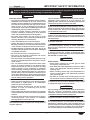
Safety information that appears in this manual is identified by
the following signal word panels:
WARNING
WARNING indicates a hazardous situation which, if not
avoided, could result in death or serious injury.
CAUTION
CAUTION indicates a hazardous situation which, if not
avoided, could result in minor or moderate injury.
NOTICE
NOTICE is used to address practices not related to
personal injury.
Record the model number, serial number, voltage, and
purchase date of the unit in the spaces below (specification
labels located on the Control Box, well enclosure, and
condensing unit, if equipped). Please have this information
available when calling Hatco for service assistance.
Model No. ________________________________________
Serial No. _________________________________________
Voltage ___________________________________________
Date of Purchase ___________________________________
Register your unit!
Completing online warranty registration will prevent delay in
obtaining warranty coverage. Access the Hatco website at
www.hatcocorp.com, select the Support pull-down menu,
and click on “Warranty”.
Business
Hours: 7:00 to 5:00 Monday–Friday,
Central Time (CT)
(Summer Hours — June to September:
7:00 to 5:00 Monday–Thursday
7:00 to 4:00 Friday)
Telephone: 800-558-0607; 414-671-6350
E-mail: [email protected]
24 Hour 7 Day Parts and Service
Assistance available in the United States
and Canada by calling 800-558-0607.
Additional information can be found by visiting our web site at
www.hatcocorp.com.

Form No. HCWBIRM-0121
3
English
IMPORTANT SAFETY INFORMATION
WARNING
ELECTRIC SHOCK HAZARD:
• Unit must be installed by qualified, trained installers.
Installation must conform to all local electrical and
plumbing codes. Installation by unqualified personnel
will void the unit warranty and may lead to electric
shock or burn, as well as damage to unit and/or its
surroundings. Check with local plumbing and electrical
inspectors for proper procedures and codes.
• Consult a licensed electrical contractor for proper
electrical installation conforming to local electrical
codes and the National Electrical Code (N.E.C.).
• Turn OFF power switch, turn off power at circuit
breaker, and allow unit to cool before performing any
cleaning, adjustments, or maintenance.
• Unit is not weatherproof. Locate unit indoors.
• Control box must be mounted in a vertical surface.
Mounting control box in a horizontal surface may result
in the collection of liquids and lead to electric shock.
• DO NOT submerge or saturate with water. Unit is not
waterproof. Do not operate if unit has been submerged
or saturated with water.
• Do not clean unit when it is energized or hot.
• This unit is not “jet-proof” construction. Do not use
jet-clean spray to clean this unit.
• This unit must be serviced by qualified personnel only.
Service by unqualified personnel may lead to electric
shock or burn.
• Use only Genuine Hatco Replacement Parts when
service is required. Failure to use Genuine Hatco
Replacement Parts will void all warranties and may
subject operators of the equipment to hazardous
electrical voltage, resulting in electrical shock or burn.
Genuine Hatco Replacement Parts are specified to
operate safely in the environments in which they are
used. Some aftermarket or generic replacement parts
do not have the characteristics that will allow them to
operate safely in Hatco equipment.
FIRE HAZARD:
• Installunitwithaminimumof3-1/2″(89mm)ofspace
from bottom of Hydro-Heater to all combustible
surfaces to prevent combustion.
• Install unit with a minimum of 2″ (51 mm) of space
between all sides of condensing unit and any
combustible surfaces.
• Installcondensingunitwithaminimumof6″(152mm)
of space between all sides of unit and any combustible
surfaces.
• Do not use harsh chemicals such as bleach (or cleaners
containing bleach), oven cleaners, or flammable
cleaning solutions to clean this unit.
EXPLOSION HAZARD: Do not store or use gasoline or
other flammable vapors or liquids in the vicinity of this or
any other appliance.
WARNING
This unit must be installed by qualified, trained installers.
Installation must conform to all local electrical and
plumbing codes. Check with local plumbing and electrical
inspectors for proper procedures and codes.
Make sure food product has been heated/chilled to the
proper food-safe temperature before placing in the unit.
Failure to heat/chill food product properly may result in
serious health risks. This unit is for holding pre-heated/
pre-chilled food product only.
Hatco Corporation is not responsible for actual food
product serving temperature. It is the responsibility of the
user to ensure that food product is held and served at a
safe temperature.
Make sure all operators have been instructed on the safe
and proper use of unit.
This unit is not intended for use by children or persons
with reduced physical, sensory, or mental capabilities.
Ensure proper supervision of children and keep them
away from unit.
This unit has no “user-serviceable” parts. If service
is required on this unit, contact an Authorized Hatco
Service Agent or contact the Hatco Service Department at
800-558-0607or414-671-6350.
CAUTION
BURN HAZARD:
• Some exterior surfaces on unit will get hot. Avoid
unnecessary contact with unit.
• Drainwatermayreachtemperaturesinexcessof200°F
(93°C). Use appropriate plumbing materials when
installing drain.
• Water in holding vessel may reach temperatures in
excess of 190ºF (88ºC). Use appropriate protection
when operating unit.
• Hot water in unit may cause scalding injury. Turn off
unit and allow unit to cool before draining or cleaning.
Locate unit at proper counter height in an area that is
convenient for use. The location should be strong enough
to support the weight of unit and contents.
NOTICE
Units are voltage and phase-specific. Refer to specification
label for electrical requirements before beginning
installation. Connecting unit to incorrect power supply will
void product warranty and may damage unit.
This unit is designed for use in environments where ambient
temperatureisbetween65°F(18°C)and86°F(30°C).
When shipped during cold weather months, store unit
for at least 10 hoursin an environment where ambient
temperature is between 65°F (18°C) and 86°F (30°C) to
prevent compressor and/or refrigerant line damage. If unit
is turned on and there is excessive noise and vibration,
turn off immediately and allow additional warmup time.
Read the following important safety information before using this equipment to avoid serious
injury or death and to avoid damage to equipment or property.

4
Form No. HCWBIRM-0121
English
IMPORTANT SAFETY INFORMATION
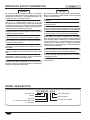
MODEL DESIGNATION
H C W B I R - x D A
Hot/Cold Well
Auto-Fill Equipped
Full-Size Pan Capacity
Drain Equipped
Insulated
Built-In
R = w/Remote Condensing Unit
X = Well Only
NOTICE
Do not locate unit in area with excessive air movement
around unit. Avoid areas that may be subject to active air
movements or currents (i.e., near exhaust fans/hoods, air
conditioning ducts, and exterior doors).
Provide louvered or grill-style openings with a minimum
size of 12″ x 12″/144 square inches (31 x 31 cm/
961 square cm) in the cabinetry in front of and behind the
condensing unit for proper ventilation. Failure to provide
adequate air flow through the condensing unit may cause
unit failure and will void the unit warranty.
Do not recirculate exhaust air inside cabinet when multiple
refrigerated wells are installed together. Intake air should
enter from outside of cabinet.
Transport and install unit in upright position only. Failure
to do so may result in damage to refrigeration system.
Use caution and avoid hitting condensing unit hoses/lines
when installing unit. Damage caused during installation is
not covered under warranty.
Auto-Fill units must be installed with adequate backflow
protection and must conform with all federal, state, and
local codes.
Do not use excessive force when tightening unions or
nuts. Over-tightening and excessive force may cause
leaks.
Do not locate unit in an area subject to excessive
temperatures or grease from grills, fryers, etc. Excessive
temperatures could cause damage to unit.
Damage to any countertop material caused by heat or cold
generated from Hatco equipment is not covered under
the Hatco warranty. Contact manufacturer of countertop
material for application information.
NOTICE
Do not obstruct access to Hydro-Heater cleanout drains.
Make sure installation location allows access to cleanout
drains for daily cleaning.
Do not use steel wool for cleaning. Steel wool will scratch
the finish.
Clean unit daily to avoid malfunctions and maintain
sanitary operation.
Use non-abrasive cleaners and cloths only. Abrasive
cleaners and cloths could scratch finish of unit, marring its
appearance and making it susceptible to soil accumulation.
Do not use harsh chemicals such as bleach, cleaners
containing bleach, or oven cleaners to clean this unit.
Incoming water in excess of 3 grains of hardness per
gallon (GPG) (0.75 grains of hardness per liter [GPL])
must be treated and softened before being supplied to
waterheater(s).Watercontainingover3GPG(0.75GPL)
will decrease efficiency, increase energy use, and reduce
operating life of unit through increased lime build-up.
Product failure caused by liming or sediment buildup is
not covered under warranty.
Use only delimers that are non-corrosive to aluminum,
brass, and stainless steel. Damage to unit caused by
corrosive materials is not covered under warranty.
Inspect unit regularly for lime and sediment buildup.
Excessive buildup may affect performance and reduce
operating life of unit.
This unit is intended for commercial use only—NOT for
household use.

Form No. HCWBIRM-0121
5
English
MODEL DESCRIPTION
All Models
Hatco Remote Drop-In Hot/Cold Wells are reliable and versatile.
Each unit has an insulated, stainless steel and aluminized steel
housing. For hot operation, an FR2 series Hydro-Heater is
mounted under the well and is designed to heat or hold foods
at safe temperatures between 140ºF and 190ºF (60°C and
88ºC). The Hydro-Heater features a tubular water chamber
with a spiral heating element wrapped around the outside.
They include a stainless steel front, powdercoated body, a
Thread (GHT) drain connection. For cold operation, the sides
of the internal well are completely surrounded with a copper
evaporator coil to provide even chilling from top to bottom.
Remote Drop-In Hot/Cold Wells are designed, manufactured,
and tested to maintain safe food holding temperatures.
Controls for the Remote Drop-In Hot/Cold Wells are housed in a
single, remote control box. They include a three position Power
I/O/I (on/off/on) Switch, two digital temperature controllers,
and a drain status indicator light. The control box is connected
assembly. Drop-In Hot/Cold Wells are hardwired directly to a
power source for a secure and cord-free serving area.
All Remote Drop-In Hot/Cold Well models are designed to be
mounted to the topside of various types of countertop material
including stainless steel, wood, Corian, and Swanstone.
Depending on the model’s pan capacity, each Remote Drop-In
Hot/Cold Well is supplied from the factory with the proper size
Water Baffle and appropriate number/configuration of Pan
(508 mm) Pan Support Bars for cold operation. Each individual
well is capable of holding a variety of pan combinations of full
size, 1/2-size, 1/3-size, and/or 1/6-size pans with additional
accessory Pan Support Bars.
Food Pans, Pan Support Bars, and a flush hose kit are available
as accessories for the Remote Drop-In Hot/Cold Wells. Refer
to the OPTIONS AND ACCESSORIES section in this manual
for details.
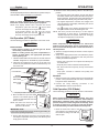
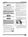
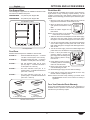
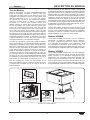
HCWBIR Models
HCWBIR models consist of a hot/cold well, a remote-mounted
control box, a remote-mounted condensing unit, and a thermal
expansion valve (TXV valve, shipped loose). All plumbing and
electrical connections between the components as well as to
the electrical supply are the responsibility of the end user and
a qualified installer.
HCWBIX Models
HCWBIX models consist of a hot/cold well with a solenoid
valve, a remote-mounted control box, and a thermal expansion
valve (TXV valve, shipped loose). These components must
be connected to an end user-supplied condensing unit. All
plumbing and electrical connections between the components
as well as to the electrical supply are the responsibility of the
end user and a qualified installer.
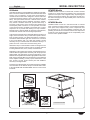
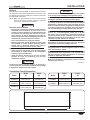
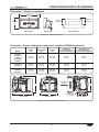
Condensing Unit
(HCWBIR Models only)
Control Box
(All Models)
TXV Valve
(All Models)
Pans Not Included
HCWBIR-2 Model Shown

6
Form No. HCWBIRM-0121
English
Minimum Maximum
Water Pressure 20 psi (138 kPa) 120 psi (827 kPa)
Water Temperature 35°F (2°C) 160°F (71°C)
Model
Width
(A)
Depth
(B)
Overall
Height (C)
Well
Height (D)
HCWBIR-5
71
(1803 mm)
27
(686 mm)
26-5/8
(674 mm)
12
(305 mm)
HCWBIR-6
84
(2134 mm)
27
(686 mm)
26-5/8
(674 mm)
12
(305 mm)
Model
Width
(A)
Depth
(B)
Overall
Height (C)
Well
Height (D)
HCWBIR-2
32
(813 mm)
27
(686 mm)
26-5/8
(674 mm)
12
(305 mm)
HCWBIR-3
45
(1143 mm)
27
(686 mm)
26-5/8
(674 mm)
12
(305 mm)
HCWBIR-4
58
(1473 mm)
27
(686 mm)
26-5/8
(674 mm)
12
(305 mm)
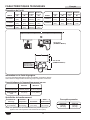
SPECIFICATIONS
Water Supply Specifications
Refrigerant Specifications
Hatco Remote Drop-In Hot/Cold Wells use R-513A refrigerant
in the condensing unit.
D
C
A
Front View
(Model HCWBIR-6)
Side View
(Model HCWBIR-6)
B
Specification Label
on side of control
enclosure.
Unit Dimensions
Discharge
Pressure
Suction
Pressure Superheat Subcooling
115 to 125 psig
(7.9 to 8.6 bar)
6 to 9 psig
(0.4 to 0.6 bar)
4° to 10°F
(2.2° to 5.6°C)
5° to 10°F
(2.8° to 5.6°C)
Operating Specifications
NOTE: The Operating Specifications are accurate for units in an ambient
air temperature of 75°F (24°C).
High Side Low Side
186 psig
(12.8 bar)
88 psig
(6.07 bar)
Design Pressure

Form No. HCWBIRM-0121
7
English
Model
Width
(A)
Depth
(B)
Height
(C)
Mounting Hole
Width (D)
Mounting Hole
Depth (E)
HCWBIR-1
HCWBIR-S1
HCWBIR-2
HCWBIR-S2
HCWBIR-3
14-5/8
(371 mm)
12-1/4
(312 mm)
11-3/8
(289 mm)
6-1/2
(165 mm)
9-1/2
(242 mm)
HCWBIR-S3
HCWBIR-4
14-1/2
(369 mm)
12-1/4
(312 mm)
11-3/8
(289 mm)
6-1/2
(165 mm)
9-1/2
(242 mm)
HCWBIR-S4
HCWBIR-5
HCWBIR-6
17-1/2
(444 mm)
16-3/8
(415 mm)
12-1/8
(306 mm)
9-1/4
(235 mm)
11-1/4
(286 mm)
Dimensions — Condensing Unit (HCWBIR Models only)
Top ViewFront View Side View
C
A
B
3X Ø 0.375
(10 mm)
D
E
Air Flow
Dimensions — Control Box
15-1/8″
(384 mm)
Front View Top ViewSide View
8″
(203 mm)
5-9/16″
(140 mm)
4-3/8″
(109 mm)
Dimensions — Control Box
SPECIFICATIONS
Dimensions — Condensing Unit

8
Form No. HCWBIRM-0121
English
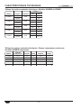
Model
Compressor
Size Voltage Hertz Watts Amps
HCWBIR-2 1/5 hp 120 60 300 3.8
HCWBIR-3 1/5 hp 120 60 300 3.8
HCWBIR-4 1/3 hp 120 60 450 5.9
HCWBIR-5 5/8 hp 120 60 800 8.7
HCWBIR-6 5/8 hp 120 60 800 8.7
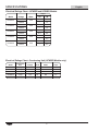
SPECIFICATIONS
Electrical Ratings Chart—Condensing Unit (HCWBIR Models only)
Electrical Ratings Chart—HCWBIR and HCWBIX Models
Model Voltage Watts
Amps
1 Ø 3 Ø
HCWBIX-2
120/208
3000
14.5 8.4
120/240 --- 7.3
HCWBIX-3
120/208
3000
14.5 8.4
120/240 ---- 7.3
HCWBIX-4
120/208
4000
19.2 11.2
120/240 16.7 9.6
HCWBIX-5
120/208
6000
28.8 16.7
120/240 --- 14.5
HCWBIX-6
120/208
6000
28.8 16.7
120/240 --- 14.5

Form No. HCWBIRM-0121
9
English
INSTALLATION
General
Remote Drop-In Hot/Cold Wells are shipped from the factory
as components that require installation and connection. Use
the following procedures to install each component and make
the appropriate connections.
NOTE: Make sure the installation location provides enough
room for the remote mounted control box, electrical
connections, and plumbing connections.
WARNING
ELECTRIC SHOCK HAZARD:
• Unit must be installed by qualified, trained installers.
Installation must conform to all local electrical and
plumbing codes. Installation by unqualified personnel
will void the unit warranty and may lead to electric
shock or burn, as well as damage to unit and/or its
surroundings. Check with local plumbing and electrical
inspectors for proper procedures and codes.
• Unit is not weatherproof. Locate unit indoors.
• Remote control box must be mounted on vertical wall
and installed in vertical position. Mounting remote
control box in horizontal position may result in
collection of liquids and lead to electric shock.
FIRE HAZARD:
• Installunitwithaminimumof3-1/2″(89mm)ofspace
from bottom of Hydro-Heater to all combustible
surfaces to prevent combustion.
• Install unit with a minimum of 2″ (51 mm) of space
between all sides of condensing unit and any
combustible surfaces.
CAUTION
Locate unit at proper counter height in an area that is
convenient for use. The location should be strong enough
to support the weight of unit and contents.
NOTICE
Transport and install unit in upright position only. Failure
to do so may result in damage to refrigeration system.
This unit is designed for use in environments where ambient
temperatureisbetween65°F(18°C)and86°F(30°C).
When shipped during cold weather months, store unit
for at least 10 hours in an environment where ambient
temperature is between 65°F (18°C) and 86°F (30°C) to
prevent compressor and/or refrigerant line damage. If unit
is turned on and there is excessive noise and vibration,
turn off immediately and allow additional warmup time.
Provide louvered or grill-style openings with a minimum
size of 12″ x 12″/144 square inches (31 x 31 cm/
961 square cm) in the cabinetry in front of and behind the
condensing unit for proper ventilation. Failure to provide
adequate air flow through the condensing unit may cause
unit failure and will void the unit warranty.
Do not locate unit in an area subject to excessive
temperatures or grease from grills, fryers, etc. Excessive
temperatures could cause damage to the unit.
Do not recirculate exhaust air inside cabinet when multiple
refrigerated wells are installed together. Intake air should
enter from outside of cabinet.
Damage to any countertop material caused by heat or cold
generated from Hatco equipment is not covered under
the Hatco warranty. Contact manufacturer of countertop
material for application information.
Do not obstruct access to Hydro-Heater cleanout drains.
Make sure installation location allows access to cleanout
drains for daily cleaning.
continued...
Model
Width
(A)
Depth
(B)
HCWBIR-2
30-1/831
(765787 mm)
25-3/1626
(640660 mm)
HCWBIR-3
43-1/844
(10951118 mm)
25-3/1626
(640660 mm)
HCWBIR-4
56-1/857
(14261448 mm)
25-3/1626
(640660 mm)
Model
Width
(A)
Depth
(B)
HCWBIR-5
69-1/870
(17561778 mm)
25-3/1626
(640660 mm)
HCWBIR-6
82-1/883
(20862108 mm)
25-3/1626
(640660 mm)
B
A
Countertop Cutout Dimensions

10
Form No. HCWBIRM-0121
English
INSTALLATION
All Remote Drop-In Hot/Cold Wells are shipped in a shipping
frame for protection and stability. Keep the unit in the shipping
frame until the unit and the installation site are completely
prepared for the unit to be installed.
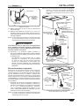
1. Remove all external packaging from the unit.
2. Remove tape, protective packaging, and literature from all
surfaces of unit.
NOTE: To prevent delay in obtaining warranty coverage, complete
online warranty registration. See the IMPORTANT
OWNER INFORMATION section for details.
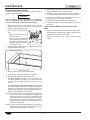
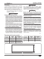
3. Cut the appropriate opening in the countertop for the unit
being installed. Refer to “Countertop Cutout Dimensions”
in this section.
4. If installing the control box remotely, cut and drill the
appropriate holes in the vertical surface where the control
box will be installed. Refer to the “Installing the Remote
Control Box” procedure for cutout dimensions.
• The cutout depth required for the control box is
5. Make structural modifications or add bracing underneath
the countertop to ensure the countertop will support the
weight of the unit and its contents.
6. Make sure the following interior clearances are available:
condensing unit and any combustible surface.
bottom of the Hydro-Heater and any combustible
surface.
NOTE: The countertop must be level to ensure proper draining
of the hot/cold well.
NOTICE
Use caution and avoid hitting condensing unit hoses/lines
when installing unit. Damage caused during installation is
not covered under warranty.
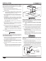
7. Lift the unit out of the wooden shipping frame and carefully
lower it into the countertop cutout. This step requires two
or more people, depending on the unit.
8. Apply National Sanitation Foundation-approved (NSF-
approved) silicone sealant around the edge of the unit to
seal it to the countertop.
9. Install the control box in the desired location, if installing
remotely.
(1829 mm) of the Hydro-Heater. Refer to the “Installing
the Remote Control Box” procedure in this section.
Countertop
Coutout
Hot/Cold Well
Well
Hydro-Heater
Installing a HCWBIR-3 Model
CAUTION
BURN HAZARD: Drain water may reach temperatures
in excess of 200°F (93°C). Use appropriate plumbing
materials when installing drain.
NOTE: Consult a licensed plumber for proper drain and water
supply installation that conforms to local plumbing
codes.
Thread (GHT) drain fitting on the front of the Hydro-Heater.
NOTE: Approved air gap or other back-flow prevention device
must be installed by a licensed plumber, if required.
11. For HCWBIR Models, install the condensing unit in the
desired location. Refer to the SPECIFICATION section for
installation dimensions.
• Make sure the installation site offers continuous air flow
ventilation to the condensing unit.
between all sides of the condensing unit and any
combustible surface.
NOTICE
Auto-Fill units must be installed with adequate backflow
protection and must conform with all federal, state, and
local codes.
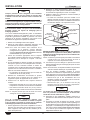
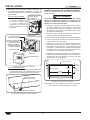
12. Have qualified installers perform the “Connecting the
Components” procedure in this section.
fitting for the Auto-Fill system on the bottom right side of
the Hydro-Heater. Refer to “Water Supply Specifications”
in the SPECIFICATIONS section of this manual for water
supply requirements.
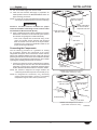
Electrical
connection
to control
enclosure.
3/4" GHT
Drain Fitting
Hydro-Heater
3/4" GHT
Inlet Fitting
Connecting the Plumbing Fittings

Form No. HCWBIRM-0121
11
English
14. Turn on the water supply and check for leaks.
15. Clean the well enclosure thoroughly in preparation for
initial operation. Refer to the MAINTENANCE section for
proper cleaning procedures.
NOTE: If a catch pan is used underneath the drain fitting, make
sure the pan is emptied regularly to prevent over-flowing.
WARNING
Consult a licensed electrical contractor for proper
electrical installation conforming to local electrical codes
and the National Electrical Code (N.E.C.).
16. Have a qualified electrician install a hardwired connection
between the unit and the on-site electrical system (refer to
the included wiring diagram for additional details).
(1524 mm) flexible conduit assembly with electrical
leads is located on the left side of the Hydro-Heater,
toward the rear. Check the specification label for the
proper electrical specifications.
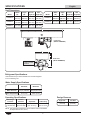
Connecting the Components
Use the following procedure as a guideline for making
the connections between the components of the remote
refrigerated well system. These connections must be made by
trained and qualified installers and must comply with all local
plumbing and electrical codes. Refer to the SPECIFICATIONS
section and the wiring diagram included with the unit for details
regarding the plumbing and electrical connections.
1. Connect the liquid and suction refrigerant lines between
the condensing unit, the TXV valve, and the hot/cold well
evaporator coil. Refer to the appropriate illustration below
and the SPECIFICATIONS section for connection details.
NOTE: The maximum refrigerant line length between the
condensing unit and the evaporator coil is 50 feet (15 m).
NOTE: For refrigerant line connections, use a self-fluxing
brazing compound (example = Sil-Fos 5
®
) at a brazing
temperature range of 1300–1500°F (704–816°C).
Liquid
Connection
(1/4″ O.D. tube)
Liquid Connection
(3/8″ O.D. tube)
Condensing
Unit
Well
TXV Valve
Suction Connection
(3/8″ O.D. tube)
TXV Bulb
Fasten TXV bulb to
the suction side of
evaporator coil here.
Suction Connection
(3/8″ O.D. tube)
Suction Connection
(3/8″ O.D. tube)
HCWBIR Model Refrigerant Connections
(Hydro-Heater removed for clarity)
Liquid Connection
(3/8″ O.D. tube)
Well
TXV Valve
Suction Connection
(3/8″ O.D. tube)
Suction Connection
(3/8″ O.D. tube)
Solenoid Valve
From
Condensing
Unit
To Condensing
Unit
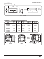
HCWBIX Model Refrigerant Connections
(Hydro-Heater removed for clarity)
continued...
INSTALLATION

12
Form No. HCWBIRM-0121
English
INSTALLATION
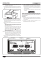
2. Have a qualified electrician make the appropriate electrical
connections to the Control Box. Refer to the wiring diagram
for details.
For HCWBIR Models:
Condensing Unit
Power Input
a. Connect power from the
POWER OUT terminal block,
through the power output
knockout, to the power input
on the condensing unit.
Power Input
Power Output
(to condensing unit on
HCWBIR Models or
solenoid valve on
HCWBIX Models)
Temperature Probe
Wire Inlet
Terminal Blocks
Digital Temperature
Controller
Access Cover
Control Box Connections
For HCWBIX Models:
a. Connect power from the POWER OUT terminal block,
through the power output knockout, to the solenoid valve
on the hot/cold well.
Solenoid Valve
Power Input
Temperature probe installed here.
HCWBIX Model Electrical Connections
Installing the Remote Control Box
Use the following procedure to install the remote control box.
WARNING
Control box must be mounted in a vertical surface.
Mounting control box in a horizontal surface may result in
the collection of liquids and lead to electric shock.
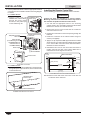
1. Cut and drill the appropriate holes in the mounting
surface. Refer to the “Control Box Cutout and Screw Hole
Dimensions” chart for the cutout dimensions.
2. Remove the four trim cover screws from the control box
and remove the trim cover.
3. Position the control box into the cutout opening through the
backside.
4. Fasten the control box to the vertical surface using four
screws (not supplied).
where the trim cover will contact the cabinet surface. Refer
to the “Control Box Cutout and Screw Hole Dimensions”
illustration for more information.
6. Reinstall the trim cover on the control box and secure in
position using the four trim cover screws. Make sure to
embed the trim cover edge into the silicone.
7/16″
(11 mm)
3/8″ (10 mm)
Silicone Sealant
5-5/8″
(143 mm)
13-1/16″
(332 mm)
13-7/16″
(341 mm)
3-1/2″
(89 mm)
1-1/16″
(27 mm)
Control Box Cutout and Screw Hole Dimensions
NOTE: Make sure the width of the control box cutout does not
exceed the above dimension.

Form No. HCWBIRM-0121
13
English
General
Use the appropriate procedure in this section to operate a Drop-In
Hot/Cold Well in either HOT Mode or COLD Mode.
WARNING
Read all safety messages in the Important Safety
Information section before operating this equipment.
NOTE: If the display flashes “OFF” and then the current
temperature, press and hold the key for three
seconds. The display will no longer flash “OFF”.
If the display flashes “df” and then the current
temperature, press and hold the key for three
seconds. The display will no longer flash “df”.
Hot Operation (HOT Mode)
Use the following procedure to operate the unit in HOT mode.
CAUTION
BURN HAZARD:
• Some exterior surfaces on unit will get hot. Avoid
unnecessary contact with unit.
• Water in holding vessel may reach temperatures in
excess of 190ºF (88ºC). Use appropriate protection
when operating unit.
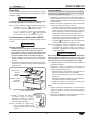
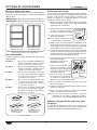
1. Install the water baffle into the bottom of the well. Note the
“PROBE” designation on the baffle for proper installation.
2. Install the pan platform(s) into the top of the well. The
number of pan platforms included is determined by the
size of the well.
Water Baffle
Water Level
Probe
Pan Platforms
“PROBE”
Designation
Preparing the Well for HOT Mode (HCWBIX-3 shown)
Drain Lever
in closed
position.
3. Move the drain lever up to the closed
position. The indicator light on the
control box will illuminate when the
drain is closed.
NOTE: The drain lever must be in the
closed position for the unit to
operate in HOT Mode.
IMPORTANT NOTE
Empty pans should be placed in the well during pre-heating for
unit to reach operating temperature.
4. Fill the well with empty food pans. The well will heat to
the setpoint temperature more quickly and efficiently with
empty pans in the well.
5. Move the Power I/O/I (on/off/on) switch to the HOT I (on)
position.
• The Auto-Fill system will activate, and the well will fill
with water until the water reaches the water level probe.
During operation, the Auto-Fill system will maintain the
water level automatically using the water level probe.
• The digital temperature controller will energize and
“ON” will appear on the display, followed by the current
temperature of the unit.
• The symbol on the display will illuminate to show
the Hydro-Heater is active and heating the well.
NOTE: The unit is pre-set at the factory to a HOT setpoint
temperature of 192°F (89°C). If adjustment to the
setpoint temperature is required, refer to the “Changing
the Setpoint Temperature” in this section.
WARNING
Hatco Corporation is not responsible for actual food
product serving temperature. It is the responsibility of the
user to ensure that food product is held and served at a
safe temperature.
6. Allow the unit approximately 60 minutes to reach setpoint
temperature.
7. Verify on the display that the unit has reached the proper
setpoint temperature, and load the well with pans that
contain pre-heated food product.
• Always use a food pan. Do not place food directly into
the heated well.
• Keep all pans in well to maintain well temperature.
• Stir thick food items frequently to keep food heated
uniformly.
• Keep pans covered to maintain food quality and
temperature.
Shutdown
1. Move the Power I/O/I (on/off/on) switch to the center O (off)
position. The Hydro-Heater will shut down, and the Auto-
Fill system will be deactivated.
2. Perform the “Daily Cleaning” procedure in the
MAINTENANCE section of this manual.
Cold Operation (COLD Mode)
Use the following procedure to operate the unit in COLD Mode.
NOTICE
When shipped during cold weather months, store unit
for at least 10 hours in an environment where ambient
temperature is between 65°F (18°C) and 86°F (30°C) to
prevent compressor and/or refrigerant line damage. If unit
is turned on and there is excessive noise and vibration,
turn off immediately and allow additional warmup time.
Drain Lever
in open
position.
Drain Lever
in open
position.
1. Move the drain lever down to the
open position. The indicator light on
the control box will go out when the
drain is open.
continued...
OPERATION

14
Form No. HCWBIRM-0121
English
OPERATION
NOTE: The drain lever must be in the open position for the unit
to operate in COLD Mode.
2. Install the pan support bars(s) into the well. The number of
pan support bars included is determined by the size of the
well.
Pan Support
Bar
Preparing the Well for COLD Mode (HCWBIX-3 shown)
3. Fill the well with empty food pans. The well will chill to
the setpoint temperature more quickly and efficiently with
empty pans in the well.
4. Move the Power I/O/I (on/off/on) switch to the COLD I (on)
position.
• The digital temperature controller will energize and
“ON” will appear on the display, followed by the current
temperature of the unit.
• A five minute programmed delay begins before the
condensing unit starts up. The delay is in place as a
safeguard when switching from HOT to COLD Mode.
• After the five minute delay, the symbol on the
display will illuminate to show the condensing unit is
active and chilling the well.
NOTE: The unit is pre-set at the factory to a COLD setpoint
temperature of 32°F (0°C). If ambient conditions require
adjustment to the setpoint temperature, refer to the
“Changing the Setpoint Temperature” in this section.
5. Allow the unit approximately 60 minutes to reach setpoint
temperature.
6. Verify on the display that the unit has reached the proper
setpoint temperature, and replace the empty pans in the
well with pans that are loaded with pre-chilled food product.
• Always use a food pan. Do not place food directly into
the hot/cold well.
• Stir thick food items frequently to keep food chilled
uniformly.
WARNING
Hatco Corporation is not responsible for actual food
product serving temperature. It is the responsibility of the
user to ensure that food product is held and served at a
safe temperature.
Shutdown
1. Move the Power I/O/I (on/off/on) Switch to the center O (off)
position. The digital temperature controller and condensing
unit will shut off.
2. Perform the “Daily Cleaning” procedure in the
MAINTENANCE section of this manual.
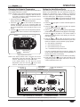
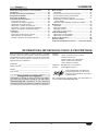
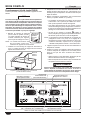
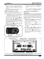
COLD Digital
Temperature Controller
HOT Digital
Temperature Controller
Drain Position Indicator
(Off = Open/Cold, On = Closed/Hot)
Power I/O/I
(on/off/on)
Unit “Active”
Symbol
HCWBI Series Control Box (shown operating in HOT Mode)

Form No. HCWBIRM-0121
15
English
OPERATION
Changing the Setpoint Temperature
Use the following procedure to change the setpoint temperature
on the digital temperature controller.
NOTE: Changes to the setpoint temperature should be made
in small increments (1 to 2 degrees). Wait at least two
hours after a change in setpoint temperature before
checking for the desired result.
1. Press and hold the key for one second until the
display flashes the current setpoint temperature.
2. Press the or key to increase or decrease the
setpoint temperature. If no key is pressed within 60
seconds, the display will revert to normal operation and
the current temperature of the unit will be shown on the
display.
3. Press the key to lock in the new setpoint temperature.
The display will revert to show the current temperature of
the unit.
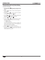
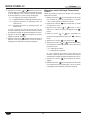
Display
Down Arrow/
Defrost Key
Unit
“Active”
Symbol
Up Arrow/
Standby Key
SET
Key
Digital Temperature Controller
NOTE: If the display flashes “OFF” and then the current
temperature, press and hold the key for three
seconds. The display will no longer flash “OFF”.
If the display flashes “df” and then the current
temperature, press and hold the key for three
seconds. The display will no longer flash “df”.
Setting the Auto-Defrost Cycle
Hot/cold wells are programmed at the factory with the auto-
defrost cycle deactivated. Use the following procedure to
activate the auto-defrost cycle if ambient or operational
conditions require the unit to defrost occasionally. When the
unit is in a defrost cycle, will appear on the display.
1. Press and hold the key for three seconds to access
programming mode. “PS” (password) will appear on the
display.
2. Press the key again. A numeric value will appear on
the display.
3. Press the or key until the number “22” appears
on the display, then press the key.
4. Use the or key to scroll through the programmable
parameters until “dI” (defrost interval) appears on the display.
5. Press the key to select “dI”. The current number of
defrost cycles will be shown on the display. For new units,
this value will be “0”.
6. Press the or key within 60 seconds to scroll to
the desired number of hours between defrost cycles. See
below for examples of how the defrost cycle(s) operate:
“0” = auto-defrost is deactivated
“1” = unit will defrost every hour
“4” = unit will defrost every four hours
“12” = unit will defrost every twelve hours
If no key is pressed within 60 seconds, the display will
revert to normal operation and the current temperature of
the unit will be shown on the display.
7. Press the key to lock in the new defrost cycle setting.
8. Press and hold the key for three seconds to exit
programming mode. The display will revert to show the
current temperature of the unit.
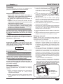
COLD Digital
Temperature
Controller
HOT Digital
Temperature Controller
Drain Position Indicator
(Off = Open/Cold, On = Closed/Hot)
Power I/O/I (On/Off/On)
Switch
Unit “Active”
Symbol
HCWBI Series Control Box (shown operating in COLD Mode)

16
Form No. HCWBIRM-0121
English
OPERATION
Changing Fahrenheit and Celsius Setting
Use the following procedure to change between Fahrenheit
and Celsius on the display.
1. Press and hold the key for three seconds to access
programming mode. “PS” (password) will appear on the
display.
2. Press the key again. A numeric value will appear on
the display.
3. Press the or key until the number “22” appears
on the display, then press the key.
4. Use the or key to scroll through the programmable
parameters until appears on the display.
5. Press the key to select .
6. Press the or key within 60 seconds to scroll to
the desired setting. See below for the correct setting:
“0” = Displays Celsius
“1” = Displays Fahrenheit
If no key is pressed within 60 seconds, the display will
revert to normal operation and the current temperature of
the unit will be shown on the display.
7. Press the key to lock in the new setting.
8. Press and hold the key for three seconds to exit
programming mode. The display will revert to show the
current temperature of the unit.

Form No. HCWBIRM-0121
17
English
MAINTENANCE
General
Drop-In Hot/Cold Wells are designed for maximum durability
and performance, with minimum maintenance.
WARNING
ELECTRIC SHOCK HAZARD:
• Turn OFF power switch, turn off power at circuit
breaker, and allow unit to cool before performing any
cleaning, adjustments, or maintenance.
• Do not clean unit when it is energized or hot.
• This unit is not “jet-proof” construction. Do not use
jet-clean spray to clean this unit.
• This unit must be serviced by qualified personnel only.
Service by unqualified personnel may lead to electric
shock or burn.
FIRE HAZARD: Do not use harsh chemicals such as
bleach (or cleaners containing bleach), oven cleaners, or
flammable cleaning solutions to clean this unit.
This unit has no “user-serviceable” parts. If service
is required on this unit, contact an Authorized Hatco
Service Agent or contact the Hatco Service Department at
800-558-0607or414-671-6350.
CAUTION
BURN HAZARD: Hot water in unit may cause scalding
injury. Turn off unit and allow unit to cool before draining
or cleaning.
NOTICE
Do not use steel wool for cleaning. Steel wool will scratch
the finish.
Clean unit daily to avoid malfunctions and maintain
sanitary operation.
Use non-abrasive cleaners and cloths only. Abrasive
cleaners and cloths could scratch finish of unit, marring its
appearance and making it susceptible to soil accumulation.
Do not use harsh chemicals such as bleach, cleaners
containing bleach, or oven cleaners to clean this unit.
Daily Cleaning
To preserve the finish and maintain operation of the unit,
perform the following cleaning procedure daily.
1. Move the Power I/O/I (on/off/on) Switch to the center O
(off) position and allow the unit to cool/defrost.
2. Remove and wash all pans, supports, and adapters as
well as the water baffle, if installed.
Drain Lever
in open
position.
Drain Lever
in open
position.
3. If cleaning after operating in HOT
Mode, move the drain lever to the
open position to remove water from
the well.
4. If cleaning after operating in HOT
Mode, perform the “Cleaning the
Hydro-Heater” procedure in this
section.
5. Clean the well using a clean cloth or sponge and mild
detergent. Use a plastic scouring pad to remove any
hardened food particles or mineral deposits.
6. Rinse the well(s) thoroughly with hot water to remove all
detergent residue.
7. Wipe down well with a clean, sanitized cloth to remove
the detergent residue. Repeat until all detergent residue is
gone and the well is clean.
8. Wipe dry the entire unit using a non-abrasive, dry cloth.
9. Wipe down the outside of the louvered or grill-style panels
installed in the cabinet ventilation openings.
Monthly Cleaning
Perform the following procedure monthly to maintain proper
and efficient operation as well as prevent malfunction when
operating in COLD Mode.
1. Remove and clean both sides of the louvered or grill-style
panels that are installed in the ventilation openings. Dirt
and dust build-up in the panels can restrict air flow to the
condensing unit and cause over-heating.
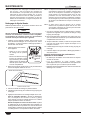
2. Clean the condenser coil cooling fins. Dirt, dust, and lint
build-up in the cooling fins will prevent proper cooling of
the refrigerant in the refrigeration system. This buildup will
cause inefficient operation and can lead to unit failure. Use
the following methods to clean the condenser coil cooling
fins:
• Vacuum the cooling fins.
• Brush the cooling fins vertically using a condenser
coil brush. NOTICE: Use caution when brushing
the cooling fins, they are delicate and can be bent
easily. DO NOT use a wire brush.
Condenser Coil
Cooling Fins
Condenser Coil Cooling Fins
NOTE: Depending on the conditions of the installation site, this
cleaning procedure may need to be performed more
often or less often than monthly. Monitor the level of dirt,
dust, and lint buildup on the panels and cooling fins,
and make adjustments to the frequency of cleanings as
necessary.

18
Form No. HCWBIRM-0121
English
MAINTENANCE
Cleaning the Hydro-Heater
Perform the following procedure daily to ensure consistent
operation of the Hydro-Heater.
NOTICE
Use only delimers that are non-corrosive to aluminum,
brass, and stainless steel. Damage to unit caused by
corrosive materials is not covered under warranty.
1. Make sure the unit is off, cool, and the water in the well
Cleaning” procedure in this section.
Pipe Cap
Cleanout
Drain
2. Drain all water remaining in the
unit.
• Make sure the drain lever is in
the open position.
• Place a catch pan below the
cleanout drain(s), remove the
pipe cap(s) from the drain(s)
and allow remaining water to
empty from the unit.
3. Clean the water level probe on the sidewall and wipe any
visible deposits from the well.
Water Level Probe
Water Level Probe
4. Move the drain lever up to the closed position.
5. Install the pipe cap(s) onto the clean-out drain(s).
6. Manually add appropriate solution to the unit.
For daily cleaning: Dissolve a safe, non-toxic, non-
corrosive sanitizer into 1 gallon (3.7 L) of hot water and
pour into the well. Allow to soak for a minimum of 15
minutes.
For removing lime and mineral deposits: Add water
and white vinegar mixture to the unit. The mixture should
consist of 75% water and 25% white vinegar. Do not use
flavored vinegar. Allow the unit to stand with the mixture in
the well for an appropriate period of time.
NOTE: The amount of lime and mineral content in the water
and how often the unit is operated in HOT Mode will
dictate how often the unit needs to be delimed. Units
used with water that contains high lime and mineral
content may require deliming on a daily basis. Product
failure caused by liming or sediment buildup is not
covered under warranty.
NOTE: The time required will vary depending on the solution
used and amount of deposits in the well. Heavy scale
buildup may require additional treatments.
7. After cleaning, drain all expended solution from the unit
through the drain and the clean-out drain(s).
8. Thoroughly rinse unit with fresh water until discharge is
clear and all sanitizers have been removed and rinsed.
9. Upon visual inspection, if the Hydro-Heater tank is not
10. Install the pipe cap(s) onto the clean-out drain(s).
11. Continue with step 5 of the “Daily Cleaning” procedure in
this section.
Helpful Hints for Maximum Performance in HOT
Mode
• Keep Hydro-Heater inlet and outlet strainers free of debris.
• Always keep the perforated water baffle in place and free
of debris when operating in HOT Mode.
• Delime unit regularly using a non-corrosive deliming
solution.

Form No. HCWBIRM-0121
19
English
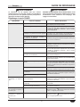
Symptom Probable Cause Corrective Action
Well too cold. Unit not allowed to preheat. Hydro-heaters require a minimum of 60 minutes to preheat.
Setpoint temperature set too low. Adjust the HOT controller setpoint temperature to a higher
setting. Refer to the “Changing the Setpoint Temperature”
procedure in the OPERATION section.
Unit not filled with food pans/one or more open
pan positions.
Fill the well with food pans. The well will heat to the setpoint
temperature more quickly and hold more efficiently when
filled with pans.
Digital temperature controller not working
properly.
Contact Authorized Service Agent or Hatco for assistance.
Heating element(s) not working.
Voltage supplied is incorrect. Verify correct voltage is supplied to unit. Unit will not operate
properly with low supply voltage.
Wells too hot. Setpoint temperature set too high. Adjust the HOT controller setpoint temperature to a lower
setting. Refer to the “Changing the Setpoint Temperature”
procedure in the OPERATION section.
Digital temperature controller not working
properly.
Contact Authorized Service Agent or Hatco for assistance.
Voltage supplied is incorrect. Verify correct voltage is supplied to unit. High supply voltage
will cause unit to overheat and my damage unit.
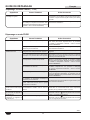
Controller display flashes
“OFF” and unit is not working.
The unit is in Standby mode.
Press and hold the key for three seconds. The display
will no longer flash “OFF”.
Controller display flashes “df”
and unit is not working.
The unit is in Defrost mode.
Press and hold the key for three seconds. The display
will no longer flash “df”.
No heat. Drain lever is not in the closed position. Move drain lever up to closed position and make sure
Power I/O/I (on/off/on) switch is in HOT “I” (on) position.
Lever must be in the closed position for unit to operate in
HOT Mode.
Circuit breaker tripped. Reset circuit breaker. If circuit breaker continues to trip,
contact Authorized Service Agent or Hatco.
Temperature Control not working properly.
Contact Authorized Service Agent or Hatco for assistance.
Heating element(s) not working.
Auto-Fill system not working. Water level probe is dirty and not “sensing”
properly.
Perform the “Daily Cleaning” procedure in the Maintenance
section with special focus on the water level probe.
Water not supplied to fill valve. Verify water supply is correctly installed and running.
Water fill valve malfunctioning. Contact Authorized Service Agent or Hatco for assistance.
Heating element(s) burn out. The well is dry or has a low level of water. Verify water supply is correctly installed and running. If
problem is not with water supply, contact Authorized Service
Agent or Hatco for assistance.
Deposits built up in the heater pipes are
restricting water flow. (Perform the entire
“Daily Cleaning” procedure in MAINTENANCE
section.)
Contact Authorized Service Agent or Hatco for assistance.
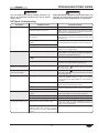
TROUBLESHOOTING GUIDE
WARNING
This unit must be serviced by qualified personnel only.
Service by unqualified personnel may lead to electric
shock or burn.
WARNING
ELECTRIC SHOCK HAZARD: Turn OFF power switch, turn
off power at circuit breaker, and allow unit to cool before
performing any cleaning, adjustments, or maintenance.
HOT Mode Troubleshooting

20
Form No. HCWBIRM-0121
English
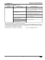
Symptom Probable Cause Corrective Action
Well too cold. Setpoint temperature set too low. Adjust the COLD controller setpoint temperature to a higher
setting. Refer to the “Changing the Setpoint Temperature”
procedure in the OPERATION section.
Digital temperature controller not working
properly.
Contact Authorized Service Agent or Hatco for assistance.
Well not cold enough. Food product not pre-chilled before loading in
well.
Load well with pre-chilled food product only.
Unit not filled with food pans/one or more open
pan positions.
Fill the well with food pans. The well will chill to the setpoint
temperature more quickly and hold more efficiently when
filled with pans.
Setpoint temperature set too high. Adjust the COLD controller setpoint temperature to a lower
setting. Refer to the “Changing the Setpoint Temperature”
procedure in the OPERATION section.
Condenser coil and/or ventilation panels are
plugged with dirt/dust.
Clean the condenser coil and ventilation panels. Refer
to the “Cleaning the Condensing Unit” procedure in the
MAINTENANCE section.
Too much frost built up inside of well. Turn off, defrost, and clean the unit. Activate an auto-defrost
cycle, if necessary (refer to the “Setting the Auto-Defrost
Cycle” procedure in the OPERATION section).
Digital temperature controller not working
properly.
Contact Authorized Service Agent or Hatco for assistance.
Refrigerant low/leaking or other internal
condensing unit malfunction.
Unit makes excessive noise
and vibration when turned on.
Internal components have not been adequately
warmed before operation.
Turn off unit immediately. Unit should be stored in a warm
environment of 65°F (18°C) for at least 10 hours.
Controller display flashes
“OFF” and unit is not working.
The unit is in Standby mode.
Press and hold the key for three seconds. The display
will no longer flash “OFF”.
Controller display flashes “df”
and unit is not working.
The unit is in Defrost mode.
Press and hold the key for three seconds. The display
will no longer flash “df”.
Unit not cooling. Drain lever is not in the open position. Move drain lever down to the open position and make sure
Power I/O/I (on/off/on) switch is in COLD “I” (on) position.
Lever must be in the open position for unit to operate in
COLD Mode.
Unit has not completed five minute startup
delay.
Allow unit to complete five minute startup delay. After
turning on unit in COLD Mode, a five minute programmed
delay begins before the condensing unit starts up
Circuit breaker tripped. Reset circuit breaker. If circuit breaker continues to trip,
contact Authorized Service Agent or Hatco for assistance.
Digital temperature controller not working
properly.
Contact Authorized Service Agent or Hatco for assistance.
Condensing unit overheated.
Internal condensing unit malfunction.
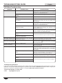
TROUBLESHOOTING GUIDE
COLD Mode Troubleshooting
Troubleshooting Questions?
If you continue to have problems resolving an issue, please contact the nearest Authorized Hatco Service Agency or Hatco for
assistance. To locate the nearest Service Agency, log onto the Hatco website at www.hatcocorp.com, select the Support pull-
down menu, and click on “Find A Service Agent”; or contact the Hatco Parts and Service Team at:
Telephone:800-558-0607or414-671-6350
e-mail: [email protected]
La page est en cours de chargement...
La page est en cours de chargement...
La page est en cours de chargement...
La page est en cours de chargement...
La page est en cours de chargement...
La page est en cours de chargement...
La page est en cours de chargement...
La page est en cours de chargement...
La page est en cours de chargement...
La page est en cours de chargement...
La page est en cours de chargement...
La page est en cours de chargement...
La page est en cours de chargement...
La page est en cours de chargement...
La page est en cours de chargement...
La page est en cours de chargement...
La page est en cours de chargement...
La page est en cours de chargement...
La page est en cours de chargement...
La page est en cours de chargement...
La page est en cours de chargement...
La page est en cours de chargement...
La page est en cours de chargement...
La page est en cours de chargement...
La page est en cours de chargement...
La page est en cours de chargement...
La page est en cours de chargement...
La page est en cours de chargement...
-
 1
1
-
 2
2
-
 3
3
-
 4
4
-
 5
5
-
 6
6
-
 7
7
-
 8
8
-
 9
9
-
 10
10
-
 11
11
-
 12
12
-
 13
13
-
 14
14
-
 15
15
-
 16
16
-
 17
17
-
 18
18
-
 19
19
-
 20
20
-
 21
21
-
 22
22
-
 23
23
-
 24
24
-
 25
25
-
 26
26
-
 27
27
-
 28
28
-
 29
29
-
 30
30
-
 31
31
-
 32
32
-
 33
33
-
 34
34
-
 35
35
-
 36
36
-
 37
37
-
 38
38
-
 39
39
-
 40
40
-
 41
41
-
 42
42
-
 43
43
-
 44
44
-
 45
45
-
 46
46
-
 47
47
-
 48
48


Hatco HCWBIR, HCWBIX Series Le manuel du propriétaire
- Taper
- Le manuel du propriétaire
dans d''autres langues
Documents connexes
-
Hatco HCWBI Series Le manuel du propriétaire
-
-
-
-
-
-
-
Hatco HWBI-1D Le manuel du propriétaire
-
-
