
P/N 07.04.407.00 © 2019 Hatco Corporation
hatcocorp.com
Register Online!
(see page 2)
S’inscrire en ligne!
(voir page 26)
Do not operate this equipment unless you
have read and understood the contents
of this manual! Failure to follow the
instructions contained in this manual
may result in serious injury or death.
This manual contains important safety
information concerning the maintenance,
use, and operation of this product. If
you’re unable to understand the contents
of this manual, please bring it to the
attention of your supervisor. Keep this
manual in a safe location for future
reference.
English = p 2
WARNING
No opere este equipo al menos que haya
leído y comprendido el contenido de este
manual! Cualquier falla en el seguimiento
de las instrucciones contenidas en
este manual puede resultar en un serio
lesión o muerte. Este manual contiene
importante información sobre seguridad
concerniente al mantenimiento, uso y
operación de este producto. Si usted
no puede entender el contenido de
este manual por favor pregunte a su
supervisor. Almacenar este manual en
una localización segura para la referencia
futura.
ADVERTENCIA
Ne pas utiliser cet équipement sans avoir
lu et compris le contenu de ce manuel ! Le
non-respect des instructions contenues
dans ce manuel peut entraîner de
graves blessures ou la mort. Ce manuel
contient des informations importantes
concernant l’entretien, l’utilisation et le
fonctionnement de ce produit. Si vous ne
comprenez pas le contenu de ce manuel,
veuillez le signaler à votre supérieur.
Conservez ce manuel dans un endroit
sûr pour pouvoir vous y référer plus tard.
Français = p 26
AVERTISSEMENT
Modular Built-In Insulated Heated Wells
Puits chauffants modulaires
intégrés avec isolation
HWBI Series/Série
Installation and Operating Manual
Manuel d’installation et d’utilisation

2
Form No. HWBIM-0319
English
Important Owner Information ..............................................2
Introduction ...........................................................................2
Important Safety Information ..............................................3
Model Designation ...............................................................4
Model Description ................................................................5
Specifications .......................................................................7
Dimensions .......................................................................... 7
Plug Configurations .............................................................8
Water Supply Specifications (Auto-Fill Units) ......................8
Electrical Rating Chart .........................................................8
Installation ...........................................................................10
General .............................................................................. 10
Countertop Cutout Dimensions .........................................12
Installing a Remote Control Enclosure .............................. 14
Connecting a Drain Line ....................................................15
Operation .............................................................................16
General .............................................................................. 16
Maintenance ........................................................................17
General .............................................................................. 17
Daily Cleaning ...................................................................17
Removing Lime and Mineral Deposits ..............................17
Troubleshooting Guide ......................................................18
Options and Accessories ..................................................19
Limited Warranty ................................................................25
Authorized Parts Distributors ...........................Back Cover
IMPORTANT OWNER INFORMATION
Record the model number, serial number, voltage, and purchase
date of the unit in the spaces below (specification label located
on the side of the unit). Please have this information available
when calling Hatco for service assistance.
Model No. _______________________________________
Serial No. ________________________________________
Voltage __________________________________________
Date of Purchase __________________________________
Register your unit!
Completing online warranty registration will prevent delay in
obtaining warranty coverage. Access the Hatco website at
www.hatcocorp.com, select the Support pull-down menu,
and click on “Warranty”.
Business
Hours: 7:00 am to 5:00 pm Monday–Friday,
Central Time (CT)
(Summer Hours: June to September—
7:00 am to 5:00 pm Monday–Thursday
7:00 am to 4:00 pm Friday)
Telephone: 800-558-0607; 414-671-6350
E-mail: [email protected]
24 Hour 7 Day Parts and Service
Assistance available in the United States
and Canada by calling 800-558-0607.
Additional information can be found by visiting our web site at
www.hatcocorp.com.
INTRODUCTION
Hatco Modular Built-In Heated Wells are specially designed to
hold heated foods at safe serving temperatures. Designed for
dry or wet applications, the wells are available in a variety of
pan combinations — all heated with a long-life heating element
that is covered by a 2 year part warranty. The metal sheathed
heating element is controlled by a remote thermostat. Heat is
distributed evenly throughout the heavy gauge stainless steel
construction to ensure hot food. The design allows for easy
maintenance and durable performance. Standard units are UL
approved and equipped with a remote control enclosure.
Units are equipped with EZ lock mounting hardware, mounting
studs, or pre-drilled mounting holes. Controls include individual
lighted power switches and thermostat controls that retain
temperature settings. One year parts and on-site labor warranty
is standard.
Hatco Modular Built-In Heated Wells are a product of extensive
research and field testing. The materials used were selected
for maximum durability, attractive appearance, and optimum
performance. Every unit is inspected and tested thoroughly prior
to shipment.
This manual provides the installation, safety, and operating
instructions for the Modular Built-In Heated Wells. Hatco
recommends all installation, operating, and safety instructions
appearing in this manual be read prior to installation or
operation of the unit.
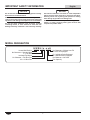
Safety information that appears in this manual is identified by
the following signal word panels:
WARNING
WARNING indicates a hazardous situation which, if not
avoided, could result in death or serious injury.
CAUTION
CAUTION indicates a hazardous situation which, if not
avoided, could result in minor or moderate injury.
NOTICE
NOTICE is used to address practices not related to
personal injury.
CONTENTS

Form No. HWBIM-0319
3
English
IMPORTANT SAFETY INFORMATION
WARNING
ELECTRIC SHOCK HAZARD:
• Turn power switch OFF, disconnect unit from power
source, and allow unit to cool before performing any
maintenance or cleaning.
• DO NOT submerge or saturate with water. Unit is not
waterproof. Do not operate if unit has been submerged
or saturated with water.
• Unit is not weatherproof. Locate unit indoors where
ambient air temperature is a minimum of 70°F (21°C).
• Remote control enclosure must be mounted on vertical
wall and installed in vertical position. Mounting remote
control enclosure in horizontal position may result in
collection of liquids and lead to electric shock.
• Operating voltage of remote control enclosure water valve
exceeds 50 V (extra low voltage). Enclosure is marked
with the following hazard identification symbol:
• DO NOT use unit to melt or hold ice. Doing so may
cause condensation, creating an electrical hazard and
causing personal injury and/or damage to unit. Damage
caused by condensation is not covered by warranty.
• For non auto-fill units, turn off unit when filling with
water and avoid splashing.
• Do not clean unit when it is energized or hot.
• This unit is not “jet-proof” construction. Do not use
jet-clean spray to clean this unit.
• This unit must be serviced by qualified personnel only.
Service by unqualified personnel may lead to electric
shock or burn.
• Use only Genuine Hatco Replacement Parts when
service is required. Failure to use Genuine Hatco
Replacement Parts will void all warranties and may
subject operators of the equipment to hazardous
electrical voltage, resulting in electrical shock or burn.
Genuine Hatco Replacement Parts are specified to
operate safely in the environments in which they are
used. Some aftermarket or generic replacement parts
do not have the characteristics that will allow them to
operate safely in Hatco equipment.
FIRE HAZARD:
• Installunitwithaminimumof3-1/2″(89mm)ofspace
from bottom of unit to all combustible surfaces to
prevent combustion.
• Unit must be installed using ribbon putty gasket
between the unit and the installation surface per
installation instructions (refer to the INSTALLATION
section of this manual).
• Do not use flammable cleaning solutions to clean this
unit.
This unit must be installed by qualified, trained installers.
Installation must conform to all local electrical and
plumbing codes. Check with local plumbing and electrical
inspectors for proper procedures and codes.
This unit is not intended for use by children or persons
with reduced physical, sensory, or mental capabilities.
Ensure proper supervision of children and keep them
away from unit.
WARNING
Make sure all operators have been instructed on the safe
and proper use of unit.
Make sure food product has been heated to the proper
food-safe temperature before placing in the unit. Failure
to heat food product properly may result in serious health
risks. This unit is for holding pre-heated food product only.
Hatco Corporation is not responsible for actual food
product serving temperature. It is the responsibility of the
user to ensure that food product is held and served at a
safe temperature.
This unit has no “user-serviceable” parts. If service is required
on this unit, contact an Authorized Hatco Service Agent or
contact the Hatco Service Department at 800-558-0607 or
414-671-6350.
CAUTION
BURN HAZARD:
• Some exterior surfaces on unit will get hot. Use caution
when touching these areas.
• Drain water may reach temperatures in excess of 200°F
(93°C). Use appropriate plumbing materials when
installing drain.
• DO NOT clean unit while it contains any food product.
Remove food product and allow unit to cool completely
before cleaning.
Locate unit at proper counter height in an area that is
convenient for use. The location should be strong enough
to support the weight of unit and contents.
Auto-Fill units must be installed with adequate backflow
protection and must conform with all federal, state, and
local codes.
NOTICE
Auto-fill units supplied with water from a reverse osmosis
(RO) system (or similiar water filtration system) must be
installed with an operating reminerialization sytem to
ensure proper operation. Failure to do so may cause unit to
overfill. Damage caused by overfilling is not covered under
warranty.
Units are voltage-specific. Refer to specification label for
electrical requirements before beginning installation.
Standard and approved manufacturing oils may smoke up
to 30 minutes during initial startup. This is a temporary
condition. Operate unit without food product until smoke
dissipates.
Do not locate unit in an area subject to excessive
temperatures or grease from grills, fryers, etc. Excessive
temperatures could cause damage to unit.
Unit is designed and recommended for use in or on
metallic countertops. Damage to any countertop material
is not covered under the Hatco warranty. For other
surfaces, verify with manufacturer that material is suitable
for prolonged temperatures up to 200°F (93°C).
Read the following important safety information before using this equipment to avoid serious
injury or death and to avoid damage to equipment or property.

4
Form No. HWBIM-0319
English
NOTICE
Do not use steel wool or metal scouring pad for cleaning.
Steel wool will scratch the finish.
Use non-abrasive cleaners and cloths only. Abrasive
cleaners and cloths could scratch finish of unit, marring its
appearance and making it susceptible to soil accumulation.
Do not use harsh chemicals such as bleach, cleaners
containing bleach, or oven cleaners to clean this unit.
Damage caused by chemicals is not covered by warranty.
NOTICE
Unit must be allowed to cool down to room temperature
before changing from wet-to-dry or dry-to-wet operation.
Allowing unit to run dry during wet operation or adding
water during dry operation will damage unit.
Drain sealants must have temperature rating of 500°F
(260°C) or higher. Incoming water pipes must be FDA
compliant for potable water.
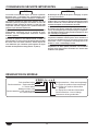
H W B L I x - x x A
Heated Well Built-In
No Character = Without Auto-Fill
A = Auto-Fill Equipped
No Character = Full-Size Pan
43 = 4/3 Size Pan
D = Individual Drain Equipped
M = Manifold Drain Equipped
No Character = No Drain
Insulated Top Mount
No Character = Standard Watt
L = Low Watt
Pan Capacity
MODEL DESIGNATION
IMPORTANT SAFETY INFORMATION

Form No. HWBIM-0319
5
English
MODEL DESCRIPTION
All Models
All Modular Built-In Heated Well units are reliable and versatile.
Each unit has an insulated, stainless steel and aluminized steel
housing with a metal sheathed heating element available in
low or standard wattage. The heating element is controlled
with a thermostatic temperature control and a lighted POWER
ON/OFF switch housed in a remote control enclosure. The
remote control enclosure is connected to the unit with a 6′
(1829 mm) flexible conduit assembly. Modular Built-In Heated
Wells are hardwired directly to a power source for a secure and
cord-free serving area.
All models are equipped with EZ locking hardware and designed
to be mounted to the topside of a non-combustible countertop.
Modular Built-In Heated Wells are designed, manufactured,
and tested to maintain safe food holding temperatures.
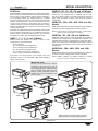
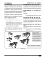
HWBI-1, -2, -3, -4, -5, and -6 Models
HWBI models are capable of holding a variety of pan
combinations in each heated well.
• One full size pan
• Two 1/2-size pans with adapter bars.
• Three 1/3-size pans with adapter bars.
• Six 1/6-size pans with adapter bars.
• Two 7 quart round pans with adapter top.
• Three 4 quart round pans with adapter top.
Food Pans, Pan Support Bars, and Adapter Tops sold
separately (refer to the OPTIONS AND ACCESSORIES
section in this manual).
HWBI-1D, 2D, -3D, -4D, -5D, and -6D Models
HWBI-XD models have the same capabilities as the HWBI-X
models but are equipped with a separate drain in each
well. Each drain includes a 3/4″ NPT drain fitting and a flat
drain screen that allows for pans to stay level for consistent
temperatures.
HWBI-1DA, -2DA, -3DA, -4DA, -5DA, and -6DA
Models
HWBI-XDA models have the same capabilities as the HWBI-XD
models but are also equipped with the Auto-Fill feature.
NOTE: Auto-Fill will fill only the left-hand well. To fill all wells,
drains must be connected to a manifold.
HWBI-2M, -3M, -4M, -5M, and -6M Models
HWBI-XM models have the same capabilities as the HWBI-X
models but are equipped with a manifold drain assembly. The
manifold drain assembly is equipped with a 1″ NPT drain fitting.
Each well connected to the manifold drain assembly includes a
flat drain screen that allows for pans to stay level for consistent
temperatures.
HWBI-2MA, -3MA, -4MA, -5MA, and -6MA
Models
HWBI-XMA models have the same capabilities as the HWBI-XM
models but are also equipped with the Auto-Fill feature.
NOTE: HWBI-4, HWBI-5, and HWBI-6 models for Canada
have all controls in a single control enclosure.
*
*
*
HWBI-4
HWBI-5
HWBI-6
HWBI-3
HWBI-2
HWBI-1
HWBI Models
* HWBI-4, HWBI-5, and HWBI-6 models for Canada
require all controls in a single control enclosure.
IMPORTANT NOTE
Remote control enclosures must be
mounted on the front of the unit to
ensure the controls correspond with the
correct wells (the front of the unit is the
side the conduit enters under the unit).
Remote control enclosures cannot be
rewired and must be installed in the
proper location.

6
Form No. HWBIM-0319
English
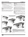
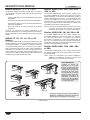
HWBI43-1, -2, -3, -4, -5, and -6 Models
HWBI43-X models are capable of holding a variety of pan
combinations listed below.
• One full size pan and one 1/3 size pan with adapter bar.
• Four 1/3 size pans with adapter bars.
• Two 1/2 size pans and one 1/3 size pan with adapter bars.
• Two 11 quart (10 L) round pans with adapter top.
Pans, Covers, Adapter Bars, and Adapter Tops sold separately
(see the OPTIONS AND ACCESSORIES section for details).
HWBI43-1D, -2D, -3D, -4D, -5D, and -6D
Models
HWBI-43-XD models have the same capabilities as the
HWBI43-X but with a separate drain in each well. The drain
includes a 3/4″ NPT drain fitting and flat drain screen that
allows for pans to stay level for consistent temperatures.
HWBI43-1DA, -2DA, -3DA, -4DA, -5DA, and
-6DA Models
HWBI43-XDA models have the same capabilities as the
HWBI43-XD but with the optional Auto-Fill feature. The Auto-Fill
feature fills and maintains the proper level of water in the well
automatically.
NOTE: Auto-Fill will fill only the left-hand well. To fill all wells,
drains must be connected to a manifold.
HWBI43-2M, -3M, -4M, -5M, and -6M Models
HWBI43-XM models have the same capabilities as the
HWBI43-X models but are equipped with a manifold drain
assembly. The manifold drain assembly is equipped with a 1″
NPT drain fitting. Each well connected to the manifold drain
assembly includes a flat drain screen that allows for pans to
stay level for consistent temperatures.
HWBI43-2MA, -3MA, -4MA, -5MA, and -6MA
Models
HWBI43-XMA models have the same capabilities as the
HWBI43-XM models but are also equipped with the Auto-Fill feature.
NOTE: HWBI43-4, HWBI43-5, and HWBI43-6 models for
Canada have all controls in a single control enclosure.
MODEL DESCRIPTION
*
*
*
HWBI43-4
HWBI43-5
HWBI43-6
HWBI43-3
HWBI43-2
HWBI43-1
HWBI43 Models
IMPORTANT NOTE
Remote control enclosures must be mounted on the front of the
unit to ensure the controls correspond with the correct wells (the
front of the unit is the side the conduit enters under the unit).
Remote control enclosures cannot be rewired and must be
installed in the proper location.
* HWBI43-4, HWBI43-5, and HWBI43-6
models for Canada require all controls
in a single control enclosure.

Form No. HWBIM-0319
7
English
Model Width (A) Depth (B)* Height (C)
HWBI-1 15-1/2″
(394 mm)
23-5/8″
(600 mm)
9-5/8″
(244 mm)
HWBI-2 29-1/2″
(749 mm)
23-5/8″
(600 mm)
9-5/8″
(244 mm)
HWBI-3 43-1/2″
(1105 mm)
23-5/8″
(600 mm)
9-5/8″
(244 mm)
HWBI-4 57-1/2″
(1461 mm)
23-5/8″
(600 mm)
9-5/8″
(244 mm)
HWBI-5 71-1/2″
(1816 mm)
23-5/8″
(600 mm)
9-5/8″
(244 mm)
HWBI-6 85-1/2″
(2172 mm)
23-5/8″
(600 mm)
9-5/8″
(244 mm)
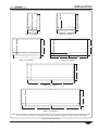
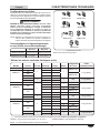
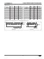
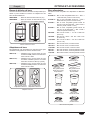
SPECIFICATIONS
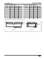
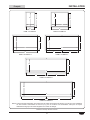
Dimensions - HWBI-X Models
Side View
A
B
C
7-9/16″
(192 mm)
3″
(76 mm)
Side Drains
7″
(178 mm)
Front View
14″
(356 mm)
Bottom
Drains
5/16″
(8 mm)
Flange
* Units with over-sized bezel option have a Depth (B) of 27″ (686 mm).
Model Width (A) Depth (B)* Height (C)
HWBI43-1 15-1/2″
(394 mm)
30-3/8″
(772 mm)
9-5/8″
(244 mm)
HWBI43-2 29-1/2″
(749 mm)
30-3/8″
(772 mm)
9-5/8″
(244 mm)
HWBI43-3 43-1/2″
(1105 mm)
30-3/8″
(772 mm)
9-5/8″
(244 mm)
HWBI43-4 57-1/2″
(1461 mm)
30-3/8″
(772 mm)
9-5/8″
(244 mm)
HWBI43-5 71-1/2″
(1816 mm)
30-3/8″
(772 mm)
9-5/8″
(244 mm)
HWBI43-6 85-1/2″
(2172 mm)
30-3/8″
(772 mm)
9-5/8″
(244 mm)
Dimensions - HWBI43-X Models

8
Form No. HWBIM-0319
English
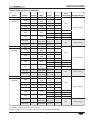
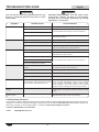
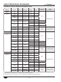
Model Voltage Circuit Watts Amps Phase
Plug
Configuration
Shipping
Weight*
HWBLI-1
120
1
750 6.3
1
NEMA 5-15P
38 lbs. (17 kg)
HWBI-1 and
HWBI43-1**
120
1215 10.1
208
1215 5.8
NEMA 6-15P
240
1215 5.1
220–230
1
1215–1328 5.5–5.8
1 N/A 38 lbs. (17 kg)
230–240
1116–1215 4.9–5.1
HWBLI-2
120
1
1500 12.5
1
NEMA 5-20P
73 lbs. (33 kg)
HWBI-2 and
HWBI43-2
208
2415 11.6
NEMA 6-15P
2415 10.1
3 N/A
240
2415 10.1
1 NEMA 6-15P
2415 8.7
3 N/A
220–230
1
2415–2640 11.0–11.5
1 N/A 73 lbs. (33 kg)
230–240
2218–2415 9.6–10.1
HWBLI-3
120
1
2250 18.8
1
NEMA 5-30P
103 lbs. (47 kg)
HWBI-3 and
HWBI43-3
208
3615 17.4
NEMA 6-30P
3615 10.1
3 N/A
240
3615 15.1
1 NEMA 6-20P
3615 8.8
3 N/A
220–230
1
3615–3951 16.4–17.2
1 N/A 103 lbs. (47 kg)
230–240
3320–3615 14.4–15.1
Minimum Maximum
Water Pressure 25 psi (172 kPa) 100 psi (689 kPa)
Water Temperature 35°F (2°C) 110°F (43°C)
SPECIFICATIONS
Water Supply Specifications (Auto-Fill Units)
NEMA 6-50P
NEMA 6-30P
NEMA 6-20P
NEMA 6-15P
NEMA 5-15P
NEMA 5-20P
NEMA 5-30P
Plug Configurations
NOTE: Receptacle not supplied by Hatco.
Plug Configurations
Some units are supplied from the factory with an electrical
cord and plug installed. Plugs are supplied according to the
application. Refer to the OPTIONS AND ACCESSORIES
section for more information.
WARNING
ELECTRIC SHOCK HAZARD: Plug unit into a properly
grounded electrical receptacle of the correct voltage,
size, and plug configuration. If plug and receptacle do not
match, contact a qualified electrician to determine and
install proper voltage and size electrical receptacle.
NOTE: Specification label located on side of the unit. See
label for serial number and verification of unit electrical
information.
Electrical Rating Chart
The shaded areas contain electrical information for International models only.
NOTE: Shipping weight includes packaging. * Add 3 lbs. (1.4 kg) for “D” and “DA” models.
** Model HWBI43-1 not available in 120V.

Form No. HWBIM-0319
9
English
Model Voltage Circuit Watts Amps Phase
Plug
Configuration Shipping Weight*
HWBLI-4
120
1 3000 25.0 1
N/A
132 lbs. (60 kg)
HWBI-4 and
HWBI43-4
208 ‡
1
2
2415
2400
11.6
11.5
1
1
208
1 4815 15.8 3
240 ‡
1
2
2415
2400
10.1
10.0
1
1
240
1 4815 13.7 3
208 † 1 4815
23.1 1 NEMA 6-30P
15.8 3 N/A
240 † 1 4815
20.1 1 NEMA 6-30P
13.7 3 N/A
220–230 ‡
1
2
2415–2639
2400–2623
11.0–11.5
10.9–11.4
1
1
N/A 132 lbs. (60 kg)
230–240 ‡
1
2
2218–2415
2204–2400
9.6–10.1
9.6–10.0
1
1
HWBLI-5
120
1 3750 31.3 1
N/A
167 lbs. (76 kg)
HWBI-5 and
HWBI43-5
208 ‡
1
2
2415
3600
11.6
17.3
1
1
208 1 6015 20.1 3
240 ‡
1
2
2415
3600
10.1
15.0
1
1
240 1 6015 17.4 3
208 † 1 6015
28.9 1 NEMA 6-50P
20.1 3 N/A
240 † 1 6015
25.1 1 NEMA 6-50P
17.4 3 N/A
220–230 ‡
1
2
2415–2640
3600–3935
11.0–11.5
16.4–17.1
1
1
N/A 167 lbs. (76 kg)
230–240 ‡
1
2
2218–2415
3306–3600
9.6–10.1
14.4–15.0
1
1
HWBLI-6
120
1 4500 37.5 1
N/A
190 lbs. (86 kg)
HWBI-6 and
HWBI43-6
208 ‡
1
2
3615
3600
17.4
17.3
1
1
208 1 7215 20.1 3
240 ‡
1
2
3615
3600
15.1
15.0
1
1
240 1 7215 17.4 3
208 † 1 7215
34.7 1 NEMA 6-50P
20.1 3 N/A
240 † 1 7215
30.1 1 NEMA 6-50P
17.4 3 N/A
220–230 ‡
1
2
3615–3951
3600–3934
16.5–17.2
16.4–17.1
1
1
N/A 190 lbs. (86 kg)
230–240 ‡
1
2
3320–3615
3306–3600
14.4–15.1
14.4–15.0
1
1
SPECIFICATIONS
Electrical Rating Chart (Continued)
† Canadian unit with single remote control enclosure.
‡ Unit with multiple circuit connections. Each circuit requires a separate circuit breaker.

10
Form No. HWBIM-0319
English
INSTALLATION
General
Modular Built-In Heated Well units are shipped from the factory
with most components assembled and ready for use. Use the
following procedures to install the unit.
NOTE: All Modular Built-In Heated Wells require the control
enclosure to be remote mounted.
NOTE: Make sure the installation location provides enough
room for the remote mounted control enclosure,
electrical connections, and plumbing connections.
WARNING
ELECTRIC SHOCK HAZARD: Unit is not weatherproof.
Locate unit indoors where ambient air temperature is a
minimum of 70°F (21°C).
FIRE HAZARD:
• Installunitwithaminimumof3-1/2″(89mm)ofspace
from bottom of unit to all combustible surfaces to
prevent combustion.
• Unit must be installed using ribbon putty gasket
between the unit and the installation surface per
installation instructions.
This unit must be installed by qualified, trained installers.
Installation must conform to all local electrical and
plumbing codes. Check with local plumbing and electrical
inspectors for proper procedures and codes.
CAUTION
Locate unit at proper counter height in an area that is
convenient for use. The location should be strong enough
to support the weight of unit and contents.
NOTICE
Do not locate unit in an area subject to excessive
temperatures or grease from grills, fryers, etc. Excessive
temperatures could cause damage to the unit.
Unit is designed and recommended for use in or on
metallic countertops. Damage to any countertop material
is not covered under the Hatco warranty. For other
surfaces, verify with manufacturer that material is suitable
for prolonged temperatures up to 200°F (93°C).
1. Remove the unit from the box.
NOTE: To prevent delay in obtaining warranty coverage,
complete online warranty registration. See the
IMPORTANT OWNER INFORMATION section for
details.
2. Remove tape and protective packaging from all surfaces
of unit.
NOTE: A qualified electrician should connect the unit(s) to a
power source. A qualified plumber should connect the
water supply and drain(s).
3. Install the unit in the desired location. Use the appropriate
procedure in this section for the style of mounting chosen
at order.
NOTE: HWBI43 models can be installed using the EZ Locking
Mounting System only.
4. Install the remote control enclosure (refer to the “Installing a
Remote Control Enclosure” procedure later in this section).
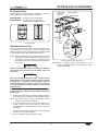
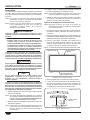
EZ Locking Mounting System
NOTE: Cut the opening for both the unit and the control
enclosure(s) before placing unit into the countertop
opening.
1. Cut the appropriate opening in the countertop.
Refer to the “Countertop Cutout Dimensions” chart in this
section.
2. Cut the appropriate opening for the control enclosure(s)
Refer to the “Control Enclosure Cutout Dimensions” chart
in this section.
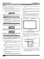
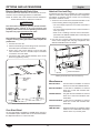
3. Place ribbon putty gasket around the cutout edge of the
countertop. Make sure the ribbon putty gasket overhangs
the cutout edge or seal unit with silicone adhesive.
NOTE: A roll of ribbon putty gasket material is supplied with the
unit.
Ribbon Putty
Gasket
Cutout edge
of countertop.
Countertop
Installing Ribbon Putty Gasket
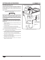
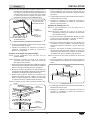
4. Place the unit into the countertop opening.
5. Using a screwdriver, rotate the unit’s EZ locking tabs
outward to secure the unit to the underside of the
countertop. Rotate as many tabs as needed to secure the
unit to the countertop.
EZ Locking
Tab
Countertop
EZ Locking Tabs
NOTE: The Hatco EZ locking tabs work on countertops
that have a maximum thickness of 3/16″ (5 mm).
For countertops 3/16″–2″ (5–51 mm) thick, use an
appropriate number of accessory thick counter adapter
brackets (HWB-MNT-REC).

Form No. HWBIM-0319
11
English
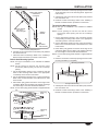
INSTALLATION
Insert bracket
into slot in
EZ locking tab.
Bolt
(included
with bracket)
Adapter
Bracket
Tighten bolt against
underside of
countertop.
Thick Countertop Adapter Bracket
6. Carefully trim and remove the excess ribbon putty material
from around the unit.
7. Install the control enclosure(s). Refer to the “Installing a
Remote Control Enclosure” procedure in this section.
Built-In Stud Mounting System
NOTE: This type of installation is not available for HWBI43
models.
NOTE: Cut the opening for both the unit and the control
enclosure(s) before placing unit into the countertop
opening.
1. Cut the appropriate opening in the countertop and drill
holes for the mounting studs. Refer to the appropriate
“Countertop Cutout” chart in this section.
2. Cut the appropriate opening for the control enclosure(s)
Refer to the “Control Enclosure Cutout Dimensions” chart
in this section.
3. Place ribbon putty gasket around the cutout edge of the
countertop. Make sure the ribbon putty gasket overhangs
the cutout edge or seal unit with silicone adhesive.
NOTE: A roll of ribbon putty gasket material is supplied with the
unit.
Mounting
Stud
Mounting
Stud
Mounting
Nut
Built-In Stud Mounting
4. Place the unit into the countertop opening and secure with
1/4-20 mounting nuts on the mounting studs. Tighten the
nuts securely.
5. Carefully trim and remove the excess ribbon putty material
from around the unit.
6. Install the control enclosure(s). Refer to the “Installing a
Remote Control Enclosure” procedure in this section.
Through-Hole Mounting System
NOTE: This type of installation is not available for HWBI43
models.
NOTE: Cut the opening for both the unit and the control
enclosure(s) before placing unit into the countertop
opening.
1. Cut the appropriate opening in the countertop and drill
corresponding mounting holes. Refer to the appropriate
“Countertop Cutout” chart in this section.
2. Cut the appropriate opening for the control enclosure(s)
Refer to the “Control Enclosure Cutout Dimensions” chart
in this section.
3. Place ribbon putty gasket around the cutout edge of the
countertop. Make sure the ribbon putty gasket overhangs
the cutout edge or seal unit with silicone adhesive.
NOTE: A roll of ribbon putty gasket material is supplied with the
unit.
4. Place the unit into the countertop opening and secure with
mounting hardware (not supplied).
Mounting Hardware
Through-Hole Mounting
5. Carefully trim and remove the excess ribbon putty material
from around the unit.
6. Install the control enclosure(s). Refer to the “Installing a
Remote Control Enclosure” procedure in this section.

12
Form No. HWBIM-0319
English
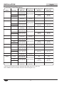
Model Mounting
Unit Opening
Width (A)
Unit Opening
Depth (B)
Mounting Holes
Width (C)
Mounting Holes
Depth (D)*
HWBI-1 EZ Tab 14-1/8″–14-3/8″
(359–365 mm)
22-1/4″–22-1/2″
(565–572 mm)
N/A N/A
Stud
14-1/8″–14-5/16″
(359–364 mm)
14-3/4″
(375 mm)
22-7/8″
(581 mm)
Through-Hole
HWBI43-1 EZ Tab 14-1/4″
(362 mm)
29-1/8″
(740 mm)
N/A N/A
HWBI-2 EZ Tab 28-1/8″–28-3/8″
(714–721 mm)
22-1/4″–22-1/2″
(565–572 mm)
N/A N/A
Stud
28-1/8″–28-5/16″
(714–719 mm)
28-3/4″
(730 mm)
22-7/8″
(581 mm)
Through-Hole
HWBI43-2 EZ Tab 28-1/4″
(718 mm)
29-1/8″
(740 mm)
N/A N/A
HWBI-3 EZ Tab 42-1/8″–42-3/8″
(1070–1076 mm)
22-1/4″–22-1/2″
(565–572 mm)
N/A N/A
Stud
42-1/8″–42-5/16″
(1070–1075 mm)
42-3/4″
(1086 mm)
22-7/8″
(581 mm)
Through-Hole
HWBI43-3 EZ Tab 42-1/4″
(1073 mm)
29-1/8″
(740 mm)
N/A N/A
HWBI-4 EZ Tab 56-1/8″–56-3/8″
(1425–1432 mm)
22-1/4″–22-1/2″
(565–572 mm)
N/A N/A
Stud
56-1/8″–56-5/16″
(1425–1432 mm)
28-3/8″
(721 mm)
22-7/8″
(581 mm)
Through-Hole
HWBI43-4 EZ Tab 56-1/4″
(1429 mm)
29-1/8″
(740 mm)
N/A N/A
HWBI-5 EZ Tab 70-1/8″–70-3/8″
(1781–1787 mm)
22-1/4″–22-1/2″
(565–572 mm)
N/A N/A
Stud
70-1/8″–70-5/16″
(1781–1786 mm)
35-3/8″
(899 mm)
22-7/8″
(581 mm)
Through-Hole
HWBI43-5 EZ Tab 70-1/4″
(1784 mm)
29-1/8″
(740 mm)
N/A N/A
HWBI-6 EZ Tab 84-1/8″–84-3/8″
(2137–2143 mm)
22-1/4″–22-1/2″
(565–572 mm)
N/A N/A
Stud 84-1/8″–84-5/16″
(2137–2142 mm)
42-3/8″
(1076 mm)
22-7/8″
(581 mm)
Through-Hole
HWBI43-6 EZ Tab 84-1/4″
(2140 mm)
29-1/8″
(740 mm)
N/A N/A
INSTALLATION
* Optional over-sized bezel units have a Mounting Hole Depth (D) of 26-1/4″ (667 mm).
NOTE: HWBI43 models are available with the EZ Tab mounting option only.
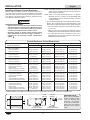
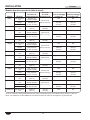
Countertop Cutout Dimensions

Form No. HWBIM-0319
13
English
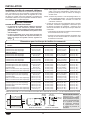
INSTALLATION
NOTE: Required minimum clearance below countertop cutout is 13-1/8″ (333 mm) when installing around combustible surfaces
and 11″ (279 mm) around non-combustible surfaces. Allow additional clearance for units equipped with a drain.
HWBI-1 and HWBI43-1
HWBI-3 and HWBI43-3
HWBI-4 and HWBI43-4
HWBI-6 and HWBI43-6
B
A
B
A
B
A
B
A
C
C
C C
C C
D
HWBI-2 and HWBI43-2
B
A
C
D
D
D
D
HWBI-5 and HWBI43-5
B
A
C
C
D
Countertop Cutout Dimensions

14
Form No. HWBIM-0319
English
Control Enclosure Cutout Dimensions
Opening Dimensions Screw Hole Dimensions
Model and Enclosure (A) (B) (C) (D)
HWBI-1 and HWBI43-1
Control w/Auto-Fill 10-1/8″ (257 mm) 4-3/4″ (121 mm) 10-7/16″ (265 mm) 2-1/2″ (64 mm)
Control w/o Auto-Fill 5-3/4″ (146 mm) 4-3/4″ (121 mm) 6-1/16″ (154 mm) 2-1/2″ (64 mm)
HWBI-2 and HWBI43-2
Control w/Auto-Fill 12-3/8″ (314 mm) 4-3/4″ (121 mm) 12-11/16″ (322 mm) 2-1/2″ (64 mm)
Control w/o Auto-Fill 8″ (203 mm) 4-3/4″ (121 mm) 8-5/16″ (211 mm) 2-1/2″ (64 mm)
HWBI-3 and HWBI43-3
Control w/ Auto-Fill 14-5/8″ (371 mm) 4-3/4″ (121 mm) 14-15/16″ (379 mm) 2-1/2″ (64 mm)
Control w/o Auto-Fill 10-1/4″ (260 mm) 4-3/4″ (121 mm) 10-9/16″ (268 mm) 2-1/2″ (64 mm)
HWBI-4 and HWBI43-4
Left Control w/ Auto-Fill 12-3/8″ (314 mm) 4-3/4″ (121 mm) 12-11/16″ (322 mm) 2-1/2″ (64 mm)
Left Control w/o Auto-Fill 8″ (203 mm) 4-3/4″ (121 mm) 8-5/16″ (211 mm) 2-1/2″ (64 mm)
Right Control 8″ (203 mm) 4-3/4″ (121 mm) 8-5/16″ (211 mm) 2-1/2″ (64 mm)
Control Enclosure w/ Auto-Fill * 16-7/8″ (429 mm) 4-3/4″ (121 mm) 17-3/16″ (437 mm) 2-1/2″ (64 mm)
Control Enclosure w/o Auto-Fill * 12-1/2″ (318 mm) 4-3/4″ (121 mm) 12-13/16 (325 mm) 2-1/2″ (64 mm)
HWBI-5 and HWBI43-5
Left Control w/ Auto-Fill 12-3/8″ (314 mm) 4-3/4″ (121 mm) 12-11/16″ (322 mm) 2-1/2″ (64 mm)
Left Control w/o Auto-Fill 8″ (203 mm) 4-3/4″ (121 mm) 8-5/16″ (211 mm) 2-1/2″ (64 mm)
Right Control 10-1/4″ (260 mm) 4-3/4″ (121 mm) 10-9/16″ (268 mm) 2-1/2″ (64 mm)
Control Enclosure w/ Auto-Fill * 19-1/8″ (486 mm) 4-3/4″ (121 mm) 19-7/16″ (494 mm) 2-1/2″ (64 mm)
Control Enclosure w/o Auto-Fill * 14-3/4″ (375 mm) 4-3/4″ (121 mm) 15-1/16″ (383 mm) 2-1/2″ (64 mm)
HWBI-6 and HWBI43-6
Left Control w/ Auto-Fill 14-5/8″ (371 mm) 4-3/4″ (121 mm) 14-7/8″ (378 mm) 2-1/2″ (64 mm)
Left Control w/o Auto-Fill 10-1/4″ (260 mm) 4-3/4″ (121 mm) 10-1/2″ (267 mm) 2-1/2″ (64 mm)
Right Control 10-1/4″ (260 mm) 4-3/4″ (121 mm) 10-1/2″ (267 mm) 2-1/2″ (64 mm)
Control Enclosure w/ Auto-Fill * 21-3/8″ (543 mm) 4-3/4″ (121 mm) 21-5/8″ (549 mm) 2-1/2″ (64 mm)
Control Enclosure w/o Auto-Fill * 17″ (432 mm) 4-3/4″ (121 mm) 17-1/4″ (438 mm) 2-1/2″ (64 mm)
INSTALLATION
Installing a Remote Control Enclosure
Remote control enclosures must be mounted on the front of
the unit to ensure the controls correspond with the correct wells
(the front of the unit is the side the conduit enters under the
unit). Remote control enclosures cannot be rewired and must
be installed in the proper location.
WARNING
ELECTRIC SHOCK HAZARD:
• Remote control enclosure must be mounted on vertical
wall and installed in vertical position. Mounting remote
control enclosure in horizontal position may result in
collection of liquids and lead to electric shock.
• Operating voltage of remote control enclosure water
valve exceeds 50 V (extra low voltage). Enclosure is
marked with the following hazard identification
symbol:
NOTE: A qualified electrician should connect the unit(s) to a
power source. A qualified plumber should connect the
water supply and drain(s).
NOTE: Refer to the “Side Mounted Auto-Fill” or “Bottom
Mounted Auto-Fill” procedure in the OPTIONS AND
ACCESSORIES section before installing a Remote
Control Enclosure.
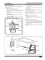
1. Cut and drill the appropriate holes in the mounting surface.
Refer to the “Control Enclosure Cutout Dimensions” chart
below for the cutout dimensions for each control enclosure.
• The cutout depth required for all control enclosures is
5″ (127 mm).
• Make sure to have enough space inside the cutout if
installing with conduit on the side of the control enclosure.
• For units with two control enclosures: If the unit is
equipped with Auto-Fill, each enclosure cutout size will
be different (see chart below).
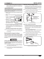
Control Enclosure Cutout Dimensions
* HWBI-4, HWBI-5, and HWBI-6 units with all controls in a single control enclosure — required for Canadian units.
A
C
D
B
Front View –
Control Enclosure
Side View –
Control Enclosure
2-11/16″
(68 mm)
1-7/8″
(48 mm)
1-1/8″
(29 mm)
IMPORTANT NOTE:
Make sure the installation
location provides enough
room for electrical and
plumbing connections
to the control enclosure.
Follow local and national
plumbing and electrical
codes.

Form No. HWBIM-0319
15
English
INSTALLATION
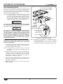
2. Remove the trim cover from the control enclosure.
3. Position the control enclosure into the opening through the
backside.
4. Secure the control enclosure to the mounting surface
using screws (#8 sheet metal screw supplied).
Typical knockout
locations for power
source connection.
Control
Enclosure
5. Connect the proper power
source to the mounted remote
control enclosure. Wiring
must be fixed a minimum of 4″
(102 mm) from bottom of
well(s).
6. Connect the water supply to
the optional Auto-Fill system,
if equipped. Refer to the
“Side Mounted Auto-Fill” or
“Drain Mounted Auto-Fill” procedure in the OPTIONS AND
ACCESSORIES section.
7. Reinstall the trim cover. Seal the trim cover to the
mounting surface with silicone adhesive.
NOTE: Standard UL approved units are equipped with a 72″
(1829 mm) flexible conduit connected to the remote
control enclosure.
Connecting A Drain Line
After installing a drain- or manifold-equipped unit into the
countertop, use the following procedure to connect the
unit to the on-site drain line. Refer to the OPTIONS AND
ACCESSORIES section for external manifold drain with valves
information.
CAUTION
BURN HAZARD: Drain water may reach temperatures
in excess of 200°F (93°C). Use appropriate plumbing
materials when installing drain.
NOTE: Consult a licensed plumbing contractor for proper drain
installation that conforms to local plumbing codes.
NOTE: Approved air gap or other back-flow prevention device
must be installed by a licensed plumber, if required.
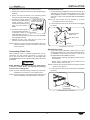
Individual Drain Units
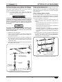
1. Connect drain pipe (supplied by others) from the 3/4″ NPT
drain fitting(s) on the bottom of the well(s) to a 3/4″ drain
valve (supplied by others or available as an accessory
from Hatco—refer to the OPTIONS AND ACCESSORIES
section).
NOTE: The drain valve(s) must be installed in an easily
accessible location for the operator.
2. Connect the drain valve to the on-site drain line (supplied
by others).
To drain
3/4″ Drain Valve
3/4″ Drain Fitting
(inside unit)
14″
(356 mm)
on
center
Individual Drain Connection
Manifold Drain Units
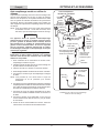
1. Connect drain pipe (supplied by others) from the 1″ NPT
manifold drain fitting to a 1″ drain valve (supplied by others
or available as an accessory from Hatco — refer to the
OPTIONS AND ACCESSORIES section).
• Side/End Drain: manifold drain fitting located on either
end of the unit.
• Bottom Drain: manifold drain fitting located on the
bottom at either end of the unit.
NOTE: The drain valve must be installed in an easily accessible
location for the operator.
2. Connect the drain valve to the on-site drain line (supplied
by others).
1″ Drain Valve
1″ Manifold
Drain Fitting
To drain
Side Manifold Drain Connection

16
Form No. HWBIM-0319
English
OPERATION
General
Use the following procedures to operate the Modular Built-In
Heated Wells.
WARNING
Read all safety messages in the Important Safety
Information section before operating this equipment.
ELECTRIC SHOCK HAZARD:
• DO NOT use unit to melt or hold ice. Doing so may
cause condensation, creating an electrical hazard and
causing personal injury and/or damage to unit. Damage
caused by condensation is not covered by warranty.
• For units without Auto-Fill, turn off unit when filling
with water and avoid splashing.
NOTICE
Standard and approved manufacturing oils may smoke up to
30 minutes during initial startup. This is a temporary condition.
Operate unit without food product until smoke dissipates.
Unit must be allowed to cool down to room temperature
before changing from wet-to-dry or dry-to-wet operation.
Allowing unit to run dry during wet operation or adding
water during dry operation will damage unit.
Hatco Modular Built-In Heated Wells are designed for WET
or DRY operation. Hatco recommends wet operation for
consistent food heating. If the unit is operating wet and runs
dry, turn it off and allow to cool before adding water.
Startup
1. Prepare the heated wells for operation.
• If using the wells for dry operation, make sure the wells
are clean and dry.
• If using the wells for wet operation without Auto-Fill,
make sure the drain valve is closed (if equipped) and
manually fill the wells with hot tap water until the water
is a maximum of 1-1/4″ (32 mm) deep.
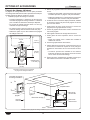
• If the unit is equipped with the Auto-Fill option, make sure
the drain valve is closed and go to step 2 in this procedure.
2. Place an empty pan in the well or cover the well with a lid.
This step is recommended to speed up pre-heating and
reach operating temperature.
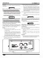
3. Move the Power I/O (on/off) switches to the I (on) position.
The indicator light on each switch glows when it is on.
• If the unit is equipped with the Auto-Fill option, the far
left Power I/O (on/off) switch will activate the Auto-Fill
system when it is moved to the I (on) position. The wells
will fill with water until the water reaches the water level
sensor in the far left well. During operation, the Auto-Fill
system will maintain the water level automatically using
the water level sensor.
NOTE: For 4, 5, and 6 well units equipped with Auto-Fill, turn
on the left-hand control first, then turn on the right-hand
control.
4. Turn the Temperature Control Knobs to the desired safe
food temperature.
WARNING
Hatco Corporation is not responsible for actual food
product serving temperature. It is the responsibility of the
user to ensure that food product is held and served at a
safe temperature.
5. Allow the unit to preheat for approximately 30 minutes.
CAUTION
BURN HAZARD: Some exterior surfaces on the unit will get
hot. Use caution when touching these areas.
Food Warming
Place the appropriate size food pans with pre-heated food
product into the heated wells.
• Always use a food pan. Do not place food directly into the
heated well.
• Stir thick food items frequently to keep food heated
uniformly.
• Keep pans covered to maintain food quality and
temperature.
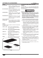
Shutdown
1. Move the Power I/O (on/off) switches to the O (off) position.
The indicator light on the switches will shut off and the
Auto-Fill system will be deactivated (if equipped).
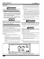
Temperature Control
Knob
Power I/O (on/off)
Switch
HWBI-2DA Control Enclosure (unit with drains and Auto-Fill)

Form No. HWBIM-0319
17
English
MAINTENANCE
General
The Hatco Modular Built-In Heated Wells are designed for
maximum durability and performance, with minimum maintenance.
WARNING
ELECTRIC SHOCK HAZARD:
• Turn power switch OFF, disconnect unit from power
source, and allow unit to cool before performing any
maintenance or cleaning.
• DO NOT submerge or saturate with water. Unit is not
waterproof. Do not operate if unit has been submerged
or saturated with water.
• Do not clean unit when it is energized or hot.
• This unit is not “jet-proof” construction. Do not use
jet-clean spray to clean this unit.
FIRE HAZARD: Do not use flammable cleaning solutions
to clean this unit.
This unit has no “user-serviceable” parts. If service
is required on this unit, contact an Authorized Hatco
Service Agent or contact the Hatco Service Department at
800-558-0607 or 414-671-6350.
NOTICE
Do not use steel wool or metal scouring pad for cleaning.
Steel wool will scratch the finish.
Use non-abrasive cleaners and cloths only. Abrasive
cleaners and cloths could scratch finish of unit, marring its
appearance and making it susceptible to soil accumulation.
Do not use harsh chemicals such as bleach, cleaners
containing bleach, or oven cleaners to clean this unit.
Damage caused by chemicals is not covered by warranty.
Daily Cleaning
To preserve the finish of the heated well(s), perform the
following cleaning procedure daily.
1. Move the Power I/O (on/off) switches to the O (off) position
and allow the unit to cool.
2. Remove and wash any pans and adapters.
3. Open the drain valve (if equipped) or manually remove
water from the well(s) if used for wet operation.
4. Wipe down the entire unit using a clean cloth or sponge
and mild detergent.
5. Use a plastic scouring pad to remove any hardened food
particles or mineral deposits.
6. Rinse the well(s) thoroughly with hot water to remove all
detergent residue.
7. Wipe dry the entire unit using a non-abrasive, dry cloth.
Removing Lime and Mineral Deposits
Use the following procedure whenever lime or scale is seen
accumulating on the sides of the heated wells.
1. Move the Power I/O (on/off) switches to the O (off) position
and allow the unit to cool.
2. Remove and wash any pans and adapters.
3. Open the drain valve (if equipped) or manually remove
water from the well(s) if used for wet operation.
4. Close the drain valve(s).
5. Fill the water reservoir with a mixture of 75% water and
25% white vinegar. Do not use flavored vinegar.
6. Move the Power I/O (on/off) switches to the I (on) position
and heat the solution to the maximum temperature of
190°F (88°C).
7. Move the Power I/O (on/off) switches to the O (off) position
and cover the well(s).
8. Allow the solution to soak for at least one hour or overnight
for heavy buildup.
9. Drain or remove the water/cleaning solution from the
well(s).
10. Scrub the well(s) with a plastic scouring pad.
11. Rinse the well(s) thoroughly with hot water.
12. Wipe dry the entire unit using a non-abrasive, dry cloth.
NOTE: Heavy scale buildup may require additional treatments.

18
Form No. HWBIM-0319
English
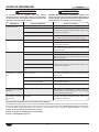
Symptom Probable Cause Corrective Action
Heated wells not hot enough. Temperature Control set too low. Adjust Temperature Control to a higher setting.
Heating element not working.
Contact Authorized Service Agent or Hatco for assistance.
Temperature Control not working properly.
Voltage supplied is incorrect. Verify correct voltage is supplied to unit. Low supply voltage will
cause improper heating.
Heated wells too hot. Temperature Control set too high. Adjust Temperature Control to a lower setting.
Temperature Control not working properly. Contact Authorized Service Agent or Hatco for assistance.
Voltage supplied is incorrect. Verify correct voltage is supplied to unit. High supply voltage will
cause unit to overheat and my damage the unit.
No heat. Unit turned off. Move the Power I/O (on/off) switches to the I (on) position
Circuit breaker tripped. Reset circuit breaker. If circuit breaker continues to trip, contact
Authorized Service Agent or Hatco.
Temperature Control not working properly.
Contact Authorized Service Agent or Hatco for assistance.
Heating element not working.
Power I/O (on/off) switch not working.
Auto-Fill system not working. Water level sensor is dirty and not “sensing”
properly.
Perform the “Cleaning” procedure in the Maintenance section
with special focus on the water level sensor.
Water not supplied to fill valve. Verify water supply is correctly installed.
Water fill valve malfunctioning. Contact Authorized Service Agent or Hatco for assistance.
Left-hand well not turned on. Turn on well.
Unit is overfilling with water. Water level sensor is not “sensing” minerals in
the water supply. This is typically due to reverse
osmosis water or similar filtration process.
Auto-fill units supplied with water from a reverse osmosis (RO)
system (or similiar water filtration system) must be installed
with an operating reminerialization sytem to assure proper
operation. Failure to do so may cause the unit to overfill.
Damage caused by overfilling is not covered under warranty.
Food product not holding hot
enough.
Well being operated as a dry unit. Allow unit to cool and fill with the appropriate amount of water
for wet operation. Wet operation promotes consistent hot food
holding.
Temperature control knobs
heat wrong well.
Control enclosure installed incorrectly. Install control enclosure on the front side of the unit. Contact
Authorized Service Agent or Hatco for assistance.
TROUBLESHOOTING GUIDE
WARNING
This unit must be serviced by qualified personnel only.
Service by unqualified personnel may lead to electric
shock or burn.
WARNING
ELECTRIC SHOCK HAZARD: Turn OFF power switch,
unplug power cord/turn off power at circuit breaker,
and allow unit to cool before performing any cleaning,
adjustments, or maintenance.
Troubleshooting Questions?
If you continue to have problems resolving an issue, please contact the nearest Authorized Hatco Service Agency or Hatco for
assistance. To locate the nearest Service Agency, log onto the Hatco website at www.hatcocorp.com, select the Support pull-
down menu, and click on “Find A Service Agent”; or contact the Hatco Parts and Service Team at:
Telephone: 800-558-0607 or 414-671-6350
e-mail: [email protected]

Form No. HWBIM-0319
19
English
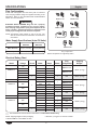
OPTIONS AND ACCESSORIES
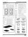
Adapter Tops
The following adapter tops are available to allow rectangular
heated wells to hold round pans.
HWB-2-7Q .......... Adapter to convert HWBI Series heated
wells to hold two 7-quart (7 l) round pans.
HWB-3-4Q .......... Adapter to convert HWBI Series heated
wells to hold three 4-quart (4 l) round pans.
HWB-2-11Q ........... Adapter to convert HWBI43 Series heated
well to hold two 11-quart round pans.
7 Quart Adapter Top4 Quart Adapter Top
Adapter Tops
Trivets
Stainless steel or nickel-plated trivets are available in various
sizes.
TRIVET (1/4)SS......Quarter-size stainless steel trivet —
8-1/2″W x 4-1/2″D (216 x 114 mm)
TRIVET (1/2)SS......Half-size stainless steel trivet —
10-3/16″W x 7-5/8″D (259 x 194 mm)
TRIVET SS .............Full size stainless steel trivet —
10-1/8″W x 18″D (257 x 457 mm)
TRIVET (1/2) ..........Half-size nickel-plated trivet —
10-3/16″W x 7-5/8″D (259 x 194 mm)
TRIVET ...................Full size nickel-plated trivet —
10-1/8″W x 18″D (257 x 457 mm)
1/2 Trivet
Full Trivet
1/4 Trivet
Trivets
Food Pans
Stainless steel food pans are available in various sizes.
ST PAN 1/3 ........ Third-size stainless steel pan — 12-3/4″W x
6-7/8″D x 2-1/2″H (324 x 175 x 64 mm)
ST PAN 1/2 ........ Half-size stainless steel pan — 12-3/4″W x
10-3/8″D x 2-1/2″H (324 x 264 x 64 mm)
ST PAN 2 ........... Full size stainless steel pan at 2-1/2″
(64 mm) deep — 12-3/4″W x 20-3/4″D x
2-1/2″H (324 x 527 x 64 mm)
ST PAN 4 ........... Full size stainless steel pan at 4″
(102 mm) deep — 12-3/4″W x 20-3/4″D x 4″H
(324 x 527 x 102 mm)
4QT-PAN ............ 4 quart (4 l) round pan — 6-3/4″ dia x 8″H
(171 x 203 mm)
7QT-PAN ............ 7 quart (7 l) round pan — 8-11/16″ dia x 8″H
(221 x 203 mm)
11QT-PAN .......... 11 quart (10 l) round pan — 12-1/4″ dia x 8″H
(311 x 203 mm)
4QT-LID-1 .......... 4 quart (4 l) round, notched lid
7QT-LID-1 .......... 7 quart (7 l) round, notched lid
11QT-LID-1......... 11 quart (10 l) round, notched lid
4QT-LID .............. 4 quart (4 l) round, hinged and notched lid
7QT-LID .............. 7 quart (7 l) round, hinged and notched lid
11QT-LID ............ 11 quart (10 l) round, hinged and notched lid
4 Quart (4 l)
Round Pan
4 Quart (4 l)
Notched Lid
7 Quart (7 l)
Notched Lid
4 Quart (4 l)
Hinged Lid
7 Quart (7 l)
Hinged Lid
7 Quart (7 l)
Round Pan
1/2 Pan,
2-1/2″ (64 mm) Deep
1/3 Pan,
2-1/2″ (64 mm) Deep
Full Pan,
2-1/2″ (64 mm) Deep
Full Pan,
4″ (102 mm) Deep
Stainless Steel Food Pans

20
Form No. HWBIM-0319
English
OPTIONS AND ACCESSORIES
Exterior Manifold with Drain Valve
An exterior drain valve manifold is an accessory for two to six-
well units. Use the following procedure to install drains.
NOTE: An exterior drain valve manifold cannot be installed on
models without drains or with built-in manifolds.
WARNING
This unit must be installed by qualified, trained installers.
Installation must conform to all local electrical and
plumbing codes. Check with local plumbing and electrical
inspectors for proper procedures and codes.
NOTICE
Drain sealants must have temperature rating of 500°F (260°C)
or higher. Incoming water pipes must be FDA compliant for
potable water.
1. Unscrew the union nuts.
2. Attach all male fittings to drain fittings under each drain.
Use teflon tape on threaded connections.
3. Screw union nuts to drain fittings to secure the drain
valve manifold to the unit. Use teflon tape on threaded
connections. Check for leaks.
4. Connect the drain valve manifold assembly to the on-site
drain line (supplied by others).
3/4″
Drain
Valve
Male Fitting
To Drain
Fitting
Union
Nut
External Manifold Drain with Valves Connection
Over-Sized Bezel
An over-sized bezel is available for all HWBI series units as a
non-retrofittable option. Models with an over-sized bezel match
the depth dimensions of a Hatco cold well.
Attached Cord and Plug
An attached cord and plug is available as a factory-installed
option for models with a single phase electrical configuration
and without an extended control conduit. Use the following
procedure to install the control.
1. Secure the control enclosure to the desired location on the
control mounting bracket using supplied screws.
• The cutout depth required for all control enclosures is
5″ (127 mm).
• The cutout height required for this control enclosure is
4-3/4″ (121 mm).
• Refer to the “Installing a Remote Control Enclosure”
procedure in the INSTALLATION section if mounting the
control enclosure remotely.
2. Plug unit into a properly grounded electrical receptacle
of the correct voltage, size, and plug configuration. See
SPECIFICATIONS section for details.
Screws
Control Mounting
Bracket
Control Enclosure
Installing Control Enclosure with Cord and Plug
Miscellaneous
BALLVALVE3/4 ........ 3/4″ ball valve for installation on external
drain line of units with individual drains.
BALLVALVE1INCH .. 1″ ball valve for installation on external
drain line of units with manifold drain
assemblies.
GATEVALVE3/4IN ..... 3/4″ gate valve for installation on external
drain line of units with individual drain
assemblies.
GATEVALVE1INCH .. 1″ gate valve for installation on external
drain line of units with manifold drain
assemblies.
Adapter Bracket
HWB-MNT-REC ....... Adapter brackets (8) for installing heated
wells into non-combustible countertops
that are 3/16″–2″ (5–52 mm) thick.
La page charge ...
La page charge ...
La page charge ...
La page charge ...
La page charge ...
La page charge ...
La page charge ...
La page charge ...
La page charge ...
La page charge ...
La page charge ...
La page charge ...
La page charge ...
La page charge ...
La page charge ...
La page charge ...
La page charge ...
La page charge ...
La page charge ...
La page charge ...
La page charge ...
La page charge ...
La page charge ...
La page charge ...
La page charge ...
La page charge ...
La page charge ...
La page charge ...
La page charge ...
La page charge ...
La page charge ...
La page charge ...
-
 1
1
-
 2
2
-
 3
3
-
 4
4
-
 5
5
-
 6
6
-
 7
7
-
 8
8
-
 9
9
-
 10
10
-
 11
11
-
 12
12
-
 13
13
-
 14
14
-
 15
15
-
 16
16
-
 17
17
-
 18
18
-
 19
19
-
 20
20
-
 21
21
-
 22
22
-
 23
23
-
 24
24
-
 25
25
-
 26
26
-
 27
27
-
 28
28
-
 29
29
-
 30
30
-
 31
31
-
 32
32
-
 33
33
-
 34
34
-
 35
35
-
 36
36
-
 37
37
-
 38
38
-
 39
39
-
 40
40
-
 41
41
-
 42
42
-
 43
43
-
 44
44
-
 45
45
-
 46
46
-
 47
47
-
 48
48
-
 49
49
-
 50
50
-
 51
51
-
 52
52


dans d''autres langues
- English: Hatco HWBI-1D Owner's manual
Documents connexes
-
Hatco IWEL Series Manuel utilisateur
-
Hatco HWB-FUL, HWBI-FUL, HWBIB-FUL, HWB-43, HWB-xQT, HWBI-xQT Series Le manuel du propriétaire
-
-
-
-
-
-
Hatco CHW Series Manuel utilisateur
-
-