La page est en cours de chargement...

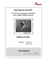
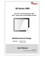
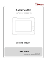
Full IP66 Aluminum
Flat Touch Series Panel PC
R19IHAT-66EX for ATEX Zone II and C1D2
R19IHAT-66EX
User Manual
Document Version 11.0
Document Part No. PPM201404282

2
R19IHAT-66EX User Manual
Contents
Preface 3
Chapter 1: Introduction 7
1.1 Overview 7
1.2 Features 7
1.3 Package Contents 8
1.4 Product Overview 9
1.5 Front Buttons 10
Chapter 2: Getting Started 11
2.1 Turning On Your Device 11
2.2 Adjusting the LCD Display Brightness 12
2.3 Turning Off Your Device 12
Chapter 3: Installation 13
3.1 Wiring Requirements 13
3.2 Wiring 14
3.3 Pin Assignments 16
Chapter 3: Mounting Solution 21
3.1 Clamp Mount 21
3.2 VESA Mount 22
Chapter 4: Windows 7 Driver Installation 23
4.1 Chipset Driver Installation 23
4.2 Graphic Driver Installation 25
4.3 USB 3.0 Driver Installation 27
4.4 Ethernet Driver Installation 30
4.5 Audio Driver Installation 31
4.6 Fintek COM Port Driver Installation 32
4.7 Intel Management Engine Software Installation 35
4.8 HotTab Driver and AP Installation 37
4.9 Hottab Utility 43
4.9.1 System information menu 44
4.9.2 Hottab Shortcut Setting 44
4.10 Touch Lock Setting 46
4.11 Brightness Adjustment 47
Appendix 48
Appendix A: Hardware Specifications 48
Appendix B: Cleaning the Monitor 41
Appendix B: Statement of Regulatory Approval 41

3
Preface
Preface
Copyright Notice
No part of this document may be reproduced, copied, translated, or transmitted in any form or by
any means, electronic or mechanical, for any purpose, without the prior written permission of the
original manufacturer.
Trademark Acknowledgement
Brand and product names are trademarks or registered trademarks of their respective owners.
Disclaimer
We reserves the right to make changes, without notice, to any product, including circuits and/or
software described or contained in this manual in order to improve design and/or performance. We
assume no responsibility or liability for the use of the described product(s), conveys no license or title
under any patent, copyright, or masks work rights to these products, and makes no representations or
warranties that these products are free from patent, copyright, or mask work right infringement,
unless otherwise specified. Applications that are described in this manual are for illustration purposes
only. We make no representation or warranty that such application will be suitable for the specified
use without further testing or modification.
Warranty
Our warranty that each of its products will be free from material and workmanship defects for a period
of one year from the invoice date. If the customer discovers a defect, we will, at its option, repair or
replace the defective product at no charge to the customer, provided it is returned during the warranty
period of one year, with transportation charges prepaid. The returned product must be properly
packaged in the original packaging to obtain warranty service.
If the serial number and the product shipping data differ by over 30 days, the in-warranty service
will be made according to the shipping date. In the serial numbers the third and fourth two digits
give the year of manufacture, and the fifth digit means the month (e. g., with A for October, B for
November and C for December).
For example, the serial number 1W08Axxxxxxxx means October of year 2008.

4
R19IHAT-66EX User Manual
Customer Service
We provide service guide for any problem as follow steps: First, visit the website of our distributor to
find the update information about the product. Second, contact with your distributor, sales
representative, or our customer service center for technical support if you need additional assistance.
You may have the following information ready before you call:
•
Product serial number
•
Peripheral attachments
•
Software (OS, version, application software, etc.)
•
Description of complete problem
•
The exact wording of any error messages
In addition, free technical support is available from our engineers every business day. We are
always ready to give advice on application requirements or specific information on the
installation and operation of any of our products. Please do not hesitate to call or e-mail us.
Safety Information
WARNING!
Always completely disconnect the power cord from your chassis whenever
you work with the hardware. Do not make connections while the power is
on. Sensitive electronic components can be damaged by sudden power
surges. Only experienced electronics personnel should open the PC
chassis.
CAUTION!
Always ground yourself to remove any static charge before touching the
CPU card. Modern electronic devices are very sensitive to static electric
charges. As a safety precaution, use a grounding wrist strap at all times.
Place all electronic components in a static-dissipative surface or static-shielded bag when
they are not in the chassis.
Safety Precautions
•
Please read these safety instructions carefully.
•
Please keep this user’s manual for later reference.
•
Please disconnect this equipment from any AC outlet before cleaning. Do not use liquid
or spray detergents for cleaning. Use a damp cloth.
•
Do not touch the LCD panel surface with sharp or hard objects.
•
For pluggable equipment, the power outlet must be installed near the
equipment and must be easily accessible.
•
Keep this equipment away from humidity.
•
Place this equipment on a reliable surface during installation. Dropping it or letting it
fall could cause damage.
•
The openings on the enclosure are for air convection. Protect the equipment from overheating.
DO NOT COVER THE OPENINGS.
•
Make sure the voltage of the power source is correct before connecting the equipment to

5
Preface
the power outlet.
•
Position the power cord so that people cannot step on it. Do not place anything
over the power cord.
•
All cautions and warnings on the equipment should be noted.
•
If the equipment is not used for a long time, disconnect it from the power source
to avoid damage by transient over-voltage.
•
Never pour any liquid into an opening. This could cause fire or electrical shock.
•
Never open the equipment. For safety reasons, only qualified service personnel should
open the equipment.
•
This equipment is designed to be used in restricted access location. Only service persons or
trained persons are allowed to access this equipment.
•
If any of the following situations arises, get the equipment checked by service personnel:
The power cord or plug is damaged.
Liquid has penetrated into the equipment.
The equipment has been exposed to moisture.
The equipment does not work well, or you cannot get it to work according to the user’s
manual.
The equipment has been dropped and damaged.
The equipment has obvious signs of breakage.
•
Do not leave this equipment in an uncontrolled environment where the storage temperature is
below
-20°C (-4°F) or above 70°C (158°F). It may damage the equipment.
•
Ne laissez pas ce matériel dans un environnement non contrôlé où la température de
stockage est inférieure à -20 ° C ( -4 ° F ) ou au-dessus de 70 ° C ( 158 ° F ) . Il peut
endommager le matériel.
•
CAUTION – Use recommended mounting apparatus to avoid risk of injury.
•
ATTENTION - Utilisez recommandé appareil de montage pour éviter les risques de blessure.
•
WARNING – Only use the connection cords which comes along with the product,
when in doubt, please contact the manufacturer.
•
ATTENTION - Utilisez uniquement les cordons de connexion qui vient avec le produit
, en cas de doute , s'il vous plaît contactez le fabricant.
•
Provision shall be made to provide transient protection device to be set at a level not
exceeding 140% of the rated voltage at the power supply terminals of the apparatus.
•
Des dispositions seront prises pour fournir dispositif de protection contre les transitoires à
être fixé à un niveau ne dépassant pas 140 % de la tension nominale aux bornes
d'alimentation de l'appareil.
•
WARNING – Explosion Hazard – Do not disconnect equipment unless power has been
switched off or the area is known to be non-hazardous.
•
AVERTISSEMENT - Risque d'explosion - Ne débranchez pas l'équipement que
l'alimentation est coupée ou que la zone est connue pour être non dangereux
•
WARNING – Explosion Hazard – Do not apply any audio connectors in Hazardous Location.
•
AVERTISSEMENT - Risque d'explosion - Ne pas appliquer tous les connecteurs audio
dans des environnements dangereux .
•
WARNING – The equipment should be adequately protected from direct light when
installed indoor or outdoor.

6
R19IHAT-66EX User Manual
•
AVERTISSEMENT - L'équipement doit être adéquatement protégé de la lumière
directe lors de l'installation intérieure ou extérieure.
•
WARNING – DO NOT OPEN, MAINTAIN OR SERVICE IN AN AREA WHERE AN
EXPLOSIVE ATMOSPHERE MAY BE PRESENT.
•
AVERTISSEMENT - NE PAS OUVRIR , maintenir ou SERVICE DANS UN ENDROIT
OÙ UNE ATMOSPHERE EXPLOSIVE PEUT ETRE PRESENTE .
•
THIS EQUIPMENT IS SUITABLE FOR USE IN CLASS I, DIVISION 2, GROUPS A, B, C, D
OR NON-HAZARDOUS LOCATIONS ONLY.
•
Cet équipement est utilisable en Classe I, Division 2, Groupes A,
B , C , D LIEUX OU non dangereux.
•
WARNING - EXPLOSION HAZARD – SUBSTITUTION OF COMPONENTS MAY IMPAIR
SUITABILITY FOR CLASS I, DIVISION 2;
•
AVERTISSEMENT - RISQUE D'EXPLOSION - substitution de composants peut nuire à la conformité
Classe I, Division 2 ;
•
WARNING - EXPLOSION HAZARD - DO NOT REPLACE PARTS UNLESS POWER HAS BEEN
SWITCHED OFF OR THE AREA IS KNOWN TO BE NON-HAZARDOUS;
•
AVERTISSEMENT - RISQUE D'EXPLOSION - NE PAS remplacer les pièces que l'alimentation est
coupée ou que la zone est connue pour être non dangereux;
•
WARNING - EXPLOSION HAZARD - DO NOT DISCONNECT EQUIPMENT UNLESS
POWER HAS BEEN SWITCHED OFF OR THE AREA IS KNOWN TO BE NON-
HAZARDOUS;
•
AVERTISSEMENT - RISQUE D'EXPLOSION - NE PAS déconnecter l'équipement que
l'alimentation est Coupée ou la région est connue pour être non dangereux;
•
WARNING - Do not use USB Port while the hazardous atmosphere is present.
•
AVERTISSEMENT - Ne pas utiliser le port USB tandis que l'atmosphère dangereuse est présente.
Specific Conditions of Use
Contradicts IEC 60079-0:2011 clause 8.3 for EPL Gc
WARNING – In locations where high external humidity and internal temperature variations
(e.g. frequent on-off cycles) may cause condensation inside the equipment, the interior
should be periodically inspected.
When installed, the equipment shall be subjected to an electric strength test using a test
voltage of 500 Vac applied between the circuit and earth for 60 s. Alternatively, a voltage of
20% higher may be applied for 1 s. There shall be no evidence of flashover or breakdown
and the maximum current flowing shall not exceed 5 mA.
When the device is mounted in a hazardous area, connection and disconnection of the
connectors while live is only permitted if the potentially explosive atmosphere is shown to be
absent.
The “9-36” Vdc rated supply shall be protected such that transients are limited to a maximum
of 60Vac or 85 Vdc; no such protection is required for the signal lines.
When the equipment is installed in a location where the ambient temperature is expected to
exceed 55ºC, the cable shall have a temperature rating of 85ºC minimum.
General Guideline
It is recommended to reboot the device when some functions are defect or inactive. If it still
can't solve the problems please contact your dealer or agent.

7
Chapter 1: Introduction
Chapter 1: Introduction
1.1 Overview
Class1 Division2 certification for equipment was created to ensure employee safety in explosive
atmospheres. Today many countries have made it a requirement for organizations operating in certain
industries to use equipment that meets the regulatory compliance. This includes technologies used in
potentially explosive atmospheres. The Winmate 19” HazLoc PPC is the first of its kind to offer the Class1
Division2 certification, ensuring safe and reliable data collection and processing in Hazardous Locations.
This Panel PC features robust processing power with the 2.6GHz Intel Haswell Core i5-4300U. The panel
PC also offers brilliant visibility with its true flat design, transflective sunlight-viewable, projected
capacitive touchscreen with 1280 x 1024 pixel resolution, all in a compact form factor
1.2 Features
•
Intel® Haswell Core i5-4300U, turbo max 2.6 GHz
•
19” SXGA High brightness panel, 800 nits
•
Sunlight readable, transflective, projected capacitive touch LCD panel
•
Fanless, streamlined enclosure for highly efficient heat dissipation
•
Front side buttons, one dedicated button to enable/disable touch screen interface
•
Built in to withstand extreme temperatures -40 to 70 deg. C with built in intelligent heater and
wide range temperature memory parts
•
9-36 V DC input with isolation (There is no tolerance for the DC input voltage)
•
Operable in 5-95% humidity level

8
R19IHAT-66EX User Manual
1.3 Package Contents
Before using this Panel PC, please make sure that all the items listed below are present in your package:
Standard Accessories:
Before using this Panel PC, please make sure that all the items listed below are present in your package:
Panel PC
24V 150W AC to DC
Power adapter
(for Testing only)
Power cord
Open wire power cable
LAN + COM combo cable
Manual & Driver DVD
VESA Mounting
Screws
Mounting Clips & Screws
3 Pins Terminal Block For
Power
8 Pins Terminal Block For
LAN
4 Pins Terminal
Block For USB
10 Pins Terminal Block
For COM
Touch Driver CD
(C1D2 Version)

9
Chapter 1: Introduction
Optional Accessories:
Wi-Fi Antenna extension
cable (Optional)
Side Handle
(Optional)
Note: All cables are for testing only, Do Not use these cables under Hazardous area.
1.4 Product Overview
(Unit: mm)
Front View

10
R19IHAT-66EX User Manual
1.5 Front Buttons
Front Button & LED Indicators
Power on/off
Increase the brightness of the Panel
Decrease the brightness of the Panel
Suspend the touch’s function temporarily
Programmable function key configured by Hot Tab Utility
Button Type
Function

11
Chapter 2: Getting Started
Chapter 2: Getting Started
2.1 Turning On Your Device
1.
Remove the I/O protection cover plate.
2.
Connect the Power adapter to the device.
3.
Plug the power adapter power cord to an electrical outlet.
4.
Touch the Power button on the front to turn on the device.
Note
When the system hangs, press the Reset button to restart the device.
Please make sure the unit is grounded to earth before operation

12
R19IHAT-66EX User Manual
2.2 Adjusting the LCD Display Brightness
1. Use the OSD membrane buttons on the front bottom side
to increase / decrease the display brightness.
2.3 Turning Off Your Device
To shut down your device, do the following: Tap Start ( ) > Shut down.
Wait for your Panel PC to completely turn off before disconnecting the power cord (if necessary).
Brightness
Up
Brightness
Down

13
Chapter 3: Installation
Chapter 3: Installation
3.1 Wiring Requirements
The following common safety precautions should be observed before installing any electronic device:
Strive to use separate, non-intersecting paths to route power and networking wires. If
power wiring and device wiring paths must cross make sure the wires are perpendicular
at the intersection point.
Keep the wires separated according to interface. The rule of thumb is that wiring
that shares similar electrical characteristics may be bundled together.
Do not bundle input wiring with output wiring. Keep them separate.
When necessary, it is strongly advised that you label wiring to all devices in the system.
ATTENTION
Do not run signal or communication wiring and power wiring in the same conduit. To
avoid interference, wires with different signal characteristics (i.e., different interfaces)
should be routed separately.
Be sure to disconnect the power cord before installing and/or wiring your device.
Verify the maximum possible current for each wire gauge, especially for the
power cords. Observe all electrical codes dictating the maximum current
allowable for each wire gauge.
If the current goes above the maximum ratings (80 W), the wiring could
overheat, causing serious damage to your equipment.
Be careful when handling the unit. When the unit is plugged in, the internal components
generate a lot of heat which may leave the outer casing too hot to touch.

14
R19IHAT-66EX User Manual
The unit is available with different pass through glands for cable connections (required to maintain
enclosure protection rating). These glands are water and gas tight and must be tightened with a torque
described in the gland manufacturer’s instructions provided with the unit. Cables must be passed
through the glands and wired to the associated I/O connectors.
3.2 Wiring
1. Release the screws to remove the I/O protection cover and twisting the cable gland to increase gland
opening for later cable go through
MBA12-08-L13-Ex Gland
Cable range 5.4~8mm
MBA16-10-Ex Gland
Cable Range 7.5~10.2mm
USB 2.0 Type A water
proof connector
Twisting the cable gland to
increase gland opening to
let the cable go through

15
Chapter 3: Installation
2. I/O cover has been removed and internal I/O ports will be seen.
3. Loosen the cable gland and let the cable go through to connect the internal terminal block connector.
Connect to
the terminal
block
Cable goes through
cable gland

16
R19IHAT-66EX User Manual
4. Tighten the cable gland and screw the I/O protection cover plate back.
3.3 Pin Assignments
The pin assignments of the connectors are as follows:
VGA Port (Only used in safe area)
Pin
Signal Name
Pin
Signal Name
1
R_FILTER
2
G_FILTER
3
B_FILTER
4
NC
5
GND
6
GND
7
GND
8
GND
9
VGA5V
10
GND
11
NC
12
DAC_SDAT0
13
3VHSYNC0
14
3VVSYNC0
15
DAC_SCL0
Tighten the
gland
to hold the
cable

17
Chapter 3: Installation
COM Port (Only used in safe area)
USB Port (Only used in safe area)
LAN1 Port (Only used in safe area)
Power terminal block
*Power wire for VCC should be AMW 1015 18AWG 600V or above.
Pin
Signal Name
Pin
Signal Name
1
DCD
2
RXD
3
TXD
4
DTR
5
GND
6
DSR
7
RTS
8
CTS
9
RI
Pin
Signal Name
1
VCC
2
D-
3
D+
4
GND
Pin
Signal Name
Pin
Signal Name
1
MDI0_IN+
2
MDI0_IN-
3
MDI1_IN+
4
MDI2_IN+
5
MDI2_IN-
6
MDI1_IN-
7
MDI3_IN+
8
MDI3_IN-
Pin
Signal Name
1
VCC+
2
VCC-
3
GND

18
R19IHAT-66EX User Manual
To connect the Panel PC to AC power source:
1. Plug the DC Plug of AC adapter to the Panel PC DC IN Jack.
2. Connect the AC adapter to the power cord.
3. Plug the power cord to a working AC outlet. The device will boot automatically.

19
Chapter 3: Installation
To connect the Panel PC DC power source:
1. Insert the exposed wires of the DC Power Cable to the appropriate connectors on the terminal
block plug.
2. Plug the terminal block plug firmly to the DC IN Jack.
3. Connect the other end of the DC power cable (wires with lug terminals that are labeled “+” and
“–” to the terminals of the 9~36V DC Power Source. Ensure that the power connections
maintain the proper polarity.
*The wire for GND: Equipotential bonding connection facilities on the outside of electrical
equipment shall provide effective connection of a conductor with a cross-sectional area of at
least 4 mm², AMW 1015 10AWG 600V is recommended.
COM Port
Pin
Signal Name
Pin
Signal Name
1
DCD
2
RXD
3
TXD
4
DTR
5
GND
6
DSR
7
RTS
8
CTS
9
RI
10
+V5

20
R19IHAT-66EX User Manual
LAN2 Port
Ethernet connection pin Assignments for T568A
RJ4-45 Pin No.
Wire Color
10BASE-T/100 BASE -T
Signal
1000 BASE -T
Signal
1
White/Green
Transmit+
BI_DA+
2
Green
Transmit-
BI_DA-
3
White/Orange
Receive+
BI_DB+
4
Blue
Unused
BI_DC+
5
White/Blue
Unused
BI_DC-
6
Orange
Receive-
BI_DB-
7
White/Brown
Unused
BI_DD+
8
Brown
Unused
BI_DD-
Ethernet connection pin Assignments for T568B.
RJ4-45 Pin No.
Wire Color
10BASE-T/100 BASE -T
Signal
1000 BASE -T
Signal
1
White/Orange
Transmit+
BI_DA+
2
Orange
Transmit-
BI_DA-
3
White/Green
Receive+
BI_DB+
4
Blue
Unused
BI_DC+
5
White/Blue
Unused
BI_DC-
6
Green
Receive-
BI_DB-
7
White/Brown
Unused
BI_DD+
8
Brown
Unused
BI_DD-
USB Port
Note
This adapter was certified by UL, CUL TUV/GS CE, FCC, BSMI, EK, DOIR+C- TICK,
CCC, PSE.
WARNING
Ensure that the external power source is OFF before connecting or
disconnecting
the DC IN jack.
Pin
Signal Name
Pin
Signal Name
1
MDIO3-
2
MDIO3+
3
MDIO2-
4
MDIO2+
5
MDIO1-
6
MDIO1+
7
MDIO0-
8
MDIO0+
Pin
Signal Name
1
VCC
2
D-
3
D+
4
GND
/