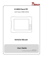
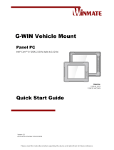
G-WIN Panel PC
Intel® Celeron® N2930 1.83 GHz
Vehicle Mount
User Guide
Version 1.1
Document Part Number: 9152111I101J

ii
G-WIN Vehicle Mount Panel PC
Preface
Copyright Notice
No part of this document may be reproduced, copied, translated, or transmitted in any form
or by any means, electronic or mechanical, for any purpose, without the prior written
permission of the original manufacturer.
Trademark Acknowledgement
Brand and product names are trademarks or registered trademarks of their respective
owners.
Disclaimer
We reserve the right to make changes, without notice, to any product, including circuits
and/or software described or contained in this manual in order to improve design and/or
performance. We assume no responsibility or liability for the use of the described product(s)
conveys no license or title under any patent, copyright, or masks work rights to these
products, and make no representations or warranties that these products are free from
patent, copyright, or mask work right infringement, unless otherwise specified. Applications
that are described in this manual are for illustration purposes only. We make no
representation or guarantee that such application will be suitable for the specified use
without further testing or modification.
Warranty
Our warranty guarantees that each of its products will be free from material and
workmanship defects for a period of one year from the invoice date. If the customer discovers
a defect, we will, at his/her option, repair or replace the defective product at no charge to the
customer, provide it is returned during the warranty period of one year, with transportation
charges prepaid. The returned product must be properly packaged in its original packaging to
obtain warranty service. If the serial number and the product shipping data differ by over 30
days, the in-warranty service will be made according to the shipping date. In the serial
numbers the third and fourth two digits give the year of manufacture, and the fifth digit
means the month (e. g., with A for October, B for November and C for December).
For example, the serial number 1W14Axxxxxxxx means October of year 2014.

G-WIN Vehicle Mount Panel PC
iii
Customer Service
We provide a service guide for any problem by the following steps: First, visit the website of
our distributor to find the update information about the product. Second, contact with your
distributor, sales representative, or our customer service center for technical support if you
need additional assistance.
You may need the following information ready before you call:
Product serial number
Software (OS, version, application software, etc.)
Description of complete problem
The exact wording of any error messages
In addition, free technical support is available from our engineers every business day. We are
always ready to give advice on application requirements or specific information on the
installation and operation of any of our products.

iv
G-WIN Vehicle Mount Panel PC
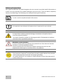
Advisory Conventions
Four types of advisories are used throughout the user manual to provide helpful information or
to alert you to the potential for hardware damage or personal injury. These are Notes, Important,
Cautions, and Warnings. The following is an example of each type of advisory.
NOTE:
A note is used to emphasize helpful information
IMPORTANT:
An important note indicates information that is important for you to know.
CAUTION/ ATTENTION
A Caution alert indicates potential damage to hardware and explains how to
avoid the potential problem.
Une alerte d’attention indique un dommage possible à l’équipement et explique
comment éviter le problème potentiel.
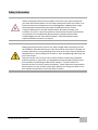
WARNING!/ AVERTISSEMENT!
An Electrical Shock Warning indicates the potential harm from electrical hazards
and how to avoid the potential problem.
Un Avertissement de Choc Électrique indique le potentiel de chocs sur des
emplacements électriques et comment éviter ces problèmes.
ALTERNATING CURRENT / MISE À LE TERRE!
The Protective Conductor Terminal (Earth Ground) symbol indicates the potential
risk of serious electrical shock due to improper grounding.
Le symbole de Mise à Terre indique le risqué potential de choc électrique grave à
la terre incorrecte.

G-WIN Vehicle Mount Panel PC
v
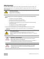
Safety Information
WARNING! / AVERTISSEMENT!
Always completely disconnect the power cord from your chassis whenever
you work with the hardware. Do not make connections while the power is on.
Sensitive electronic components can be damaged by sudden power surges.
Only experienced electronics personnel should open the PC chassis.
Toujours débrancher le cordon d’alimentation du chassis lorsque vous
travaillez sur celui-ci. Ne pas brancher de connections lorsque l’alimentation
est présente. Des composantes électroniques sensibles peuvent être
endommagées par des sauts d’alimentation. Seulement du personnel
expérimenté devrait ouvrir ces chassis.
CAUTION/ATTENTION
Always ground yourself to remove any static charge before touching the CPU
card. Modern electronic devices are very sensitive to static electric charges. As
a safety precaution, use a grounding wrist strap at all times. Place all electronic
components in a static-dissipative surface or static-shielded bag when they are
not in the chassis.
Toujours verifier votre mise à la terre afin d’éliminer toute charge statique
avant de toucher la carte CPU. Les équipements électroniques moderns sont
très sensibles aux décharges d’électricité statique. Toujours utiliser un
bracelet de mise à la terre comme précaution. Placer toutes les composantes
électroniques sur une surface conçue pour dissiper les charge, ou dans un sac
anti-statique lorsqu’elles ne sont pas dans le chassis.

vi
G-WIN Vehicle Mount Panel PC
Safety Precautions
For your safety carefully read all the safety instructions before using the device. All
cautions and warnings on the equipment should be noted. Keep this user manual for
future reference.
CAUTION/ATTENTION
Do not cover the openings!
Ne pas couvrir les ouvertures!
*Let service personnel to check the equipment in case any of the following problems
appear:
o The power cord or plug is damaged.
o Liquid has penetrated into the equipment.
o The equipment has been exposed to moisture.
o The equipment does not work well or you cannot get it to work according
to the user manual.
o The equipment has been dropped and damaged.
o The equipment has obvious signs of breakage.
Do not leave this equipment in an uncontrolled environment where the storage
temperature is below -20°C (-4°F) or above 60°C (140°F). It may damage the
equipment.
CAUTION/ATTENTION
Use the recommended mounting apparatus to avoid risk of injury.
Utiliser l’appareil de fixation recommandé pour éliminer le risque de
blessure.
WARNING! / AVERTISSEMENT!
Only use the connection cords that come with the product. When in
doubt, please contact the manufacturer.
Utiliser seulement les cordons d’alimentation fournis avec le produit. Si
vous doutez de leur provenance, contactez le manufacturier.
WARNING!/ AVERTISSEMENT!
Always ground yourself against electrostatic damage to the device.
Toujours vérifier votre mise à la terre afin que l’équipement ne se
décharge pas sur vous.

G-WIN Vehicle Mount Panel PC
vii
Important Information
Countries/ Area
Symbol
This equipment complies with essential requirements of:
European Union
Electromagnetic Compatibility Directive(2014/30/EU)
Low Voltage Directive (2014/35/EU)
Restrictions of the use of certain hazardous substances
(RoHS) Directive (2011/65/EU)
USA
FCC Part 1FCC Part 15 Subpart B Regulations Class B
Federal Communications Commission Radio Frequency Interface Statement
This device complies with part 15 FCC rules.
Operation is subject to the following two conditions:
This device may not cause harmful interference.
This device must accept any interference received including
interference that may cause undesired operation.
This equipment has been tested and found to comply with the limits for a class "B" digital
device, pursuant to part 15 of the FCC rules. These limits are designed to provide reasonable
protection against harmful interference when the equipment is operated in a commercial
environment. This equipment generates, uses, and can radiate radio frequency energy and, if
not installed and used in accordance with the instruction manual, may cause harmful
interference to radio communications. Operation of this equipment in a residential area is likely
to cause harmful interference in which case the user will be required to correct the interference
at him own expense.

viii
G-WIN Vehicle Mount Panel PC
EC Declaration of Conformity
This equipment is in conformity with the requirement of the following EU legislations and
harmonized standards. Product also complies with the Council directions.
Electromagnetic Compatibility Directive (2014/30/EU)
EN55024: 2010/ A1: 2015
o IEC61000-4-2: 2009
o IEC61000-4-3: 2006+A1: 2007+A2: 2010
o IEC61000-4-4: 2012
o IEC61000-4-5: 2014
o IEC61000-4-6: 2014
o IEC61000-4-8: 2010
o IEC61000-4-11: 2004
EN55032: 2012/AC:2013
EN61000-3-2:2014
EN61000-3-3:2013
Low Voltage Directive (2014/35/EU)
EN 60950-1:2006/A11:2009/A1:2010/A12:2011/ A2:2013

G-WIN Vehicle Mount Panel PC
ix
About This User Manual
This User Manual provides information about using the Winmate® G-WIN Vehicle Mount Panel PC.
This User Manual applies to the G-WIN Vehicle Mount Panel PC – R08IB3S-VMU1, R10IB3S-VMT2,
R10IB3S-VMP3, R10IB3S-VMP1, W12IB3S-VMM9 and R15IB3S-VMA3 (HB).
The documentation set for the G-WIN Vehicle Mount Panel PC with Intel® Celeron N2930 1.83 GHz
(Bay Trail) processor provides information for specific user needs, and includes:
G-WIN Vehicle Mount Panel PC User Manual – contains detailed description on how to use
the Panel PC, its components and features.
G-WIN Vehicle Mount Panel PC Quick Start Guide - contains detailed description on how to
use the Panel PC, its components and features.
NOTE:
Some pictures in this guide are samples and can differ from actual product.
Document Revision History
Version
Date
Note
1.0
23-Dec-2016
Initial document release
1.1
20-Jul-2019
Revise specifications

x
G-WIN Vehicle Mount Panel PC
Contents
Preface ........................................................................................................................................ ii
About This User Manual .............................................................................................................. ix
Chapter 1: Introduction .............................................................................................................. 13
1.1 Product Features ................................................................................................................ 13
1.2 Package Content ................................................................................................................ 14
1.3 Mechanical Concept........................................................................................................... 15
1.4 Physical Button and LED Indicators ................................................................................... 16
1.4.1 G-WIN Panel PC 8.4”, 10.4” and 12.1” .................................................................... 16
1.4.2 G-WIN Panel PC 15” ................................................................................................ 17
Chapter 2: Getting Started ......................................................................................................... 20
2.1 Powering On ....................................................................................................................... 20
2.1.1 AC Adapter Components ......................................................................................... 20
2.1.2 Power Considerations ............................................................................................. 21
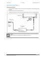
2.1.3 Connecting the Power ............................................................................................. 22
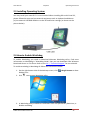
2.2 Turning On and Off ............................................................................................................ 24
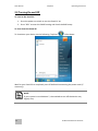
2.3 Installing Operating System ............................................................................................... 25
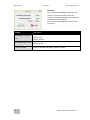
2.4 How to Enable Watchdog .................................................................................................. 25
2.5 Connectors ......................................................................................................................... 28
2.5.1 Wiring Requirements .............................................................................................. 28
2.5.2 Connector Placement .............................................................................................. 29
2.5.3 Connector Description............................................................................................. 31
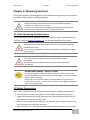
Chapter 3: Mounting Solutions ................................................................................................... 35
3.1 Cable Mounting Considerations ........................................................................................ 35
3.2 Safety Precautions ............................................................................................................. 35
3.3 Mounting Guide ................................................................................................................. 36
3.3.1 VESA Mounting ........................................................................................................ 36
3.3.2 Yoke Mounting ........................................................................................................ 38
3.3.3 Roof Mounting......................................................................................................... 41
Chapter 4: Maintenance ............................................................................................................. 45
4.1 Cleaning the Display Screen ............................................................................................... 45

G-WIN Vehicle Mount Panel PC
xi
4.2 Cleaning the Casing ............................................................................................................ 45
Chapter 5: Driver Installation ..................................................................................................... 47
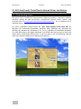
5.1 ELO AccuTouch/ CarrollTouch Infrared Driver Installation ............................................... 48
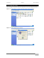
5.1.1 Downloading Drivers ............................................................................................... 48
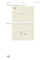
5.1.2 Configuration Utility ................................................................................................ 49
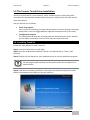
5.2 The Premier Touch Driver Installation ............................................................................... 51
5.2.1 Installing Touch Kit .................................................................................................. 51
5.2.2 Configuration Utility ................................................................................................ 52
Chapter 6: Troubleshooting ........................................................................................................ 55
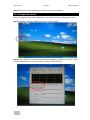
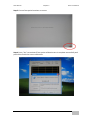
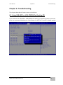
6.1 Using USB-HDD or USB-CDROM for Booting OS ................................................................ 55
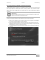
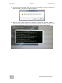
6.2 Using Recovery Wizard to Restore Computer ................................................................... 57
Chapter 7: Technical Support ..................................................................................................... 60
7.1 Software Developer Support ............................................................................................. 60
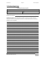
7.2 Problem Report Form ........................................................................................................ 61
Appendix A: Panel PC Selection Guide ........................................................................................ 63
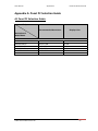
A1 Panel PC Selection Guide .................................................................................................... 63
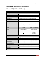
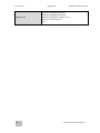
Appendix B: Motherboard Specifications .................................................................................... 65
B1 Intel IB32 (Intel Atom SoC Based) ....................................................................................... 65
Appendix C: Touchscreen ........................................................................................................... 68
C1 Overview ............................................................................................................................. 68
C2 Recommended Touch Interface ......................................................................................... 68

12
G-WIN Vehicle Mount Panel PC
Introduction
This chapter gives you product overview,
describes features and hardware specification.
You will find all accessories that come with the
Panel PC in the packing list.

User Manual Chapter 1 Introduction
G-WIN Vehicle Mount Panel PC
13
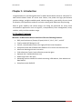
Chapter 1: Introduction
Congratulations on purchasing Winmate® G-WIN Vehicle Mount Panel PC. Winmate® G-
WIN Vehicle Mount Panel PC comes with fanless, low power but high performance
platform design, sunlight readable panel, WLAN integration, great ability for anti-shock
& vibration, IP65 protection and anti-corrosion coating with aluminum alloy housing.
Both of great mobility and robust design are fitting the demands for every harsh
environment applications such as logistics, transportation/ fleet management, heavy
vehicles, utility and also outdoor usage.
1.1 Product Features
Winmate® G-WIN Vehicle Mount Panel PCs offers the following features:
IP65-proof enclosures (Except I/O parts) for 8.4", 10.4", 12.1", and 15"
Totally sealed IP67 Design for 15"
Fanless, streamlined enclosure for highly efficient heat dissipation
Compliance with MIL-STD 810 & IEC 60068-2-27 for shock and vibration test
Aluminum Housing with anti-corrosion
5 Wire Resistive Touch / anti-reflective protection glass
Optional GPS, 3G/WLAN (Either one)
Wide range 9-36 V DC input
Mounting options suitable for vehicle mounting: VESA Mount, Yoke Mount and
Roof Mount
Compliance with EN50155

User Manual Chapter 1 Introduction
14
G-WIN Vehicle Mount Panel PC
1.2 Package Contents
Carefully remove the box and unpack your device. Please check if all the items listed
below are inside your package. If any of these items are missing or damaged contact us
immediately.
Standard factory shipment list
Panel PC
Quick Start Guide
Driver CD and User
Manual
Touch Driver CD
Varies by product
specifications
9152111I101W
IB32: 9171111I101Y
9171111T100D
3 Pin Terminal Block
Cable:94EL02X020E0
Connector:
604520105004
Package may include the following items based on your order (optional)
AC Adapter
Power Cord
WLAN Antenna
Mounting Bracket
50W:90PO12050000
80W:90PO12800000
Varies by
destination
391000020202
8.4” 99KK08Z00010
10.4”99KK00Z00010
15” 99KK15A00001

User Manual Chapter 1 Introduction
G-WIN Vehicle Mount Panel PC
15
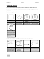
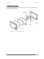
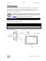
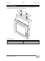
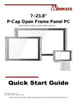
1.3 Mechanical Concept
On the picture below you can see spare parts exploded drawing of a standard G-WIN
Vehicle Mount Series Panel PC.

User Manual Chapter 1 Introduction
16
G-WIN Vehicle Mount Panel PC
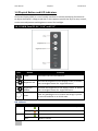
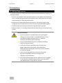
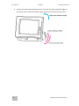
1.4 Physical Button and LED Indicators
On-Screen Display (OSD) is a user-friendly interface to remote the display function and
to adjust the display’s image properties. It also supports special Hot Keys for easy control,
such as auto-adjustment and brightness control for backlight.
1.4.1 G-WIN Panel PC 8.4”, 10.4” and 12.1”
Icon
Button
Function
Power
Turn ON or turn OFF the Panel PC.
Brightness UP
Increase the brightness of the display screen, or allows
user to navigate items of a single OSD menu.
Brightness
DOWN
Decrease the brightness of the display screen, or allows
user to navigate items of a single OSD menu.
Reset
Clear any pending errors or events and brings a system
to normal condition or an initial state.
LED Indicators
Indicator
Color
Definition
PWR
Green
Power is ON and the device functions normally
Orange
Panel PC is suspended
HDD
Green
HDD is active
OFF
HDD is inactive

User Manual Chapter 1 Introduction
G-WIN Vehicle Mount Panel PC
17
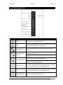
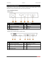
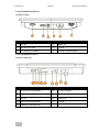
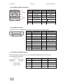
1.4.2 G-WIN Panel PC 15”
Icon
Button
Function
Power
Turn ON or turn OFF the Panel PC.
Reset
Clear any pending errors or events and brings a system
to normal condition or an initial state.
Lock / Unlock
Tap this button to lock / unlock the function of OSD
panel.
Auto Dimming/
Manually
Tap the button once to AUTOMATICALLY adjust
brightness mode.
Press the button again to MANUALLY adjust brightness
mode.
Day/ Night Mode
Tap this button to enter DAY MODE.
Tap this button to enter NIGHT MODE to increase
visibility in low-light conditions.
Brightness UP
Increase the brightness of the display screen, or allows
user to navigate items of a single OSD menu.
Brightness DOWN
Decrease the brightness of the display screen, or allows
user to navigate items of a single OSD menu.
LED Adjustment
Adjust the brightness of the LED.

User Manual Chapter 1 Introduction
18
G-WIN Vehicle Mount Panel PC
LED Indicators
Indicator
Color
Definition
PWR
Green
Power is ON and the device functions normally
Orange
Panel PC is suspended
HDD
Green
HDD is active
OFF
HDD is inactive

G-WIN Vehicle Mount Panel PC
19
Getting Started
This chapter tells you important information on
power supply, adapter and precautions tips. Pay
attention to power considerations.

User Manual Chapter 3 Operating the Device
20
G-WIN Vehicle Mount Panel PC
Chapter 2: Getting Started
This chapter provides information on how to connect the device to the source of power,
connector pinouts and the guideline to turn on/off the Panel PC.
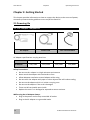
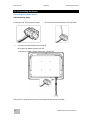
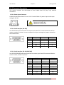
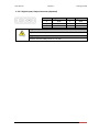
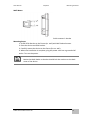
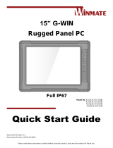
2.1 Powering On
2.1.1 AC Adapter Components
AC Adapter specifications vary by panel size.
Size
8.4”
10.4”
12.1”
15”
AC Adapter
12V/ 50W
12V/ 50W
12V/ 50W
12V/ 80W
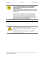
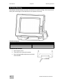
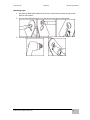
Safety Precautions:
Do not use the adapter in a high moisture environment
Never touch the adapter with wet hands or foot
Allow adequate ventilation around adapter while using
Do not cover the adapter with paper or other objects that will reduce cooling
Do not use the adapter while it is inside a carrying case
Do not use the adapter if the cord is damaged
There are NO serviceable parts inside
Replace the unit if it is damaged or exposed to excess moisture
While using the AC Adapter always:
Plug-in the power cord to easy accessible AC outlet
Plug-in the AC adapter to a grounded outlet
AC Adapter
Power Cord
3 Pin Terminal Block
La page est en cours de chargement...
La page est en cours de chargement...
La page est en cours de chargement...
La page est en cours de chargement...
La page est en cours de chargement...
La page est en cours de chargement...
La page est en cours de chargement...
La page est en cours de chargement...
La page est en cours de chargement...
La page est en cours de chargement...
La page est en cours de chargement...
La page est en cours de chargement...
La page est en cours de chargement...
La page est en cours de chargement...
La page est en cours de chargement...
La page est en cours de chargement...
La page est en cours de chargement...
La page est en cours de chargement...
La page est en cours de chargement...
La page est en cours de chargement...
La page est en cours de chargement...
La page est en cours de chargement...
La page est en cours de chargement...
La page est en cours de chargement...
La page est en cours de chargement...
La page est en cours de chargement...
La page est en cours de chargement...
La page est en cours de chargement...
La page est en cours de chargement...
La page est en cours de chargement...
La page est en cours de chargement...
La page est en cours de chargement...
La page est en cours de chargement...
La page est en cours de chargement...
La page est en cours de chargement...
La page est en cours de chargement...
La page est en cours de chargement...
La page est en cours de chargement...
La page est en cours de chargement...
La page est en cours de chargement...
La page est en cours de chargement...
La page est en cours de chargement...
La page est en cours de chargement...
La page est en cours de chargement...
La page est en cours de chargement...
La page est en cours de chargement...
La page est en cours de chargement...
La page est en cours de chargement...
La page est en cours de chargement...
-
 1
1
-
 2
2
-
 3
3
-
 4
4
-
 5
5
-
 6
6
-
 7
7
-
 8
8
-
 9
9
-
 10
10
-
 11
11
-
 12
12
-
 13
13
-
 14
14
-
 15
15
-
 16
16
-
 17
17
-
 18
18
-
 19
19
-
 20
20
-
 21
21
-
 22
22
-
 23
23
-
 24
24
-
 25
25
-
 26
26
-
 27
27
-
 28
28
-
 29
29
-
 30
30
-
 31
31
-
 32
32
-
 33
33
-
 34
34
-
 35
35
-
 36
36
-
 37
37
-
 38
38
-
 39
39
-
 40
40
-
 41
41
-
 42
42
-
 43
43
-
 44
44
-
 45
45
-
 46
46
-
 47
47
-
 48
48
-
 49
49
-
 50
50
-
 51
51
-
 52
52
-
 53
53
-
 54
54
-
 55
55
-
 56
56
-
 57
57
-
 58
58
-
 59
59
-
 60
60
-
 61
61
-
 62
62
-
 63
63
-
 64
64
-
 65
65
-
 66
66
-
 67
67
-
 68
68
-
 69
69


dans d''autres langues
- English: Winmate G-WIN User manual
Documents connexes
-
 Winmate W12IB3S-VMM9 Guide de démarrage rapide
-
 Winmate R10IB3S-67T2 Quick Start Manuals
-
 Winmate R15ID3S-65A1FTE Guide de démarrage rapide
-
 Winmate W10IB3S-EHH2 Guide de démarrage rapide
-
 Winmate R15IB3S-GSC3 Guide de démarrage rapide
-
 Winmate R12IBWS-MHM2 Manuel utilisateur
-
Winmate R12IHWS-MHM2 Guide de démarrage rapide
-
 Winmate R15IH3S-67A3 Guide de démarrage rapide
-
 Winmate W15IB3S-POA4 Guide de démarrage rapide
-
 Winmate R15IB3S-67A3HB Guide de démarrage rapide