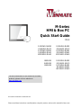
Winmate R12IHWS-MHM2 Guide de démarrage rapide
- Taper
- Guide de démarrage rapide

Please read these instructions carefully before using this product, and save this manual for future use.
Document Part Number: 915211101023
M-Series
HMI & Box PC
Quick Start Guide
V1.1
R12IBWS-MHM2
R15IBWS-MHC3
R17IBWS-MHM1
R19IBWS-MHA1
W22IBWS-MHA3
R12IHWS-MHM2
R15IHWS-MHC3
R17IHWS-MHM1
R19IHWS-MHA1
W22IHWS-MHA3
IBMH100
IHMH100
IKMH100
R12IKWS-MHM2
R15IKWS-MHC3
R17IKWS-MHM1
R19IKWS-MHA1
W22IKWS-MHA3
For more information on this and other Winmate
products, please visit our website at:
www.winmate.com

ii
FCC Statement
This device complies with part 15 FCC rules.
Operation is subject to the following two conditions:
This device may not cause harmful interference.
This device must accept any interference received
including interference that may cause undesired operation.
This equipment has been tested and found to comply with the limits for a
class "B" digital device, pursuant to part 15 of the FCC rules. These limits are
designed to provide reasonable protection against harmful interference when
the equipment is operated in a commercial environment. This equipment
generates, uses, and can radiate radio frequency energy and, if not installed
and used in accordance with the instruction manual, may cause harmful
interference to radio communications. Operation of this equipment in a
residential area is likely to cause harmful interference in which case the user
will be required to correct the interference at him own expense.
European Union
Electromagnetic Compatibility Directive (2014/30/EU)
EN55024: 2010/ A1: 2015
o IEC61000-4-2: 2009
o IEC61000-4-3: 2006+A1: 2007+A2: 2010
o IEC61000-4-4: 2012
o IEC61000-4-5: 2014
o IEC61000-4-6: 2014
o IEC61000-4-8: 2010
o IEC61000-4-11: 2004
EN55032: 2012/AC:2013
EN61000-3-2:2014
EN61000-3-3:2013
Low Voltage Directive (2014/35/EU)
EN 60950-1:2006/A11:2009/A1:2010/A12:2011/ A2:2013
This equipment is in conformity with the requirement of the following EU
legislations and harmonized standards. Product also complies with the
Council directions.

iii
Copyright Notice
No part of this document may be reproduced, copied, translated, or transmitted in
any form or by any means, electronic or mechanical, for any purpose, without the
prior written permission of the original manufacturer.
Trademark Acknowledgement
Brand and product names are trademarks or registered trademarks of their
respective owners.
Disclaimer
Winmate Inc. reserve the right to make changes, without notice, to any product,
including circuits and/or software described or contained in this manual in order
to improve design and/or performance. We assume no responsibility or liability
for the use of the described product(s) conveys no license or title under any
patent, copyright, or masks work rights to these products, and make no
representations or warranties that these products are free from patent, copyright,
or mask work right infringement, unless otherwise specified. Applications that are
described in this manual are for illustration purposes only. We make no
representation or guarantee that such application will be suitable for the specified
use without further testing or modification.
Warranty
Winmate Inc. warranty guarantees that each of its products will be free from
material and workmanship defects for a period of one year from the invoice date.
If the customer discovers a defect, we will, at his/her option, repair or replace the
defective product at no charge to the customer, provide it is returned during the
warranty period of one year, with transportation charges prepaid. The returned
product must be properly packaged in its original packaging to obtain warranty
service. If the serial number and the product shipping data differ by over 30 days,
the in-warranty service will be made according to the shipping date. In the serial
numbers the third and fourth two digits give the year of manufacture, and the fifth
digit means the month (e. g., with A for October, B for November and C for
December).
For example, the serial number 1W16Axxxxxxxx means October of year 2016.

iv
Customer Service
We provide a service guide for any problem by the following steps: First, visit the
website of our distributor to find the update information about the product.
Second, contact with your distributor, sales representative, or our customer
service center for technical support if you need additional assistance.
You may need the following information ready before you call:
Product serial number
Software (OS, version, application software, etc.)
Description of complete problem
The exact wording of any error messages
In addition, free technical support is available from our engineers every business
day. We are always ready to give advice on application requirements or specific
information on the installation and operation of any of our products.
Safety Information
WARNING! / AVERTISSEMENT!
Always completely disconnect the power cord from your chassis
whenever you work with the hardware. Do not make connections
while the power is on. Sensitive electronic components can be
damaged by sudden power surges. Only experienced electronics
personnel should open the PC chassis.
Toujours débrancher le cordon d’alimentation du chassis lorsque
vous travaillez sur celui-ci. Ne pas brancher de connections
lorsque l’alimentation est présente. Des composantes
électroniques sensibles peuvent être endommagées par des sauts
d’alimentation. Seulement du personnel expérimenté devrait ouvrir
ces chassis.
CAUTION/ATTENTION
Always ground yourself to remove any static charge before
touching the CPU card. Modern electronic devices are very
sensitive to static electric charges. As a safety precaution, use a
grounding wrist strap at all times. Place all electronic components
in a static-dissipative surface or static-shielded bag when they are
not in the chassis.
Toujours verifier votre mise à la terre afin d’éliminer toute charge
statique avant de toucher la carte CPU. Les équipements
électroniques moderns sont très sensibles aux décharges
d’électricité statique. Toujours utiliser un bracelet de mise à la
terre comme précaution. Placer toutes les composantes
électroniques sur une surface conçue pour dissiper les charge, ou
dans un sac anti-statique lorsqu’elles ne sont pas dans le chassis.

v
CONTENTS
INTRODUCTION 1
Features 1
Package Contents 2
Product Overview 3
System Introduction 3
Display 4
Box PC 5
GETTING STARTED 9
Turning On Your Device 9
Connecting to AC Power Source 9
Connecting to DC Power Source 10
Turning Off Your Device 11
INSTALLATION 12
Wiring Requirements 12
Mounting 13
Panel Mounting 13
VESA Mounting 15
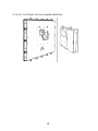
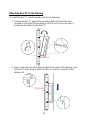
System Modifications 16
Detaching Box PC from Display 16
Attaching Box PC to the Display 19
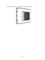
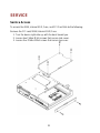
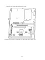
SERVICE 21
Service Access 21
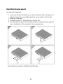
Hard Disk Replacement 23
APPENDIX 24
Appendix A: Cleaning the Monitor 24


1
INTRODUCTION
Congratulations on purchasing Winmate® M-Series HMI. M-Series HMI is
designed to provide versatile and cost-effective solution for your industrial needs.
P-CAP multi-touch screen equipped with industrial motherboard offers various
input/ output connectors. Fanless cooling system and powerful processor
assures steady performance and silent functioning.
M-Series HMI perfectly fits in applications where total costs of ownership (TCO)
and quick recovery of failure is important. The flexible system design provides
easy access to components and can be serviced by local maintenance team.
Versatile, easy-to-service and upgradable M-Series HMI is the best solution for
industrial and building automation.
Features
Winmate® M-Series HMI features:
Signature true flat display screen with edge-to-edge design
Aluminum, anti-corrosion treated housing
Superior Sealing with front IP65 protection against dust and water
Projected Capacitive Multi-Touch (P-CAP)
Fanless cooling system
Modular design
Support wide range DC input with isolation
Quick & Easy Removable 2.5” SSD Bay Slot
NOTE:
Some pictures in this guide are samples and can differ from actual
product

2
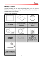
Package Contents
Carefully remove the box and unpack your device. Please check if all the items
listed below are inside your package. If any of these items are missing or
damaged contact us immediately.
Standard factory shipment list:
HMI Device
Quick Start Guide
(Hardcopy)
Driver CD & User
Manual
AC Adapter
(12V/ 80W)
Power Cable
Mounting Clips &
Screws
12.1” HMI – 8 pcs
15” HMI – 12 pcs
17”/ 19” HMI – 14 pcs
21.5” HMI – 16 pcs
3-pin Terminal Block
Female Connector Set

3
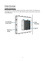
Product Overview
System Introduction
M-Series HMI is a flexible modular system that consists of the Front Display and
detachable Box PC from the rear side. Modular system design allows easy repair
and modifications.

4
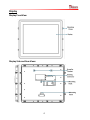
Display
Display Front View
Display Side and Rear Views

5
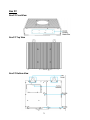
Box PC
Box PC Front View
Box PC Top View
Box PC Bottom View

6
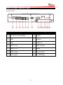
Input and Output Connectors Layout
Intel® Atom™
No
Description
No
Description
①
12-24V DC with isolation
⑧
COM1
②
LAN
⑨
Audio in
③
LAN
⑩
Audio out
④
USB 2.0 x 2
⑪
HDD indicator
⑤
USB 2.0 x 2
⑫
Reset
⑥
HDMI output
⑬
Power Button
⑦
VGA output
⑭
2.4” SSD Bay

7
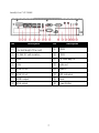
Intel® Core™ i5 5200U
No
Description
No
Description
①
PCIe Slot cover for PCIe x 4
(1 x Half-length PCIe card)
⑨
COM2
②
12-24V DC with isolation
⑩
COM1
③
LAN
⑪
2.5” SSD Bay x 2
④
LAN
⑫
Audio out
⑤
USB 3.0 x 2
⑬
Audio in
⑥
USB 3.0 x 2
⑭
HDD indicators
⑦
HDMI output
⑮
Reset
⑧
VGA output
⑯
Power Button

8
Intel® Core™ i5 6200U
No
Description
No
Description
①
PCIe Slot Cover for one half-
length PCIe x4 card
⑩
Mic in
②
9-29V isolation DC-in
⑪
2.5” HDD x 1
③
Giga LAN
⑫
Expansion slot (Preliminary)*
④
Giga LAN
⑬
Line in
⑤
USB 3.0 x 2
⑭
Line out
⑥
USB 3.0 x 2
⑮
LED indicators
⑦
HDMI output
⑯
Reset
⑧
VGA Output
⑰
Power Button
⑨
COM2
*Expansion slot configurations (Preliminary):
USB 2.0 x 4
Giga LAN x 2
COM x 2
3G with SIM x 1
USB 3.0 x 2

9
GETTING STARTED
Turning On Your Device
The HMI device will automatically turn on when connected to the power source.
Connecting to AC Power Source
To connect the HMI to AC power source:
1. Plug one end of the terminal block cable firmly to the DC Jack.
2. Plug the other end of the terminal block plug to the AC adapter.
3. Connect the AC adapter to the power cord.
4. Plug the power cord to a working AC outlet. The device will boot
automatically.
Note:
Power cords vary in appearance by region and country.

10
Connecting to DC Power Source
To connect the HMI to DC power source:
1. Insert the exposed wires of the DC Power Cable to the appropriate
connectors on the terminal block plug.
2. Plug the terminal block plug firmly to the DC IN Jack.
3. Connect the other end of the DC power cable (wires with lug terminals that
are labeled + and – to the terminals of the DC Power Source. Ensure that
the power connections maintain the proper polarity.

11
Turning Off Your Device
You can Turn OFF the HMI device with the Windows power settings.
To shut down the device:
1. Tap Start >Shut down.
2. Wait for your HMI device to completely turn off before disconnecting the
power cord (if necessary).

12
INSTALLATION
Wiring Requirements
The following common safety precautions should be observed before installing
any electronic device:
Strive to use separate, non-intersecting paths to route power and
networking wires. If power wiring and device wiring paths must cross make
sure the wires are perpendicular at the intersection point.
Keep the wires separated according to interface. The rule of thumb is that
wiring that shares similar electrical characteristics may be bundled together.
Do not bundle input wiring with output wiring. Keep them separate.
When necessary, it is strongly advised that you label wiring to all devices in
the system.
CAUTION
Do not run signal or communication wiring and power wiring in the same
conduit. To avoid interference, wires with different signal characteristics
(i.e., different interfaces) should be routed separately.
Be sure to disconnect the power cord before installing and/or wiring your
device.
Verify the maximum possible current for each wire gauge, especially for the
power cords. Observe all electrical codes dictating the maximum current
allowable for each wire gauge.
If the current goes above the maximum ratings, the wiring could overheat,
causing serious damage to your equipment.
Be careful when handling the unit. When the unit is plugged in, the internal
components generate a lot of heat which may leave the outer casing too
hot to touch.

13
Mounting
M-series HMI devices come with different mounting options suitable for most of
the industrial and commercial applications.
Panel Mounting
Panel mounting solution allows installing the HMI device onto the wall or
instrument panel. M-Series comes with the mounting clamps and screws for fast
and easy mounting.
Cutout dimensions and mounting kit:
Cutout dimension ( W x D in mm)
12.1”
15”
17”
19”
21.5”
301 x 237
342 x 261
373 x 311
412 x 338
504 x 304
Mounting Clips
8 pcs
12 pcs
12 pcs
14 pcs
16 pcs
Screws
Short screws: 15mm M4
Long screws: 30mm M4

14
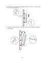
To mount the device to a sub frame or panel, do the following:
NOTE:
Use either short (15mm) or long (30mm) screws based on the
thickness of the wall.
La page est en cours de chargement...
La page est en cours de chargement...
La page est en cours de chargement...
La page est en cours de chargement...
La page est en cours de chargement...
La page est en cours de chargement...
La page est en cours de chargement...
La page est en cours de chargement...
La page est en cours de chargement...
La page est en cours de chargement...
La page est en cours de chargement...
La page est en cours de chargement...
La page est en cours de chargement...
-
 1
1
-
 2
2
-
 3
3
-
 4
4
-
 5
5
-
 6
6
-
 7
7
-
 8
8
-
 9
9
-
 10
10
-
 11
11
-
 12
12
-
 13
13
-
 14
14
-
 15
15
-
 16
16
-
 17
17
-
 18
18
-
 19
19
-
 20
20
-
 21
21
-
 22
22
-
 23
23
-
 24
24
-
 25
25
-
 26
26
-
 27
27
-
 28
28
-
 29
29
-
 30
30
-
 31
31
-
 32
32
-
 33
33


Winmate R12IHWS-MHM2 Guide de démarrage rapide
- Taper
- Guide de démarrage rapide
dans d''autres langues
Documents connexes
-
 Winmate W10IB3S-PCH2AC-PoE S-Series Guide de démarrage rapide
-
 Winmate W10IB3S-EHH2 Guide de démarrage rapide
-
 Winmate W07IB3S-PCM1 Guide de démarrage rapide
-
 Winmate W15FA3S-EHA2 Guide de démarrage rapide
-
 Winmate W15FA3S-EHA2 Guide de démarrage rapide
-
 Winmate W15FA3S-EHA2 Guide de démarrage rapide
-
 Winmate R15FA3S-PCC3-PoE Guide de démarrage rapide
-
 Winmate W07FA3S-PCM1-PoE Manuel utilisateur
-
 Winmate W15FA3S-EHA2 Manuel utilisateur
-
 Winmate G-WIN Manuel utilisateur


