GE GTH21SCWSS Manuel utilisateur
- Catégorie
- Frigos
- Taper
- Manuel utilisateur

ge.com
Refrigerators
Top-Freezer
197D7733P001 49-60505-1 07-07 JR
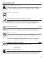
Safety Instructions . . . . . . . . . . .2–4
Operating Instructions
Automatic Icemaker . . . . . . . . . . . .9
Controls . . . . . . . . . . . . . . . . . . . . . .5
Crispers and Pans . . . . . . . . . . . .7, 8
Shelves and Bins . . . . . . . . . . . . . . .6
Care and Cleaning
Care and Cleaning . . . . . . . . . .10, 11
Replacing the Light Bulb . . . . . . .11
Installation Instructions
Icemaker Installation . . . . . . . .13–16
Preparing to Install
the Refrigerator . . . . . . . . . . . . . . .12
Reversing the Door Swing . . . .21–25
Water Line Installation . . . . . .17–21
Troubleshooting Tips . . . . . . .26–29
Normal Operating Sounds . . . . . .26
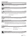
Consumer Support
Consumer Support . . . . .Back Cover
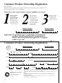
Product Registration
for Canadian Customers . . . . .33, 34
Product Registration
for U.S. Customers . . . . . . . . .31, 32
Warranty for
Canadian Customers . . . . . . . . . . .35
Warranty for U.S. Customers . . . . .36
Réfrigérateurs
Congélateur supérieur
Refrigeradores
Congelador superior
Models GTH21 and GTL21
Manuel d’utilisation
et d’installation
Owner’s Manual and
Installation Instructions
Manual del propietario
e instalación
La section française commence à la page 37
La sección en español empieza en la página 73
Note to Installer – Be sure to leave
these instructions with the Consumer.
Note to Consumer – Keep these
instructions for future reference.
Note à l’installateur – Assurez-vous
de laisser ces instructions au
consommateur.
Note au consommateur –
Conservez ces instructions pour
référence future.
Nota al instalador – Asegúrese
de dejar estas instrucciones con el
consumidor.
Nota al consumidor – Conserve
estas instrucciones para referencia futura.
Write the model and serial numbers here:
Model # __________________________
Serial # __________________________
Find these numbers on the gray label
on the left side, near the top of the
refrigerator compartment.

IMPORTANT SAFETY INFORMATION.
READ ALL INSTRUCTIONS BEFORE USING.
WARNING!
Use this appliance only for its intended purpose as described in this Owner’s Manual.
SAFETY PRECAUTIONS
When using electrical appliances, basic safety precautions should be followed, including the following:
■
■ This refrigerator must be properly installed
and located in accordance with the Installation
Instructions before it is used.
■
■ Do not allow children to climb, stand or hang
on the shelves in the refrigerator. They could
damage the refrigerator and seriously injure
themselves.
■
■ Do not touch the cold surfaces in the freezer
compartment when hands are damp or wet.
Skin may stick to these extremely cold surfaces.
■
■ Do not store or use gasoline or other flammable
vapors and liquids in the vicinity of this or any
other appliance.
■
■ In refrigerators with automatic icemakers,
avoid contact with the moving parts of the
ejector mechanism, or with the heating element
located on the bottom of the icemaker. Do not
place fingers or hands on the automatic
icemaking mechanism while the refrigerator
is plugged in.
■
■ Keep fingers out of the “pinch point” areas;
clearances between the doors and between the
doors and cabinet are necessarily small. Be careful
closing doors when children are in the area.
■
■ Unplug the refrigerator before cleaning and
making repairs.
NOTE: We strongly recommend that any servicing be
performed by a qualified individual.
■
■ Setting either or both controls (some models only
have one control) to the 1 (off) position does not
remove power to the light circuit.
■
■ Do not refreeze frozen foods which have
thawed completely.
Consumer Support Troubleshooting Tips
Operating Instructions Safety InstructionsInstallation Instructions
2

3
Consumer SupportTroubleshooting TipsOperating InstructionsSafety Instructions Installation Instructions
ge.com
USE OF EXTENSION CORDS
Because of potential safety hazards under certain conditions, we strongly recommend against the
use of an extension cord.
However, if you must use an extension cord, it is absolutely necessary that it be a UL-listed (in the United
States) or a CSA-listed (in Canada), 3-wire grounding type appliance extension cord having a grounding
type plug and outlet and that the electrical rating of the cord be 15 amperes (minimum) and 120 volts.
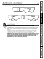
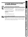
DANGER! RISK OF CHILD ENTRAPMENT
PROPER DISPOSAL OF THE REFRIGERATOR
Child entrapment and suffocation are not
problems of the past. Junked or abandoned
refrigerators are still dangerous…even if they will
sit for “just a few days.” If you are getting rid of
your old refrigerator, please follow the instructions
below to help prevent accidents.
Before You Throw Away Your Old
Refrigerator or Freezer:
■ Take off the doors.
■ Leave the shelves in place so that children
may not easily climb inside.
Refrigerants
All refrigeration products contain refrigerants,
which under federal law must be removed prior
to product disposal. If you are getting rid of an
old refrigeration product, check with the company
handling the disposal about what to do.

4
Consumer Support Troubleshooting Tips
Operating Instructions Safety InstructionsInstallation Instructions
IMPORTANT SAFETY INFORMATION.
READ ALL INSTRUCTIONS BEFORE USING.
WARNING!
HOW TO CONNECT ELECTRICITY
Do not, under any circumstances, cut or remove the third (ground) prong from the power cord.
For personal safety, this appliance must be properly grounded.
The power cord of this appliance is equipped with
a 3-prong (grounding) plug which mates with a
standard 3-prong (grounding) wall outlet to
minimize the possibility of electric shock hazard
from this appliance.
Have the wall outlet and circuit checked by a
qualified electrician to make sure the outlet is
properly grounded.
Where a standard 2-prong wall outlet is
encountered, it is your personal responsibility and
obligation to have it replaced with a properly
grounded 3-prong wall outlet.
The refrigerator should always be plugged into its
own individual electrical outlet which has a voltage
rating that matches the rating plate.
This provides the best performance and also
prevents overloading house wiring circuits which
could cause a fire hazard from overheated wires.
Never unplug your refrigerator by pulling on the
power cord. Always grip plug firmly and pull
straight out from the outlet.
Repair or replace immediately all power cords that
have become frayed or otherwise damaged. Do not
use a cord that shows cracks or abrasion damage
along its length or at either end.
When moving the refrigerator away from the
wall, be careful not to roll over or damage the
power cord.
READ AND FOLLOW THIS SAFETY INFORMATION CAREFULLY.
SAVE THESE INSTRUCTIONS

Consumer SupportTroubleshooting TipsOperating Instructions
Safety Instructions
Installation Instructions
5
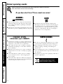
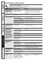
About the controls on the refrigerator. ge.com
Control Settings
Initially, set the control(s) at 4. Allow 24 hours for the temperature to stabilize.
Several adjustments may be required. Adjust the control(s) one increment at a time and
allow 12 hours after each adjustment for the refrigerator to reach the temperature you
have set.
Setting the refrigerator control to 1 stops cooling in both the freezer and refrigerator
compartments but does not shut off electrical power to the refrigerator. The freezer
control (on some models) has no effect on electrical power to the refrigerator.
Control settings will vary based on personal preferences, usage and operating conditions,
and may require more than one adjustment. Factors that affect temperature include the
amount of food in the refrigerator or freezer, the frequency of door opening and the
temperature of food when it is placed in the refrigerator.
4
The controls on your refrigerator will look like one of the following:
44

6
Consumer Support Troubleshooting Tips
Operating Instructions Safety InstructionsInstallation Instructions
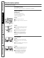
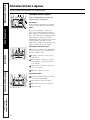
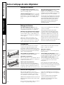
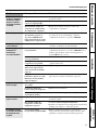
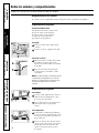
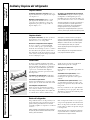
About the shelves and bins.
Not all features are on all models.
Rearranging the Shelves
Shelves in the refrigerator and freezer compartments are adjustable.
Refrigerator Compartment
Half-Width Shelves
One end of the shelf rests on a
molded side-wall support; a bracket
on the other end hooks into a track
on the rear cabinet wall.
To remove:
Tilt the shelf up at the front.
Lift the support off and out of the track.
To replace:
While tilting the shelf up, insert the top
hook at the back of the shelf in a slot
on the track.
Lower the front of the shelf until the
bottom of the shelf locks into place.
NOTE: The shelf to the right of the track is
designed to hook into the right-hand slot; the
shelf to the left is designed to hook into the
left-hand slot.
Freezer Compartment
To remove:
Lift up the left side of the shelf and
slide it left into the center of the shelf
supports.
Rotate the right side of the shelf up and
out of the shelf supports.
To replace:
Holding the shelf diagonally, insert the
left end of the shelf into the center of
the shelf supports on the side wall.
Insert the right end of the shelf into
the shelf supports on the side wall.
Rest each end of the shelf on the
bottom of the shelf supports.
Lift up
and out
Tilt up

7
Consumer SupportTroubleshooting TipsOperating Instructions
Safety Instructions
Installation Instructions
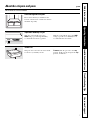
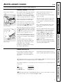
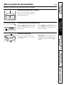
Adjustable Humidity Crisper
Slide the control all the way to the
HIGH setting to provide high humidity
recommended for most vegetables.
Slide the control all the way to the LOW
setting to provide lower humidity levels
recommended for most fruits.
Snack Pan
This pan can be moved to the most useful
location for your family’s needs.
To remove, slide the pan out to the stop
position, lift the pan up and past the stop
position, and lift out.
About the crispers and pans. ge.com
Not all features are on all models.
Fruit and Vegetable Crispers
Excess water that may accumulate in the
bottom of the drawers or under the drawers
should be wiped dry.

8
Consumer Support Troubleshooting Tips
Operating Instructions Safety InstructionsInstallation Instructions
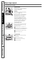
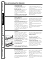
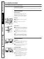
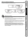
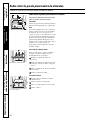
Removing the glass cover
Removing the frame
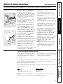
About crisper removal.
Not all features are on all models.
Crisper Removal
Unload the bottom shelf before attempting to
remove the storage drawers.
To Remove:
Lift the drawers up slightly while pulling
them past the stop location.
If the door prevents you from taking out
the drawers, first try to remove the door
bins. If this does not offer enough
clearance, the refrigerator will need to
be rolled forward until the door opens
enough to slide the drawers out. In some
cases, when you roll the refrigerator out,
you will need to move the refrigerator
to the left or right as you roll it out.
To remove the glass cover:
Remove the glass, then the frame. When
replacing the glass, push the front edge
firmly into the frame.
Push up the glass cover at the rear.
Slide the glass cover backwards until the
front edge comes out of the frame.
Rotate the side of the glass cover up.
Remove the glass cover.
To remove the frame:
Lift up the front of the frame using
both hands.
Slide the frame forward.
Rotate the side of the frame up.
Remove the frame.

Consumer SupportTroubleshooting TipsOperating InstructionsSafety Instructions Installation Instructions
9
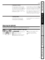
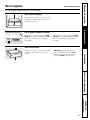
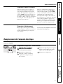
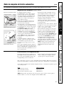
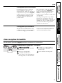
Icemaker
Feeler Arm
Power
Switch
Green
Power Light
Feeler Arm in
the STOP
(up) position
Feeler Arm in
the ON (down)
position
Feeler arm model
Power switch model
There are 2 types of icemakers:
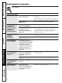
About the automatic icemaker. ge.com
A newly-installed refrigerator may take 12–24 hours to begin making ice.
Automatic Icemaker (on some models)
The icemaker will produce approximately
3 to 3
1
⁄2 lbs. of ice in a 24-hour period,
depending on the freezer compartment
temperature, room temperature, number
of door openings and other use conditions.
There are two types of icemakers: power
switch models and feeler arm models.
If the refrigerator is operated before the
water connection is made to the icemaker,
set the power switch to O (off) or move the
feeler arm to the STOP (up) position.
When the refrigerator has been connected
to the water supply, set the power switch to
the I (on) position or move the feeler arm to
the ON (down) position. On power switch
models, the green light will come on.
The icemaker will fill with water when it
cools to 15°F. A newly-installed refrigerator
may take 12 to 24 hours to begin making
ice cubes.
Once the icemaker starts to make ice,
it may take up to 48 hours to fill the bin,
depending on the temperature settings
and number of door openings.
You will hear a buzzing sound each time
the icemaker fills with water.
Throw away the first few batches of ice
to allow the water line to clear.
Be sure nothing interferes with the sweep
of the feeler arm.
When the bin fills to the level of the feeler
arm, the icemaker will stop producing ice.
It is normal for several cubes to be joined
together.
If ice is not used frequently, old ice cubes
will become cloudy, taste stale, shrink or
fuse together.
On power switch models, the green power
light will blink if ice cubes get stuck in the
icemaker. To correct this, set the power
switch to O (off) and remove the cubes.
Set the power switch to I (on) to restart the
icemaker. After the icemaker has been
turned on again, there will be a delay of
about 45 minutes before the icemaker
resumes operation.
NOTE: In homes with lower-than-average water
pressure, you may hear the icemaker cycle multiple
times when making one batch of ice.
Icemaker Accessory Kit
If your refrigerator did not already come
equipped with an automatic icemaker,
an icemaker accessory kit is available at
extra cost.
Check the back of the refrigerator for the
specific icemaker kit needed for your model.
This refrigerator will accept accessory icemaker IM4A or IM6. Use instruction sheet L
supplied in the kit for assembly inside freezer compartment.
To facilitate installation of an icemaker kit, the following parts are included with your
refrigerator:
Part Part Number
Ice Fill Cup WR29X10074
Ice Fill Tube WR17X12339
Ice Fill Tube Seal WR17X12337
NOTE: It is important that you DO NOT discard these parts, as they will be needed if
you plan to install accessory icemaker kit IM4A or IM6.

10
Consumer Support Troubleshooting Tips
Operating Instructions Safety InstructionsInstallation Instructions
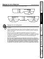
Care and cleaning of the refrigerator.
Cleaning the Outside
The door handles and trim. Clean with
a cloth dampened with soapy water.
Dry with a soft cloth.
Keep the outside clean. Wipe with a clean
cloth lightly dampened with kitchen
appliance wax or mild liquid dish
detergent. Dry and polish with a clean,
soft cloth.
The stainless steel panels and door handles
(on some models) can be cleaned with
a commercially available stainless steel
cleaner. Do not use appliance wax or polish
on the stainless steel.
Do not wipe the refrigerator with a soiled dish cloth
or wet towel. These may leave a residue that
can erode the paint. Do not use scouring pads,
powdered cleaners, bleach or cleaners containing
bleach because these products can scratch and
weaken the paint finish.
Cleaning the Inside
To help prevent odors, leave an open box of
baking soda in the fresh food and freezer
compartments.
Unplug the refrigerator before cleaning. If this
is not practical, wring excess moisture out
of sponge or cloth when cleaning around
switches, lights or controls.
Use warm water and baking soda solution—
about a tablespoon (15 ml) of baking soda
to a quart (1 liter) of water. This both cleans
and neutralizes odors. Thoroughly rinse
and wipe dry.
Avoid cleaning cold glass shelves (on some models)
with hot water because the extreme temperature
difference may cause them to break. Handle glass
shelves carefully. Bumping tempered glass can cause
it to shatter.
Do not wash any plastic refrigerator parts in the
dishwasher.
Do not clean with any products containing detergent,
bleach or ammonia. They may damage the
refrigerator.
Condenser
There is no need for routine condenser
cleanings in normal home operating
environments. However, in environments
that may be particularly dusty or greasy, the
condenser should be cleaned periodically
for efficient refrigerator operation.
For models with a base grille, the grille must
be removed in order to clean the condenser.
To remove the base grille:
Grasp it about 6″ from each end and pull
its bottom edge toward you.
To replace the base grille:
Insert the tops of the metal clips into the
oval vents, making sure one of the plastic
tabs on the back of the grille goes into each
of the oval vents. Then push the bottom of
the grille forward until it snaps into place.
Cleaning the condenser:
Sweep away or vacuum up dust.
For models with a base grille, reach the
condenser by inserting a brush or vacuum
hose into the oval holes.
For models without a base grille, reach the
condenser by inserting a brush or vacuum
hose under the bottom of the refrigerator.
For best results, use a brush specially
designed for this purpose. It is available
at most appliance parts stores.
Behind the Refrigerator
Be careful when moving the refrigerator
away from the wall. All types of floor
coverings can be damaged, particularly
cushioned coverings and those with
embossed surfaces.
BEFORE moving the refrigerator away from the wall,
be sure to adjust the leveling legs up. (See Rollers
and Leveling Legs.)
Pull the refrigerator straight out and return
it to position by pushing it straight in.
Moving the refrigerator in a side direction
may result in damage to the floor covering
or refrigerator.
When pushing the refrigerator back, make sure you
don’t roll over the power cord or icemaker supply line
(on some models).

11
ge.com
Preparing for Vacation
For long vacations or absences, remove
food and unplug the refrigerator. Move
the refrigerator control to the 1 (off) position
and clean the interior with a baking soda
solution of one tablespoon (15 ml) of
baking soda to one quart (1 liter) of water.
Leave the doors open.
Set the icemaker power switch to the O (off)
position or move the feeler arm to the STOP
(up) position (depending on model) and
shut off the water supply to the refrigerator.
If the temperature can drop below freezing,
have a qualified servicer drain the water
supply system (on some models) to prevent
serious property damage due to flooding.
Preparing to Move
Secure all loose items such as grille,
shelves and drawers by taping them
securely in place to prevent damage.
Be sure the refrigerator stays in an upright position
during moving.
Replacing the light bulb.
Setting either or both controls to 1 (off) does not remove power to the light circuit.
Refrigerator Compartment—Upper Light
CAUTION: Light bulb may be hot.
Unplug the refrigerator.
The bulb is located at the top of the
compartment near the opening.
Replace with an appliance bulb of
the same or lower wattage.
Plug the refrigerator back in.
Consumer SupportTroubleshooting TipsOperating Instructions
Safety Instructions
Installation Instructions

12
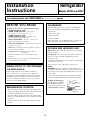
BEFORE YOU BEGIN
Read these instructions completely and carefully.
•
IMPORTANT – Save these
instructions for local inspector’s use.
•
IMPORTANT – Observe all
governing codes and ordinances.
• Note to Installer – Be sure to leave these
instructions with the Consumer.
• Note to Consumer – Keep these instructions
for future reference.
• Skill level – Installation of this appliance requires
basic mechanical skills.
• Completion time – Refrigerator Installation
15 minutes.
• Proper installation is the responsibility of the
installer.
• Product failure due to improper installation is not
covered under the Warranty.
• Do not install the refrigerator where the temperature
will go below 60°F (16°C) because it will not run often
enough to maintain proper temperatures.
• Do not install the refrigerator where the temperature
will go above 100°F (37°C) because it will not perform
properly.
• Install it on a floor strong enough to support it fully
loaded.
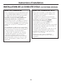
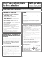
REFRIGERATOR LOCATION
If you have questions, call 1.800.GE.CARES or visit our Website at: ge.com
Installation
Refrigerator
Instructions
Models GTH21 and GTL21
Allow the following clearances for ease of installation,
proper air circulation and plumbing and electrical
connections.
• Sides 1/8″ (3 mm)
• Top 1″ (25 mm)
• Back 1″ (25 mm)
If the refrigerator is to be installed next to a wall on the
hinge side, allow 5/16″ (8 mm) door clearance.
CLEARANCES
If the refrigerator has an icemaker, it will have
to be connected to a cold water line. A GE water
supply kit (containing tubing, shutoff valve, fittings
and instructions) is available at extra cost from your
dealer or by visiting our Website at ge.com or Parts
and Accessories, 800.626.2002.
WATER SUPPLY TO THE ICEMAKER
(ON SOME MODELS)
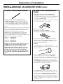
Rollers allow you to move the refrigerator away from the
wall for cleaning.
Leveling Legs near each front corner of the refrigerator,
next to the rollers, should be adjusted if any of the
following occurs:
• Refrigerator wobbles due to front roller not being firmly
positioned on the floor.
• Door(s) do not close easily when opened to 45°.
NOTE:
• BEFORE moving the refrigerator away from the wall,
be sure to turn the leveling legs counterclockwise so that
the weight of the refrigerator is fully transferred to the
front rollers.
• The refrigerator will not be level from front to back. It
will have a slight backward tilt for proper door-closing.
To adjust the leveling legs,
turn the two front leveling
legs clockwise to raise the
front of the refrigerator and
counterclockwise to lower it.
ROLLERS AND LEVELING LEGS
Clockwise to raise
refrigerator

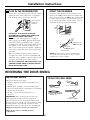
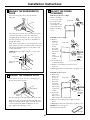
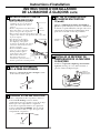
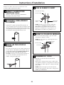
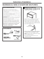
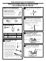
PREPARE FOR INSTALLATION
Inside the freezer, loosen the two mounting screws,
but do not screw them all the way out. If your model
does not have the screws already in the freezer wall,
look for two plug buttons. Remove the plug buttons
and insert the two Phillips head screws. The screws
should extend approximately 1/2″ (13mm) out
from the freezer wall.
3
BEFORE YOU BEGIN
Read each step thoroughly before proceeding.
•
CAUTION – Unplug the
Refrigerator. To eliminate the danger
of electric shock during installation,
you must unplug the refrigerator from
its electrical outlet.
Flat blade and Phillips
screwdrivers
Pliers
TOOLS YOU WILL NEED
REMOVE THE OUTLET COVER
• Remove the outlet cover
with a flat-blade screwdriver.
2
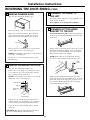
SET POWER SWITCH TO O (off)
Set the icemaker power switch to O (off). Leave
the power switch in the O (off) position until the
refrigerator is connected to the water supply to
prevent premature operation.
4
Power
Switch
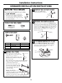
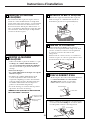
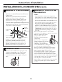
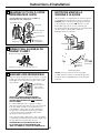
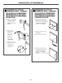
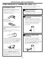
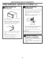
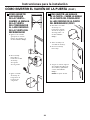
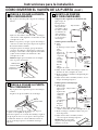
INSTALL FILL TUBE
• If the refrigerator already has a
water tube inlet on the back of the
refrigerator, go to Step 2.
• Remove and discard the white plug
from the lower left back corner of
the freezer wall.
• Go to the back of the refrigerator. Find the small
label in the upper right hand corner and peel it
off. Then discard the label.
• Peel one side of the paper away
from the water fill tube seal, slide
the seal along the tube and affix
to the back side of the water
tube inlet flange.
• Remove the adhesive
backing on the opposite side
of the water fill tube seal and
slide the tube into the hole
near the top at the back of the refrigerator. Firmly
press on the inlet to secure it to the refrigerator.
1
Hole for
wire tie
Remove
plug
(Appearance may vary)
13
Side
Back
Seal
Mounting
screws
Installation Instructions
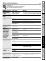
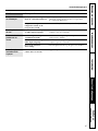
PARTS INCLUDED
1
3
2
NO. DESCRIPTION QUANTITY
1 Water Fill Tube 1
2 Ice Fill Guide 1
3 Water Fill Tube Seal 1
ICEMAKER INSTALLATION INSTRUCTIONS

14
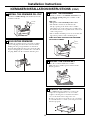
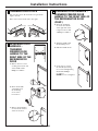
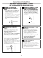
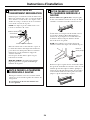
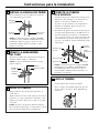
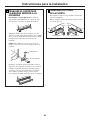
7
PLUG IN THE ICEMAKER
Holding the icemaker in place, insert the icemaker
power cord plug into the socket on the back wall,
making sure the prongs and holes are matched.
Press the plug firmly into the socket. Lock the plug
in place by clipping the restraints onto each side of
the plug. Make sure the restraints click into place.
6
INSTALL THE ICE BUCKET
Place the ice bucket under the icemaker.
Make sure the icemaker power switch is in the
O (off) position.
8
INSTALL THE ICEMAKER FILL CUP
Install the icemaker fill cup (side-mounted) into the
icemaker as shown.
5
MOUNT THE ICEMAKER
• Lift the icemaker so the fill tube extension fits in
the fill cup opening. Hang the icemaker on the
two screws.
Make sure:
• The power cord is still firmly in the socket.
• The fill tube extension extends into the
fill cup opening at the back of the icemaker.
(Check the rear of the refrigerator to make sure
the fill tube has not been pushed out of the back
of the refrigerator).
• The icemaker mounting screws are located in the
uppermost position of the mounting slots.
THEN SECURELY TIGHTEN THE ICEMAKER
MOUNTING SCREWS.
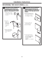
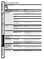
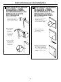
Installation Instructions
REMOVE THE COVER
Use a Phillips head screwdriver to remove the
compressor compartment access cover. This
requires removing six screws which attach the
cover to the back of the refrigerator case.
Be sure to save the screws as the access cover must
be reinstalled later to ensure your refrigerator will
function properly.
9
Icemaker
fill cup
Fill tube
extension
Fill cup
opening
Ice bucket
ICEMAKER INSTALLATION INSTRUCTIONS (CONT.)

15
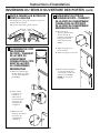
Installation Instructions
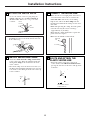
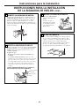
ATTACH THE WATER VALVE
• Locate the female connector plug. Plug the
female connector onto the male terminals on
the water valve. Either wire can go on either
terminal.
10
• Fasten the water valve to the cabinet by driving
the Phillips head screw from the kit into the hole
in the cabinet leg.
Female
connector
Male
terminals
Phillips head
screw
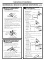
12
CONNECT THE WATER LINE
• Make sure there is enough plastic water line to
extend from the water valve to well into the
water tube inlet. Cut off any excess tubing.
• Squeeze the ends of the hose clamp from the
kit with pliers and slide the clamp over the water
tube inlet.
• While still squeezing the clamp, insert the plastic
water line into the inlet as far as it will go
(approximately 1″ [25 mm]).
• Then slide the clamp downward to capture the
plastic water line in place.
• Make sure the fill tube is aimed down.
Water tube
inlet
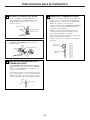
INSTALL WATER LINE CLAMP
• Attach the metal water line clamp (strain relief)
to the refrigerator. Drive the screw from the kit
through the clamp at the indent into the back
of the cabinet.
• The metal clamp is for the house water line (see
the Water Line Installation Instructions). It is not
to be used for the tubing from the water valve up
to the icemaker.
11
Screw
Strain
relief
Hose clamp
ROUTE AND ATTACH THE
PLASTIC WATER LINE
• Fasten the plastic water line to the back
of the cabinet with adhesive-backed fasteners,
spacing the fasteners as shown to take up slack
in the line.
13
Adhesive-backed fasteners
for plastic water line

16
Installation Instructions
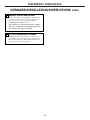
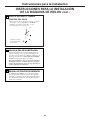
15
ATTACH WARRANTY LABEL
A label is provided with this kit to record the date
of installation for warranty purposes. Apply it to the
back of the refrigerator. The icemaker installation
inside the freezer is now complete.
WATER VALVE INSTALLED
Refer to the Water Line Installation Instructions
for connection to the home water supply. After
water line installation is completed, set the
icemaker power switch to I (on).
The icemaking cycle will not begin until the icemaker
and freezer compartment reach operating temperature,
then icemaking will begin automatically.
14
ICEMAKER INSTALLATION INSTRUCTIONS (CONT.)

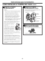
17
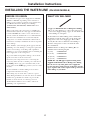
INSTALLING THE WATER LINE
(ON SOME MODELS)
Recommended copper water supply kits are WX8X2,
WX8X3 or WX8X4, depending on the amount of
tubing you need. Approved plastic water supply lines
are GE SmartConnect
™
Refrigerator Tubing
(WX08X10002, WX08X10006, WX08X10015 and
WX08X10025).
When connecting your refrigerator to a GE Reverse
Osmosis Water System, the only approved installation
is with a GE RVKit. For other reverse osmosis water
systems, follow the manufacturer’s recommendations.
This water line installation is not warranted by the
refrigerator or icemaker manufacturer. Follow these
instructions carefully to minimize the risk of expensive
water damage.
Water hammer (water banging in the pipes) in house
plumbing can cause damage to refrigerator parts and
lead to water leakage or flooding. Call a qualified
plumber to correct water hammer before installing the
water supply line to the refrigerator.
To prevent burns and product damage, do not hook
up the water line to the hot water line.
If you use your refrigerator before connecting the
water line, make sure the icemaker power switch is in
the O (off) position (on power switch models) or the
feeler arm is in the STOP (up) position (on feeler arm
models).
Do not install the icemaker tubing in areas where
temperatures fall below freezing.
When using any electrical device (such as a power
drill) during installation, be sure the device is double
insulated or grounded in a manner to prevent the
hazard of electric shock, or is battery powered.
All installations must be in accordance with local
plumbing code requirements.
BEFORE YOU BEGIN
Installation Instructions
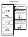
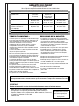
WHAT YOU WILL NEED
• Copper or GE SmartConnect
™
Refrigerator Tubing
kit, 1/4″ outer diameter to connect the refrigerator
to the water supply. If using copper, be sure both ends
of the tubing are cut square.
To determine how much tubing you need: Measure
the distance from the water valve on the back of the
refrigerator to the water supply pipe. Then add 8′
(2.4 m). Be sure there is sufficient extra tubing to
allow the refrigerator to move out from the wall
after installation.
GE SmartConnect
™
Refrigerator Tubing Kits are
available in the following lengths:
2′ (.6 m) – WX08X10002
6′ (1.8 m) – WX08X10006
15′ (4.6 m) – WX08X10015
25′ (7.6 m) – WX08X10025
NOTE: The only GE approved plastic tubing is that
supplied in GE SmartConnect
™
Refrigerator Tubing
kits. Do not use any other plastic water supply line
because the line is under pressure at all times. Certain
types of plastic will crack or rupture with age and cause
water damage to your home.

18
INSTALLING THE WATER LINE (CONT.)
• A GE water supply kit (containing tubing, shutoff
valve and fittings listed below) is available at extra
cost from your dealer or from Parts and Accessories,
800.626.2002.
• A cold water supply. The water pressure must be
between 20 and 120 p.s.i. (1.4–8.1 bar).
• Power drill.
• 1/2″ or adjustable wrench.
• Straight and Phillips blade screwdriver.
• Two 1/4 ″ outer diameter compression nuts and
2 ferrules (sleeves)—to connect the copper tubing to
the shutoff valve and the refrigerator water valve.
OR
• If you are using a GE SmartConnect
™
Refrigerator
Tubing kit, the necessary fittings are preassembled to
the tubing.
• If your existing copper water line has a flared fitting
at the end, you will need an adapter (available at
plumbing supply stores) to connect the water line to
the refrigerator OR you can cut off the flared fitting
with a tube cutter and then use a compression fitting.
Do not cut formed end from GE SmartConnect
™
Refrigerator tubing.
• Shutoff valve to connect to the cold water line.
The shutoff valve should have a water inlet with a
minimum inside diameter of 5/32″ at the point of
connection to the COLD WATER LINE. Saddle-type
shutoff valves are included in many water supply kits.
Before purchasing, make sure a saddle-type valve
complies with your local plumbing codes.
WHAT YOU WILL NEED (CONT.)
Installation Instructions
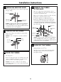
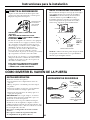
SHUT OFF THE MAIN WATER
SUPPLY
Turn on the nearest faucet long enough to clear
the line of water.
Install the shutoff valve on the nearest frequently used
drinking water line.
1
Choose a location for the valve that is easily
accessible. It is best to connect into the side of a
vertical water pipe. When it is necessary to connect
into a horizontal water pipe, make the connection
to the top or side, rather than at the bottom, to
avoid drawing off any sediment from the water pipe.
CHOOSE THE VALVE LOCATION
2
Drill a 1/4″ hole in the water pipe (even if using a
self-piercing valve), using a sharp bit. Remove any
burrs resulting from drilling the hole in the pipe.
Take care not to allow water to drain into the drill.
Failure to drill a 1/4″ hole may result in reduced
ice production or smaller cubes.
DRILL THE HOLE FOR THE VALVE
3

19
Place the compression nut and ferrule (sleeve)
for copper tubing onto the end of the tubing and
connect it to the shutoff valve.
Make sure the tubing is fully inserted into the valve.
Tighten the compression nut securely.
For plastic tubing from a GE SmartConnect
™
Refrigerator Tubing kit, insert the molded end
of the tubing into the shutoff valve and tighten
compression nut until it is hand-tight; then tighten
one additional turn with a wrench. Overtightening
may cause leaks.
NOTE: Commonwealth of Massachusetts Plumbing
Codes 248CMR shall be adhered to. Saddle valves
are illegal and use is not permitted in Massachusetts.
Consult with your licensed plumber.
CONNECT THE TUBING
TO THE VALVE
7
Turn the main water supply on and flush out the
tubing until the water is clear.
Shut the water off at the water valve after about
one quart (1 liter) of water has been flushed
through the tubing.
FLUSH OUT THE TUBING
8
Installation Instructions
Saddle-Type
Shutoff Valve
Compression
Nut
SmartConnect
™
Tubing
Packing Nut
Outlet Valve
Ferrule (sleeve)
Fasten the shutoff valve to the cold water pipe with
the pipe clamp.
NOTE: Commonwealth of Massachusetts Plumbing
Codes 248CMR shall be adhered to. Saddle valves
are illegal and use is not permitted in Massachusetts.
Consult with your licensed plumber.
FASTEN THE SHUTOFF VALVE
4
Tighten the clamp screws until the sealing washer
begins to swell.
NOTE: Do not overtighten or you may crush the
tubing.
TIGHTEN THE PIPE CLAMP
5
Route the tubing between the cold water line and
the refrigerator.
Route the tubing through a hole drilled in the wall
or floor (behind the refrigerator or adjacent base
cabinet) as close to the wall as possible.
NOTE: Be sure there is sufficient extra tubing
to allow the refrigerator to move out from the wall
after installation.
ROUTE THE TUBING
6
Washer
Inlet End
Pipe Clamp
Clamp Screw
Vertical Cold
Water Pipe
Saddle-Type
Shutoff Valve
Pipe Clamp

20
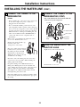
NOTES:
• Before making the connection to the refrigerator,
be sure the refrigerator power cord is not
plugged into the wall outlet.
• We recommend installing a water filter if your
water supply has sand or particles that could clog
the screen of the refrigerator’s water valve. Install
it in the water line near the refrigerator. If using
GE SmartConnect
™
Refrigerator Tubing kit, you
will need an additional tube (WX08X10002) to
connect the filter. Do not cut plastic tube to
install filter.
Remove the screws holding the right side of the
access cover. Fold back the cover.
Remove the plastic flexible cap
from the water valve
(refrigerator connection).
Place the compression nut and
ferrule (sleeve) onto the end of
the tubing as shown. On GE
SmartConnect
™
Refrigerator
Tubing kit, the nuts are already
assembled to the tubing.
Insert the end of the tubing into the water valve
connection as far as possible. While holding the
tubing, tighten the fitting.
For plastic tubing from a GE SmartConnect
™
Refrigerator Tubing kit, insert the molded end
of the tubing into the water valve connection and
tighten compression nut until it is hand-tight;
then tighten one additional turn with a wrench.
Overtightening may cause leaks.
Fasten the tubing into the clamp provided to hold
it in a vertical position. You may need to pry open
the clamp.
CONNECT THE TUBING TO THE
REFRIGERATOR
9
Installation Instructions
Tighten any connections that leak.
TURN THE WATER ON AT THE
SHUTOFF VALVE
10
Reattach the access cover.
1/4″ Compression Nut
Tubing Clamp
1/4″ Tubing
Ferrule (sleeve)
Refrigerator
Connection
SmartConnect
™
Tubing
INSTALLING THE WATER LINE (CONT.)
One of the illustrations below will look like the
connection on your refrigerator.
CONNECT THE TUBING TO THE
REFRIGERATOR (CONT.)
9
La page charge ...
La page charge ...
La page charge ...
La page charge ...
La page charge ...
La page charge ...
La page charge ...
La page charge ...
La page charge ...
La page charge ...
La page charge ...
La page charge ...
La page charge ...
La page charge ...
La page charge ...
La page charge ...
La page charge ...
La page charge ...
La page charge ...
La page charge ...
La page charge ...
La page charge ...
La page charge ...
La page charge ...
La page charge ...
La page charge ...
La page charge ...
La page charge ...
La page charge ...
La page charge ...
La page charge ...
La page charge ...
La page charge ...
La page charge ...
La page charge ...
La page charge ...
La page charge ...
La page charge ...
La page charge ...
La page charge ...
La page charge ...
La page charge ...
La page charge ...
La page charge ...
La page charge ...
La page charge ...
La page charge ...
La page charge ...
La page charge ...
La page charge ...
La page charge ...
La page charge ...
La page charge ...
La page charge ...
La page charge ...
La page charge ...
La page charge ...
La page charge ...
La page charge ...
La page charge ...
La page charge ...
La page charge ...
La page charge ...
La page charge ...
La page charge ...
La page charge ...
La page charge ...
La page charge ...
La page charge ...
La page charge ...
La page charge ...
La page charge ...
La page charge ...
La page charge ...
La page charge ...
La page charge ...
La page charge ...
La page charge ...
La page charge ...
La page charge ...
La page charge ...
La page charge ...
La page charge ...
La page charge ...
La page charge ...
La page charge ...
La page charge ...
La page charge ...
-
 1
1
-
 2
2
-
 3
3
-
 4
4
-
 5
5
-
 6
6
-
 7
7
-
 8
8
-
 9
9
-
 10
10
-
 11
11
-
 12
12
-
 13
13
-
 14
14
-
 15
15
-
 16
16
-
 17
17
-
 18
18
-
 19
19
-
 20
20
-
 21
21
-
 22
22
-
 23
23
-
 24
24
-
 25
25
-
 26
26
-
 27
27
-
 28
28
-
 29
29
-
 30
30
-
 31
31
-
 32
32
-
 33
33
-
 34
34
-
 35
35
-
 36
36
-
 37
37
-
 38
38
-
 39
39
-
 40
40
-
 41
41
-
 42
42
-
 43
43
-
 44
44
-
 45
45
-
 46
46
-
 47
47
-
 48
48
-
 49
49
-
 50
50
-
 51
51
-
 52
52
-
 53
53
-
 54
54
-
 55
55
-
 56
56
-
 57
57
-
 58
58
-
 59
59
-
 60
60
-
 61
61
-
 62
62
-
 63
63
-
 64
64
-
 65
65
-
 66
66
-
 67
67
-
 68
68
-
 69
69
-
 70
70
-
 71
71
-
 72
72
-
 73
73
-
 74
74
-
 75
75
-
 76
76
-
 77
77
-
 78
78
-
 79
79
-
 80
80
-
 81
81
-
 82
82
-
 83
83
-
 84
84
-
 85
85
-
 86
86
-
 87
87
-
 88
88
-
 89
89
-
 90
90
-
 91
91
-
 92
92
-
 93
93
-
 94
94
-
 95
95
-
 96
96
-
 97
97
-
 98
98
-
 99
99
-
 100
100
-
 101
101
-
 102
102
-
 103
103
-
 104
104
-
 105
105
-
 106
106
-
 107
107
-
 108
108


GE GTH21SCWSS Manuel utilisateur
- Catégorie
- Frigos
- Taper
- Manuel utilisateur
dans d''autres langues
- English: GE GTH21SCWSS User manual
- español: GE GTH21SCWSS Manual de usuario
Documents connexes
-
GE Refrigerator 18 Manuel utilisateur
-
-
-
GE 16 Manuel utilisateur
-
-
GE 197D5226P002 Manuel utilisateur
-
GE GTS15BCMLCC Le manuel du propriétaire
-
GE PGCS1NFXSS Manuel utilisateur
-
GE GBSC0HBXCC Le manuel du propriétaire
-
GE Profile PFS22MIWBB Le manuel du propriétaire
