DoorBird D21x Series IP Video Door Station Manuel utilisateur
- Catégorie
- Haut-parleurs de la barre de son
- Taper
- Manuel utilisateur

VERSION ., MIN. HW .
Page 31-45
Manuel d´installation
Interphone vidéo IP
Série D21x
VERS
IO
N
.
,
M
IN
.
HW
.
Page 31-45
Manuel d´insta
l
l
at
i
o
Interphone vid
éo
I
P
Sé
ri
e
D21x
Página 46-59
Manual de Instalación
Videoportero IP
Serie D21x
Page 2-15
Installation Manual
IP Video Door Station
D21x Series
Seite 16-30
Installationsanleitung
IP Video Türstation
D21x Serie
D21x

2
INSTALLATION MANUAL
Read these instructions carefully before starting to
use any components. Keep the manual so you can
refer to it at a later date if required. If you hand over
the device to other persons for use, please hand over
the operating manual as well.
You can always find the most up-to-date version
of the installation manual on www.doorbird.com/
support
To make things easier we use the term “device” for
the product “IP Video Door Station” and “mobile
device” for a smartphone or tablet.
Liability
Every care has been taken in the preparation of this
document. Please inform Bird Home Automation
GmbH of any inaccuracies or omissions. Bird Home
Automation GmbH cannot be held responsible for any
technical or typographical errors and reserves the right
to make changes to the product and manuals without
prior notice. Bird Home Automation GmbH makes
no warranty of any kind with regard to the content
of this document, including, but not limited to, the
implied warranties of merchantability and fitness for
a particular purpose. Bird Home Automation GmbH
shall neither be liable nor responsible for incidental
or consequential damages in connection with the
furnishing, performance or use of this material. This
product is only to be used for its intended purpose.
Equipment Modifications
This equipment must be installed and used in strict
accordance with the instructions given in the user
documentation. This equipment contains no compo-
nents that require service by the user. Unauthorized
equipment changes or modifications will invalidate
all applicable regulatory certifications and approvals.
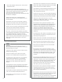
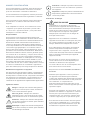
Symbols used
Caution: Indicates a hazardous situation
which, if not avoided, could result in minor
or moderate injury.
Danger: Indicates a hazardous situation
which, if not avoided, will result in death or
serious injury.
Warning: Indicates a hazardous situation
which, if not avoided, could result in death
or serious injury.
Notice: Indicates a situation which, if not
avoided, could result in damage to property.
Note: Indicates useful information which
helps in getting the most out of the product.
NOTICE
Important: Indicates significant information
which is essential for the product to function
correctly.
Hazard information
Mounting, installation and servicing work on
electrical devices may only be performed by
a qualified eletrician. Failure to observe this
regulation could result in the risk of serious
damage to health or fatal injury due to electric
shocks.
Devices with 110-240 V connection: The device
may only be connected to an easily accessible
power socket outlet. The mains adapter must
be pulled out if a hazard occurs.
For power supply, only use the original
plug-in mains adapter delivered with the
device or a recommended PoE-Switch/
PoE-Injector as specified in this manual.
Because of electrostatic charging, direct
contact with the circuit board can result in
destruction of the device. Direct contact
with the circuit board must therefore be
avoided at any time.
Observe the EN 60065 resp. EN 60950 resp.
EN 62368 standard.
Do not use the device if there are signs of
damage to the housing, control elements or
connecting sockets, for example, or if it
demonstrates a malfunction. If you have any
doubts, please have the device checked by
an authorized expert.
Do not open the device. This voids the
warranty of the device. The device does not
contain any parts that can be maintained
by the user. In the event of an error, please
have the device checked by an authorized
expert.
For safety, approval and licensing reasons
(CE/FCC/IC etc.), unauthorized change and/or
modification of the device is not permitted.
The device is not a toy; do not allow
children to play with it. Do not leave packaging
material lying around. Plastic films/bags,
pieces of polystyrene, etc. can be dangerous
in the hands of a child.
Always lay cables in such a way that they
do not become a risk to people and domestic
animals.
WARNING

ENGLISH
3
Voltage is applied to parts within the
equipment. Do not touch any parts that are
not associated with the installation, wiring,
or connection. Electric shock could result.
On devices which are not marked as
weather-proof: Keep the device away from
water or any other liquid.
Do not install or make any wire terminations
while power supply is plugged in. It can cause
eletric shock or damage to the device.
Before turning on power, make sure wires are
not crossed or shorted. If not, fire or eletric
shock could result.
High voltage may be present internally.
Do not open the device. Electric shock could
result.
The device is not of explosion-proof. Do not
install or use near gases or flammable
materials. Fire or explosion could result.
Do not install two power supplies in parallel
to a single input. Fire or damage to the device
could result. Be sure to connect a single
power supply to the device.
Do not connect any terminal on the device
to an AC power line. Fire or electric shock
could result.
Keep AC cord from being marred or crushed.
If the AC cord is fractured, fire or electric shock
could result.
Do not plug or unplug with wet hands.
Electric shock could result.
Do not put any metal or flammable material
into the device. Fire, electric shock, or device
trouble could result.
Existing wiring may contain high voltage AC
electricity. Damage to the device or electric
shock could result. Wiring and installation
must be done by a qualified eletrician.
When mounting the device on a wall or
ceiling, install the device in a convenient
location, but not where it could be jarred or
bumped. Injury could result.
On devices with ground terminals, connect to
an earth ground. Otherwise fire or malfunction
could result.
WARNING
On devices with plastic or real glass, do not put
high pressure on the glass. If fractured, injury
could result.
On devices with LCD, if LCD is punctured, do
not allow contact with the liquid crystal inside.
Injury could result. If necessary, gargle your
mouth and clean your eyes or skin with clear
water for at least 15 minutes and consult your
doctor.
Do not put anything on the device or cover the
device with cloth, silicone, glue, coating,
separate covering etc. Fire or device issues
could result.
Do not install the device in any of the following
locations. Fire, electric shock, or device trouble
could result.
- Places under direct sunlight or places near
heating equipment that varies in temperature.
- Places subject to dust, oil, chemicals,
hydrogen sulfide (hot spring).
- Places subject to moisture and humidity
extremes, such as bathrooms, cellars,
greenhouses, etc.
- Places where the temperature is very low,
such as inside a refrigerated area or in front of
an air conditioner.
- Places subject to steam or smoke (e.g. near
heating or cooking surfaces).
- Where noise generating devices such as
dimmer switches or inverter electrical
appliances are closeby.
- Locations subject to frequent vibration or
impact.
On devices with intercom, be sure to perform
a call test with low audio volume on both
intercom devices. A sudden call etc. may arrive
causing for example damage to your ear.
If the device does not operate properly, unplug
the power supply.
All devices which are not marked as weat
her-proof are designed for indoor use only.
Do not use outdoor.
On devices which are marked weather-proof:
Do not spray with high-pressure water. Device
issues could result.
We do not assume any liability for damage
to property or personal injury caused by
improper use or the failure to observe the
hazard information. In such cases, any claim
under warranty ceases. For consequential
damages, we assume no liability!

4
manufactured with very high precision
techniques, inevitably will have a very small
portion of its picture elements always lit
or not lit at all. This is not considered a device
malfunction.
On devices with intercom, due to the
environmental sound around the device, it
may hinder smooth communication, but
this is not a malfunction.
On devices with Username/Password, the
Username/Password to access the device is
the customer‘s responsibility. Make sure to
use password that cannot be easily guessed
by a third party. We recommend that you
change the Password on a regular basis.
We will, under no circumstances, be liable for
damage that occurs due to failures in power
supply, network equipment or terminal
devices; failures due to Internet providers and
cellular network providers; failures such as
disconnected lines and other losses in
communication, which makes it impossible
to provide this service as well as in any way
delay this service due to any other causes
outside of our responsibility; or if an error or
missing data occurs during transmission.
Safety instructions
The device shall be used in compliance with
local laws and regulations.
Store the device in a dry and ventilated
environment.
Avoid exposing the device to shocks or heavy
pressure.
Do not install the device on unstable brackets,
surfaces or walls. Make sure the material is
strong enough to support the weight of the
device.
Use only applicable tools when installing the
device. Using excessive force with tools could
cause damage to the device.
Do not use chemicals, caustic agents, or aerosol
cleaners.
Use a clean dry cloth for cleaning.
Use only accessories that comply with technical
specification of the device. These can be provided
by Bird Home Automation GmbH.
Use only spare parts provided by or
recommended by Bird Home Automation GmbH.
Do not attempt to repair the device by yourself.
Contact Bird Home Automation GmbH for
service matters.
Keep the device more than 1 m (3.3‘) away
from microwave, radio, TV, wireless router and
any other wireless devices.
On devices with intercom or built-in speaker or
built-in microphone or signal transmission
functions, keep the wires more than 30 cm (12‘‘)
away from AC 100-240 V wiring. AC induced
noise and/or device malfunction could result.
Install the device in an area that will be
accessible for future inspections, repairs and
maintenance.
If the device is used close to a cellular phone,
the device may malfunction.
The device can be damaged if dropped.
Handle with care.
The device turns inoperative during power
failure.
On devices with intercom or built-in speaker
or built-in microphone, in areas where
cellular or Radio / TV broadcasting station
antennas are closeby, the device may be
affected by radio frequency interference.
On devices with LCD screen, it must be noted
in advance that the LCD panel, though
NOTICE
Warranty Information
For information about the device warranty, see
www.doorbird.com/warranty
Transportation
When transporting the device, use the
original packaging or equivalent to prevent
damage to the device.
NOTICE

ENGLISH
5
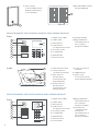
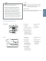
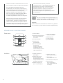
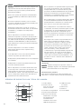
DEVICE EXAMPLE WITH CALL BUTTON
1) HDTV Video
2) Light Sensor
For night-vision mode
3) Security screws
4) Motion Sensor
5) Illuminated
call button with
nameplate
The illumination is
also acting as
Diagnostic LED(s).
1) Main Electrical Unit
2) Yellow cable for
call button
Connected to
the illuminated call
button with
nameplate
3) Red cable for Module
Port 1(unused)
Inside
Front
1
2
3
4
5
6
7
8
9
5
6
7
1
2
3
4
6) Night Vision LEDs
7) Microphone
8) Loudspeaker
9) RFID Reader
4) Green cable for
Module Port 2
(unused)
5) Screw connection
terminal
6) LAN/PoE jack
7) Nylon cord
To secure the front
panel during assembly
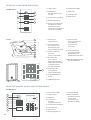
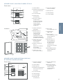
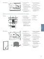
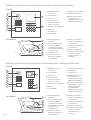
DEVICE EXAMPLE WITH AND MORE CALL BUTTONS
Front 1) HDTV Video
2) Light Sensor
For night-vision mode
3) Security screws
4) Motion Sensor
5) Illuminated call
buttons
with nameplate
The illumination is
also acting as
Diagnostic LED(s).
6) Night Vision LEDs
5
1) Main Electrical Unit
2) Velcro tape 1
To fix the Multi
Tenant Module
temporary on the
Main Electrical
Unit during assembly
3) Yellow cable for
call button (unused)
4) Red cable for
Module Port 1
Connected to Multi
Tenant Module
Inside
5
6
7
8
1
2
3
4
7) Microphone
8) Loudspeaker
9) RFID Reader
5) Green cable for
Module Port 2
(unused)
6) Screw connection
terminal
7) LAN/PoE jack
8) Nylon cord
To secure the front
panel during assembly
1
2
3
4
6
7
8
9

6
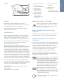
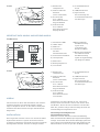
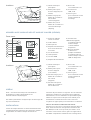
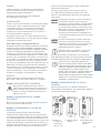
DEVICE EXAMPLE WITH DISPLAY MODULE AND KEYPAD MODULE
9) Display Module
10) Keypad Module
The illumination is
also acting as
Diagnostic LED(s)
1) Night Vision LEDs
2) HDTV Video
3) Microphone
4) Light Sensor
For night-vision mode
5) Security screws
6) Loudspeaker
7) RFID Reader
8) Motion Sensor
Front
9) Velcro tape 2
To fix the Multi Tenant
Module permanently
on the backbox
10) DoorBird Multi Tenant
Module MTM18A
1
2
3
4
5
6
7
8
9
10
1) Main Electrical Unit
2) Yellow cable for
call button (unused)
3) Red cable for
Module Port 1
Connected to the
Keypad Module
4) Green cable for
Module Port 2
Connected to the
Display Module
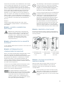
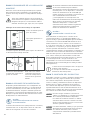
1) Night Vision LEDs
2) HDTV Video
3) Microphone
4) Light Sensor
For night-vision mode
5) Security screws
6) Loudspeaker
7) RFID Reader
8) Motion Sensor
9) Info Module
Inside
5
6
7
2
3
4
1 5) Screw connection
terminal
6) LAN/PoE jack
7) Nylon cord
To secure the front
panel during assembly
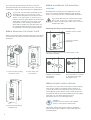
10) Keypad Module
The illumination is
also acting as
Diagnostic LED(s)
11) Illuminated
call button with
nameplate
The illumination is
also acting as
Diagnostic LED(s).
9
10
DEVICE EXAMPLE WITH INFO MODULE AND KEYPAD MODULE
Front
1
2
3
4
5
6
7
8
9
10
11

ENGLISH
7
VIDEOS
Need help with the installation? Be sure to
watch our installation videos which can be found
on http://www.doorbird.com/support
Each individual step of the installation is clearly
documented in the videos.
INSTALLATION
All the steps below should be carried out carefully
by a competent adult, taking into consideration any
applicable safety regulations. Please contact us
directly or seek the advice of a compeent specialist.
Please ensure that all wires used for the installation
are undamaged along their entire length and
approved for this type of use.
Network speed and network components
Please ensure that the upload speed of your Internet
connection is at least 0.5 Mbps. You can also carry
out a speed test at any time via the DoorBird App.
The user experience is only as good as your network
speed, network stability and quality of your network
components, such as your Internet Router and WiFi
access points or WiFi repeaters. Please also make sure
that your network components are no older than two
years old, have been manufactured by a well-known
manufacturer, and have the latest firmware installed.
Should these requirements not be fulfilled, it may
occur, for example that the performance of audio and
video is poor or push notifications are delayed or do
not arrive on your smartphone or tablet at all.
Requirements:
High-speed Internet (via landline): DSL, cable or
optical fibre
Network: Ethernet, with DHCP
Inside 1) Main Electrical Unit
2) Yellow cable for
call button (unused)
3) Red cable for
Module Port 1
Connected to the
Keypad Module
4) Green cable for
Module Port 2
Connected to the
Info Module
5
6
7
1
2
3
4
5) Screw connection
terminal
6) LAN/PoE jack
7) Nylon cord
To secure the front
panel during assembly
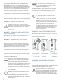
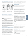
STEP 1: SWITCHING OFF POWER
Switch off the power to all wires leading to
the assembly location, i.e. the door chime,
electric door opener, power supply unit for
the video door station etc.
STEP 2: DISMANTLING THE EXISTING
DOORBELL
Should there already be a doorbell or door station on
the exterior wall of the house, please dismantle it.
STEP 3: DETERMINING THE ASSEMBLY
LOCATION
The device uses an ultra wide-angle hemispheric lens
so that even when the person is a minimum distance
of 50 cm (19.68 in) away from the device, a low
installation height is sufficient. The lens is therefore not
mechanically adjustable. The camera lens should be
located at an altitude of at least 145 cm (57 in).
You may check this prior to the final mounting.
When choosing the assembly location, consider
the lighting conditions. Avoid direct sunlight, direct
backlight and reflective surfaces.
NOTICE Do not expose the device to direct sunlight.
The housing temperature can exceed the
maximum allowed temperature limit. This can
result in damage of electric and mechanic
components of the device and injuries
especially when touching exterior parts of the
device. White and bright silver-colored front
plates absorb less sunlight than dark ones.
NOTICE An image sensor must not be exposed to
direct sunlight for an extended period of time.
Direct sunlight will “blind” the camera and
may permanently bleach the small color filters
on the image sensor chip.
Any defects caused by direct sunlight are not
covered by warranty.

8
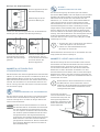
STEP 5: ASSEMBLING THE MOUNTING
HOUSING
Assemble the mounting housing (backbox) to the
wall. You can find detailed drawings and measure-
ments of the device in the corresponding datasheet.
If you must drill holes in a wall, insert screws
into a wall or lever up a wall, ensure that
no cables or mains (gas, water, etc.) are to be
found in the wall.
The network cable between the device and the
PoE-Switch/PoE-Injector/Internet Router can have a
maximum length of 80 meters/262 feet (IEEE 802.3).
If you have only two wires available at the
assembly location, you may use of the
“DoorBird 2-Wire Ethernet PoE Converter
A1071”, sold separately. It allows you to
transfer network data (Ethernet) and power
(PoE) with a simple two-wire cable over
long distances. For example; existing buil-
dings with a simple two-wire bell wire can
be equipped with network technology wit-
hout having to retrofit any network cables.
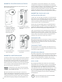
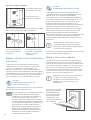
STEP 4: REMOVING THE FRONT PLATE
Remove the front plate carefully using the screw driver
provided with the device from the mounting housing
(backbox).
2.) Pull down the
front panel.
3.) Pull the front panel
towards you.
1cm
1.) Turn out the security
screws for 1 cm
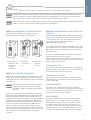
STEP 6: POWER SUPPLY OPTIONS
The device can be powered using the power-supply
unit (mains adaptor) supplied with it (Option 1)
or via PoE (Power over Ethernet) using a network
cable (Option 2). The device can be alternatively also
be supplied with power using a DIN-rail power supply
unit that you can obtain direclty from us.
The device does not use battery power.
OPTION :
POWER SUPPLY USING THE POWER
SUPPLY UNIT (MAINS ADAPTOR)
The power supply unit (mains adaptor) supplied
with the device has a 300 c m long cable with two
insulated wires.
Mounting the surface-mounted housing
Place the rubber seal for the cable entry on the
mounting opening.
Pierce through the
middle of the rubber
seal using a
screwdriver.
Feed all cables and wires
that you want to connect
to the device through
the rubber seal.
Rubber seal for cable
entry
Cover for unused
openings

ENGLISH
9
You can use the nylon
cord to temporary fix the
front plate to the mounting
housing (backbox) while
connecting the cables and
wires to the device.
NOTICE Do not plug the power supply unit into the
wall socket yet. Only use the power supply
unit provided along with the device, or a
DIN-rail power supply unit that you can obtain
from us separately, since this has been
specially stabilized electrically and is
equipped with an integrated audio inter-
ference reduction device. Other power
supply units may destroy the device or
cause poor transmission quality.
The warranty expires automatically if you
use a different power supply unit.
OPTION :
POWER SUPPLY AND NETWORK
CONNECTION USING POE (POWER OVER
ETHERNET)
To power the device via a PoE-Switch (e.g. D-Link
DGS-1008P) or PoE-Injector (e.g. DoorBird Gigabit PoE
Injector A1091) in accordance with the PoE standard
IEEE 802.3af Mode A, the four wires bearing the
numbers 1, 2, 3 and 6 of a Cat.5 cable or better are
to be used. A Cat.5 cable or better must be used
as network signals can only be transmitted over
completely insulated, shielded and twisted cables.
If you use PoE as a source of power the four wires for
PoE then simultaneously form the data link.
The device won’t start if your PoE-Switch/PoE-Injector
does not support the PoE Standard IEEE 802.3af
Mode A (see Diagnostic-LED and Diagnostic-Sounds).
1. Disconnect the PoE-Switch or PoE-Injector
from the power grid.
2. Run the network cable to the installation
location of the device.
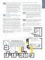
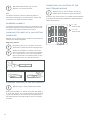
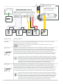
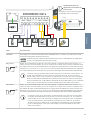
STEP 7: CONNECTING THE DEVICE
It is possible to connect the cables and wires to the
device conveniently and safely via labelled connection
ports. You can connect all necessary cables and wires
to the device now. Please remove any cables and wires
from the connection ports of the device that you do
not need. Remove about 5 mm of insulation material
at the end of the wires that you would like to connect
to the green screw connection terminal of the device.
NOTICE Please take care when connecting the cables
and wires. Connecting the cables and wires
the wrong way may damage the device.
Wires without insolation material must not
protrude out of the green screw connection
terminal, it may lead to electrical short and
damage the device.
NOTICE The yellow, green, and red cables that lead
out from the side of the Main Electrical Unit
must only be used to connect components
certified by Bird Home Automation.
Handle the front plate with care. The surface
of the front plate could be scratched or
otherwise damaged if handled without care.
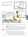
DOORBIRD D21x
Only related for devices
with call button(s)
4 Pin
Each Call Button is
equipped with one jack.
REL REL VDCEXT

10
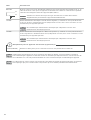
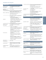
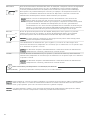
PORT DESCRIPTION
LAN/POE RJ45 jack to connect a standard Network cable Cat.5 or better, coming from the Internet
Router/PoE-Switch/PoE-Injector.
NOTICE Do not power the device simultaneously via the power supply from the power
supply unit (mains adaptor) and the power supply via PoE.
REL1, REL1
REL1
REL1
Bi-stable latching relay #1, max. 24 V DC/AC, 1 Ampere. Security feature: The relay keeps
its state even in the case of loss of power. You can configure the default state of the relay
(open/close) via the DoorBird App. These ports can be used to connect e.g. an electric door
opener. The device does not supply power to the connected device. The power supply for
the electric door opener must be installed separately.
When wiring an electric door opener directly to a door station, there is a risk that
the electric door opener could be tampered by unauthorized third parties (e. g. by
breaking the door station and short-circuiting the wiring of the door opener).
Therefore, we generally recommend the use of a remote safety relay mounted
indoors (e. g. DoorBird I/O Door Controller A1081) for wiring an electric door
opener for a more secure installation in your home.
REL2, REL2
REL2
REL2
Bi-stable latching relay #2, max. 24 V DC/AC, 1 Ampere. Security feature: The relay keeps
its state even in the case of loss of power. You can configure the default state of the relay
(open/close) via the DoorBird App. These ports can be used to connect e.g. an electric door
opener. The device does not supply power to the connected device. The power supply for
the electric door opener must be installed separately.
When wiring an electric door opener directly to a door station, there is a risk that
the electric door opener could be tampered by unauthorized third parties (e. g. by
breaking the door station and short-circuiting the wiring of the door opener).
Therefore, we generally recommend the use of a remote safety relay mounted
indoors (e. g. DoorBird I/O Door Controller A1081) for wiring an electric door
opener for a more secure installation in your home.
BELL, BELL
NOTICE Reserved – Do not use!
EXT, EXT
EXT
EXT
Door opener button, max. 0 V DC/AC, 0 Ampere. These ports can be used to connect e.g.
a door opener button inside the home. It will trigger the first bi-stable latching relay of the
device (REL1, REL1).
NOTICE Please make sure to add no voltage on these ports. Extra voltage may destroy
the device immediately.
15 VDC - 15 V DC Power supply input, negative pole (-). Please connect the black wire of the power
supply unit (mains adaptor) supplied with the device here, if you do not power the device
using PoE.
NOTICE Do not power the device simultaneously via the power supply from the power
supply unit (mains adaptor) and the power supply via PoE.
15 VDC + 15 V DC Power supply input, positive pole (+). Please connect the red wire of the power
supply unit (mains adaptor) supplied with the device here, if you do not power the device
using PoE.
NOTICE Do not power the device simultaneously via the power supply from the power
supply unit (mains adaptor) and the power supply via PoE.

ENGLISH
11
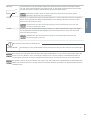
Only related for devices with call button(s):
4 PIN (SWITCH) Use the yellow cable to connect the button to the IP Video Door Station.
Please take care when connecting the cables and wires. Connecting the cables and wires the wrong
way may damage the device. Wires without insolation material must not protrude out of the green
screw connection terminal, it may lead to electrical short and damage the device.
The yellow, green, and red cables that lead out from the side of the Main Electrical Unit must only be
used to connect components certified by Bird Home Automation.
NOTICE
NOTICE
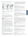
STEP 9: ACTIVATING THE DEVICE
Switch on the power leading to the assembly location
again. If you use PoE, make sure to switch on power
of the PoE-Switch or PoE-Injector you have connected
the device to.
NOTICE Do not power the device simultaneously via
the power supply from the power supply
unit (mains adaptor) and the power supply
via PoE.
You can see if the device is powered by checking the
Diagnostic-LED, which lights up after about 30 to 60
seconds after the power is connected. The device is
ready for operation (booting up process, any software
updates, etc.) once it has emitted a short diagnosis
sound from the integrated loudspeaker. This may last
for up to 5 minutes. If the Diagnostic LED does not
light up, please check the power supply. Please
also check whether you have used a wall-plug power
supply and not PoE and whether you have connected
the positive pole and negative pole to the device
correctly.
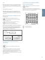
STEP 8: ASSEMBLING THE FRONT PLATE
Assemble the front plate of the device to the
mounting housing (backbox) of the device.
1.) Pull the front
panel into the
mounting
housing
(backbox)
2.) Push the
front panel
up.
3.) Insert the
security
screws.
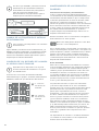
STEP 10: DOWNLOADING AND INSTALLING
THE APP
Download the “DoorBird” App by Bird Home Automation
onto your mobile device from the Apple App Store
or Google Play Store. You can always find the most
up-to-date version of the App manual on
www.doorbird.com/support
Go to DoorBird App “Settings > Add device” and click
on the QR code icon in the “User” field. Scan the user
QR code found on the “Digital Passport” provided
with the device.
If you have problems adding the device to the App
please check if the device is online
(www.doorbird.com/checkonline). If the device is not
online, please check the network connection and the
power supply of the device.
DIAGNOSTIC-LED
You can see if the device is powered by checking the
Diagnostic-LED, which lights up after about 30 to 60
seconds after the power is connected.
DIAGNOSTIC-SOUNDS
After around one to five minutes, the device emits
brief diagnostic sounds after it has been connected
to the power grid.
MOTION SENSOR
The device has a built-in Motion Sensor with 4D
Technology. You can use it for numerous applications,
e. g. to send an alarm to a mobile device or to switch
a relay to turn on an outdoor light.
RFID READER
The built-in RFID reader can be used for many
applications, e.g. to open/lock doors or arming/
disarming your alarm system. For security reasons,
the RFID reader has a very short range (0 - 3 cm,
0 - 1.18 in), so you must place the compatible RFID
tag (key fob) very close to the RFID reader. You can
configure the RFID reader using the DoorBird App.

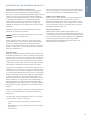
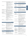
12
1= 1. call
button jack
18 = 18. call
button jack
CHANGING THE LABEL OF THE INFO MODULE
Applies only to devices with Info Module.
Please follow STEP 1 to switch off power and STEP 2
to open the device. You can then change the labeling
of the Info Module in the inside. We recommend to
use white paper for the label which does not absorb
moisture.
18
12
6
17
11
5
16
10
4
15
9
3
14
8
2
13
7
1
The RFID reader works only on short
distance, for security reasons.
API
The device features a well documented API for
third-party integration. For information, terms and
conditions see www.doorbird.com/api
DOORBIRD CONNECT
The device features many options to integrate it into
third-party applications. For information, terms and
conditions see www.doorbird.com/connect
CHANGING THE LABEL OF A CALL BUTTON
NAMEPLATE
Applies only to devices with 1 and more illuminated
call buttons with nameplate.
Engraving Service
Engraving service for a modern and clean
appearance: www.doorbird.com/engraving
Please follow STEP 1 to switch off power.
We recommend to use a thin slot screwdri-
ver to remove the cover of the nameplate.
We recommend to use white paper for the
label which does not absorb moisture.
CONNECTING CALL BUTTONS TO THE
MULTI TENANT MODULE
Applies only to devices with 2 and more
illuminated call buttons with nameplate.
Connect only call buttons to the Multi Tenant Module
(e.g. Multi Tenant Module MTM18A) certified by Bird
Home Automation.

ENGLISH
13
MAINTENANCE FOR DOORBIRD PRODUCTS
Cleaning and maintenance instructions
All DoorBird door stations are made of high-quality
materials and are designed for a durable lifetime.
Since door stations are usually installed in unprotected
outdoor areas, they are exposed to adverse weather
conditions and aggressive substances, especially close
to frequently used roads, in coastal and industrial
areas. Therefore please consider the following care
instructions. Unfortunately, we cannot accept any
liability for damage if these instructions are not being
observed.
Aggressive dirt such as bird droppings should be
removed as quickly as possible.
NOTICE Never use abrasive detergents such as steel
wool or scouring milk!
Warm water is usually sucient, if necessary with
a little detergent, a soft cloth or brush. Plastic parts
(camera or name tags) must not be treated with
metal care products. Remove all residues of cleaning
agents or lubricants to avoid stains or discolouration
after the maintenance.
Stainless Steel
Only high-quality German stainless steel is used for all
available DoorBird door stations. However, high-quality
stainless steel can also rust, as approx. 70% of stainless
steel is made of iron. Rust resistance is only achieved
by a protective layer (also called passive layer), which
covers the iron like a skin. This protective layer consists
essentially of chromium and other precious metals.
Iron particles, grinding dust and chips deposited on
stainless steel can lead to corrosion (rust film). These
iron particles can be found everywhere, but especially
in coastal and industrial areas and close to frequently
used roads. Please remove ferrous deposits immediately,
as they will attack your door station and lead to real
rust if not removed. To remove rust, simply wipe off the
dust; in addition, a care product is recommended, e.g.
WD 40, available e.g. at Amazon for less than € 5.00.
Simply apply in a thin layer and rub in. The same applies
if rust appears on the engravings on the stainless steel
surface.
Cement or lime splashes should be carefully removed
as soon as possible with a wooden spatula before
hardening.
The following cleaning detergents are not to be used
as they reduce corrosion resistance:
• products containing chloride and hydrochloric
acid
• Bleach (in case of accidental use, rinse thoroughly
with water)
• Silver polish
After the cleaning with clear water wipe with damp
cloth and rub dry to avoid lime traces. Lime residues
can be avoided by using demineralised water.
Stainless steel PVD coated
PVD coated, chrome-plated or gold-plated surfaces
are recommended to be cleaned with a grease-
dissolving detergent and clear water or with a clean
and dust-free microfibre cloth. For high-gloss surfaces,
use a scratch-free cloth (e.g. cleaning cloth for glasses,
furniture polishing cloth, etc.).
Lacquered surfaces
Clean painted surfaces and lettering with a soft,
scratch-free cloth moistened with a mild soap solution
(e.g. cleaning cloth for glasses, furniture polishing cloth,
etc.). To prevent stains or discolouration, the detergents
should be wiped off without leaving any residue.
Be particularly careful with lettering in order not to
damage the film or the print.

14
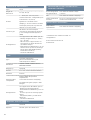
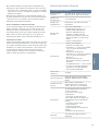
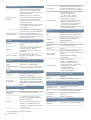
TECHNICAL SPECIFICATIONS CURRENT SYSTEM REQUIREMENTS
System
requirements
Mobile device: Newest iOS on
iPhone/iPad, newest Android on
Smartphone/Tablet
Internet: High-Speed Landline
Broadband Internet connection,
DSL, cable or fiber optic, no socks
or proxy server
Network: Ethernet Network, with
DHCP
Recommended
installation height
Camera lens should be at a min.
height of 145 cm (57 in). Before
the installation please determine
your optimal installation height.
VIDEO
Camera
HDTV 720p, dynamic
(VGA – HDTV)
Lens
High-end ultra wide-angle
hemispheric lens 180° (D), 140° (H),
100° (V), straightened, IR-capable
Night-vision
Yes, light sensor, automatic IR-cut
filter, 12 Infrared LEDs (850 nm)
AUDIO
Audio
components
Speaker and microphone, noise
reduction and echo cancellation
(ANR, AEC)
Audio streaming
Two-way, full duplex
NETWORK
Ethernet
RJ45 jack, PoE 802.3af Mode-A,
10/100 Base-T
Supported
protocols
HTTP, HTTPS, SSL/TLS, Bonjour,
DNS, RTSP, RTP, TCP, UDP, RTCP,
ICMP, DHCP, ARP, SIP, DTMF (RTP
[RFC-2833], SIP INFO [RFC-2976]),
STM
MOTION SENSOR
Type
Active
Detection angle
54° (H), 70° (V)
Range
1 - 10 m (3.3 - 32.9 ft), depends on
environment, configurable in 1 m
(3.3 ft) steps.
If a “Display Module” is connected
to the Main Electrical Unit, the
range is limited to 1 m (3.3 ft).
Technology
4D. Based on multiple integrated
sensors and algorithms, e.g. Radio
Frequency Energy (RFE)
Configuration
Via App, e.g.
• Range (1 - 10 m / 3.3 - 32.9 ft)
• Movement direction (coming,
leaving, both)
• Individual events (e.g. switch a
relay, push notification, SIP call
[audio/video], HTTP(s)
notification)
• Individual schedules
GENERAL
Power supply
15 V DC (max. 15 W) or Power over
Ethernet (PoE 802.3af Mode-A)
Info Module*
3.5″, illuminated
Display Module*
3.5″ LCD (no touch function),
illuminated, for the display of
a 2-line free text and the name
directory (max. 100 entries)
Keypad Module*
16 keys, illuminated, configurable
via App, e.g.
• Individual PIN codes
• Individual events (e.g. switch a
relay, push notification, SIP call
[audio/video], HTTP(s) request)
• Individual schedules
• Up to 100 PIN codes manageable
Connectors
• RJ45, for LAN/PoE
• Bi-stable latching relay #1,
max. 24 V DC/AC, 1 Ampere, e.g.
for electric door opener
• Bi-stable latching relay #2,
max. 24 V DC/AC, 1 A, e.g. for
electric door opener
• External input for external door
opener button (potential-free)
• 15 V DC input (+, -), max. 15 W
• Relays can be expanded /
detached with DoorBird I/O Door
Controller
Weather-proof
Yes, IP65
Approvals
IP65, CE, FCC, IC, RoHS, IK08,
REACH, IEC/EN 62368, IEC/EN
62471
Operating
conditions
-25 to +55°C / -13 to 131°F
Humidity 10 to 85 % RH
(non-condensing)
Scope of delivery
1x Main Electrical Unit
1x Front panel*
1x Mounting housing (backbox)*
1x Power supply unit (mains
adaptor) with four country-
specific outlet adaptors
(110 - 240 V AC to 15 V DC)
1x RFID key fob
1x Screwdriver
1x Quickstart guide with Digital
Passport
1x Installation manual
1x Small parts
Warranty
see www.doorbird.com/warranty
* Only contained in certain models or configurations

ENGLISH
15
RFID
Type
Active Reader Passive Tag (ARPT)
system
Standard
ISO/IEC 18000-2:2009 Part 2,
EM4100, EM4102
Frequency
125 KHz
Range
0 - 3 cm, depends on environment
Antenna
Internal
Compatible
Transponder
RFID key fobs, sold separately,
see www.doorbird.com/buy
Up to 100 tags manageable
Configuration
Via App, e.g.
• Tag (add, delete)
• Individual events (e.g. switch a
relay, push notification, SIP call
[audio/video], HTTP(s)
notification)
• Individual schedules
INTEGRATED WIRELESS MODULES
RFID
125 KHz
Sensor
24 GHz, can be disabled
THIRD-PARTY INTEGRATION (DOORBIRD CONNECT)
Partnerintegrations see www.doorbird.com/connect
API see www.doorbird.com/api
Simultaneous
video streams
One, for event-based and
continuous
recording
OPTIONAL ACCESSORIES
Sold separately
see www.doorbird.com/buy
LEGAL NOTES
General remarks
1. DoorBird is a registered trademark of Bird Home Automation
GmbH.
2. Apple, the Apple logo, Mac, Mac OS, Macintosh, iPad, Multi-Touch,
iOS, iPhone and iPod touch are trademarks of Apple Inc.
3. Google, Android and Google Play are trademarks of Google, Inc.
4. The Bluetooth® word mark and logos are registered trademarks of
Bluetooth SIG, Inc.
5. All other company and product names may be trademarks of the
respective companies with which they are associated.
6. We reserve the right to make changes to our products in the
interests of technical advancement. The products shown may also
look different from the products supplied based on ongoing
enhancement.
7. Reproducing or using texts, illustrations and photos from this
instruction manual in any media – even if only in the form of excerpts
– shall only be permitted with our express written consent.
8. The design of this manual is subject to copyright protection. We
do not accept any liability for any errors or any erroneous content or
printing errors (even in the case of technical specifications or within
graphics and technical sketches).
9. Our products are in compliance with all technical guidelines,
electrical and telecommunications regulations applicable in
Germany, the EU and the USA.
Data privacy and data security
1. For maximum security, the device uses the same encryption
technologies as are used in online banking. For your security, no port
forwarding or DynDNS is used either.
2. The data centre location for remote access over the Internet by
means of an App is obligatory in the EU if the determined Internet
IP-Address location of the device is within the EU. The data centre is
operated in line with the most stringent security standards.
3. Video, audio and any other surveillance methods can be regulated
by laws that vary from country to country. Check the laws in your
local region before installing and using this device for surveillance
purposes.
If the device is a door-, indoor station or camera:
In many countries video and voice signal may only be transmitted
once a visitor has rung the bell (data privacy, configurable in the App).
Please carry out the mounting in such a way that the detection
range of the camera limits the device exclusively to the immediate
entrance area.
The device may come with a visitor history and motion sensor. You
can activate/deactivate this function if required.
If necessary, indicate the presence of the device in a suitable place
and in a suitable form.
Please observe any relevant country-specific statutory regulations
concerning the use of surveillance components and surveillance
cameras applicable at the installation site.
Check with the property owner and your house community if you are
allowed to install and use this product. Bird Home Automation GmbH
cannot be held responsible for any miss-use or miss-configuration of
this product, including the unauthorized opening of a door.
Bird Home Automation cannot be held responsible for damages
caused by improper existing installations or improper installation.
Software and operating system’s updates (so-called “firmware
updates”) are generally automatically installed on the products of
Bird Home Automation GmbH via Internet, if technically possible.
Automatic firmware updates keep the products‘ software up to date
so that they always work reliably, safely and efficiently. Through
further development, features can be added, extended or slightly
changed. Major changes or limitations to existing features will
generally occur if Bird Home Automation GmbH deems it necessary
(e.g. for data protection, data security or stability reasons, or to keep
them up to date). When a firmware update is available, Bird Home
Automation GmbH‘s servers generally automatically distribute it to
all compatible products connected to the Internet or Bird Home
Automation GmbH‘s servers. This process is gradual and can take
several weeks. As soon as a product receives a firmware update, the
system will be installed and will restart by itself. Installed firmware
updates cannot be undone. Since the products and software of
Bird Home Automation GmbH are not explicitly customer-specific
products, a customer cannot deny an automatic update if the
product is connected to the Internet or to the Bird Home Automation
GmbH’s server.
Instructions for disposal
Do not dispose of the device with regular domestic waste. Electronic
equipment must be disposed e.g. at local collection points for waste
electronic equipment in compliance with the Waste Elec trical and
Electronic Equipment Directive.
Publisher
Bird Home Automation GmbH
Uhlandstraße 165
10719 Berlin
Germany
Web: www.doorbird.com
Email: hello@doorbird.com
Errors and omissions excepted.

16
INSTALLATIONSANLEITUNG
Lesen Sie diese Anleitung sorgfältig, bevor Sie die
Komponenten in Betrieb nehmen. Bewahren Sie die
Anleitung zum späteren Nachschlagen auf!
Wenn Sie das Gerät anderen Personen zur Nutzung
überlassen, übergeben Sie auch diese Bedienungs-
anleitung.
Die stets aktuelle Version der Installationsanleitung
finden Sie unter
www.doorbird.com/de/support
Zur Vereinfachung der Begriffe verwenden wir „Gerät“
für das Produkt „IP Video Türstation“ sowie „mobiles
Endgerät“ für ein Smartphone/Tablet.
Haftung
Die Erstellung dieses Dokuments wurde sorgfältig
vorbereitet. Bitte infor mieren Sie Bird Home
Automation GmbH über etwaige Ungenauigkeiten
oder Unterlassungen. Bird Home Automation GmbH
kann nicht für tech nische oder typografische Fehler
verantwortlich gemacht werden und behält sich das
Recht vor, Änderungen an dem Produkt und den
Handbüchern ohne vorherige Ankündigung vorzu-
nehmen. Bird Home Automation GmbH übernimmt
keinerlei Garantie in Bezug auf das in diesem Doku-
ment enthaltene Material, einschließlich, aber nicht
beschränkt auf die implizierten Garantien der
Marktgängigkeit und Eignung für einen bestimmten
Zweck. Bird Home Automation GmbH haftet nicht
für Neben- oder Folgeschäden im Zusammenhang mit
der Bereitstellung, Durchführung oder Verwendung
dieses Materials. Das Gerät darf nur für den vorgesehe-
nen Zweck verwendet werden.
Gerätemodifikationen
Dieses Gerät muss in Übereinstimmung mit den
Anweisungen in der Installationsanleitung installiert
und verwendet werden. Dieses Gerät enthält keine
vom Benutzer zu wartenden Komponenten. Durch
unbefugte Gerätemodifikationen oder Änderungen
erlöschen alle anwendbaren Zertifizierungen und
Zulassungen.
Verwendete Symbole
Achtung: Weist auf eine gefährliche Situ-
ation hin, die, falls nicht verhindert, zum
Tod oder schweren Verletzungen führt.
Warnung: Weist auf eine gefährliche
Situation hin, welche, falls nicht verhindert,
zum Tod oder schweren Verletzungen
führen kann.
Bitte beachten: Weist auf eine gefährliche
Situation hin, welche, falls nicht verhindert,
zu Sachschäden führen kann.
Hinweis: Weist auf nützliche Informationen
hin, die die optimale Verwendung des
Geräts unterstützen.
NOTICE
Wichtig: Weist auf wichtige Informationen
hin, die den richtigen Betrieb des Produkts
gewährleisten.
Vorsicht: Weist auf eine gefährliche Situ-
ation hin, welche, falls nicht verhindert,
zu geringfügiger oder mäßiger Verletzung
führen kann.
Gefahrenhinweise
Einbau, Montage und Servicearbeiten elek -
trischer Geräte dürfen ausschließlich durch
eine Elektrofachkraft erfolgen. Bei Nichtbeachten
besteht die Gefahr schwerer gesundheitlicher
Schäden oder Lebensgefahr durch elektrische
Stromschläge.
Geräte mit 110-240 V Anschluss: Das Gerät darf
nur an eine leicht zugängliche Netz-Steckdose
angeschlossen werden. Bei Gefahr ist der
Netzstecker zu ziehen.
Benutzen Sie für die Stromversorgung des Gerätes
ausschließlich das mitgelieferte Originalnetzteil
oder einen in dieser Anleitung empfohlenen
PoE-Switch/PoE-Injektor (sofern das Gerät PoE
unterstützt).
Durch elektrostatische Aufladung kann bei
direktem Kontakt mit der Leiterplatte das Gerät
zerstört werden. Vermeiden Sie daher ein
direktes Berühren der Leiterplatte zu jeder Zeit.
Norm EN 60065 bzw. EN 60950 bzw. EN 62368
beachten.
Verwenden Sie das Gerät nicht, wenn es von
außen erkennbare Schäden z. B. am Gehäuse,
an Bedienelementen oder an den Anschluss
buchsen bzw. eine Funktionsstörung aufweist.
Im Zweifelsfall lassen Sie das Gerät von einer
autorisierten Fachkraft prüfen.
Öffnen Sie das Gerät nicht. In solchen Fällen
erlischt jeder Gewährleistungsanspruch! Für
Folgeschäden übernehmen wir keine Haftung!
Das Gerät enthält keine durch den Anwender zu
wartenden Teile. Im Fehlerfall lassen Sie das
Gerät von einer autorisierten Fachkraft prüfen.
Aus Sicherheits-, Zulassungs- und Lizenzgründen
(CE/FCC/IC etc.) ist das eigenmächtige Umbauen
und/oder Verändern des Gerätes nicht gestattet.
WARNUNG

17
DEUTSCH
Das Gerät ist kein Spielzeug! Erlauben Sie
Kindern nicht damit zu spielen. Lassen Sie
das Verpackungsmaterial nicht achtlos liegen.
Plastikfolien/-tüten, Styroporteile etc. können
für Kinder zu einem gefährlichen Spielzeug
werden.
Verlegen Sie Kabel stets so, dass diese keine
Gefährdungen für Menschen und Haustiere
darstellen.
An Teilen im Gerät liegt Spannung an.
Berühren Sie keine Teile, die nicht mit der
Installation, der Verdrahtung oder dem
Anschluss verbunden sind. Elektrische Strom-
schläge können die Folge sein.
Halten Sie die Geräte von Wasser oder anderen
Flüssigkeiten fern, die nicht als wetterfest
gekennzeichnet sind.
Führen Sie keine Installation durch und stellen
Sie keine Verbindungen her, während die
Stromversorgung eingeschaltet ist. Beschädi-
gungen am Gerät oder elektrische Stromschläge
können die Folge sein.
Bevor Sie die Stromversorgung einschalten,
stellen Sie sicher, dass die Drähte nicht gekreuzt
oder kurzgeschlossen sind. Feuer oder
elektrische Stromschläge können die Folge sein.
Hochspannung kann intern vorhanden sein.
Öffnen Sie das Gerät nicht.
Elektrische Stromschläge können die Folge sein.
Das Gerät ist nicht explosionsgeschützt.
Nicht in der Nähe von Gasen oder brennbaren
Materialien installieren oder verwenden. Feuer
oder Explosion können entstehen.
Installieren Sie nicht zwei Stromversorgungen
parallel zu einem einzigen Eingang. Feuer oder
Beschädigung des Gerätes können entstehen.
Achten Sie darauf, nur ein einziges Netzteil an
das Gerät anzuschließen.
Schließen Sie keinen Anschluss am Gerät an
eine Netzstromleitung an. Feuer oder elektrische
Stromschläge können die Folge sein.
Stellen Sie sicher, dass das Netzkabel nicht
beschädigt oder gequetscht ist. Wenn das
Netzkabel gebrochen ist, kann es zu einem
Brand oder elektrischen Stromschlag kommen.
Nichts mit nassen Händen anstecken oder
abziehen. Elektrische Stromschläge können die
Folge sein.
Führen Sie kein Metall oder brennbares Material
in das Gerät. Feuer, elektrische Stromschläge
oder Gerätestörungen können die Folge sein.
Bestehende Verdrahtungen können
Hochspannungs-Wechselstrom enthalten.
Schäden am Gerät oder elektrische
Stromschläge können auftreten.
Die Verdrahtung und Installation muss
von einem qualifizierten Elektriker durch-
geführt werden.
Gerätemontage an Wand oder Decke:
Vermeiden Sie Installationsorte, an denen das
Gerät Erschütterungen oder Stößen ausgesetzt
ist.
Bei Geräten mit Erdungsklemmen muss eine
Erdung angeschlossen werden. Feuer oder
Gerätestörungen können die Folge sein.
Bei Geräten mit Kunststoffglas oder Echtglas,
keinen hohen Druck auf das Glas ausüben.
Bei Bruch kann es zu Verletzungen kommen.
Bei Geräten mit LCD, wenn LCD beschädigt ist,
nicht mit dem Flüssigkristall in Kontakt
kommen. Verletzungen können die Folge sein.
Wenn nötig, spülen Sie den Mund aus, reinigen
Sie Ihre Augen oder Haut mit klarem Wasser
für mindestens 15 Minuten und wenden Sie
sich an Ihren Arzt.
Bringen Sie nichts auf dem Gerät an und
verdecken Sie das Gerät nicht mit einem Tuch,
Silikon, Klebstoff, Farbe, separater Abeckung
etc. Es können Feuer- oder Gerätestörungen
auftreten.
Installieren Sie das Gerät nicht an einer
der folgenden Orte. Feuer, Stromschlag oder
Gerätestörungen können die Folge sein.
- Orte unter direktem Sonnenlicht oder Orte
in der Nähe von Heizgeräten, die in der
Temperatur variieren.
- Orte mit Staub, Öl, Chemikalien, Schwefel-
wasserstoff (heiße Quellen).
- Orte, die extremer Feuchtigkeit und Luft-
feuchtigkeit ausgesetzt sind, wie Bäder, Keller,
Gewächshäuser, etc.
- Orte, an denen die Temperatur extrem
niedrig ist, wie z. B. in einem gekühlten
Bereich oder vor einer Klimaanlage.
- Orte, die Dampf oder Rauch ausgesetzt sind
(z.B. in der Nähe von Heiz- oder Kochflächen).
- Orte, an denen Geräusch erzeugende Geräte
wie Dimmschalter oder Wechselrichter-
Elektrogeräte in unmittelbarer Nähe sind.
WARNUNG

18
- Orte, die häufigen Vibrationen oder Stößen
ausgesetzt sind.
Bei Geräten mit Gegensprechfunktion ist
darauf zu achten, dass ein Anruftest durchgeführt
wird, bei dem beide Gegensprechgeräte auf
geringer Lautstärke eingestellt sind.
Ein plötzlicher Anruf etc. kann ankommen und
das Gehör schädigen.
Wenn das Gerät nicht ordnungsgemäß
funktioniert, ziehen Sie den Netzstecker aus
der Steckdose.
Alle Geräte, die nicht als wetterfest gekenn-
zeichnet sind, sind nur für den Innenbereich
konzipiert und nicht im Freien zu benutzen.
Geräte, die als wetterfest gekennzeichnet sind,
nicht mit Hochdruckwasser besprühen.
Gerätestörungen können die Folge sein.
Bei Sach- oder Personenschäden, die durch
unsachgemäße Hand habung oder Nichtbeachten
der Gefahrenhinweise verursacht werden,
übernehmen wir keine Haftung. In solchen
Fällen erlischt jeder Gewährleistungsanspruch!
Für Folgeschäden übernehmen wir keine
Haftung.
Die Verwendung des Geräts muss unter
Beachtung der örtlich geltenden rechtlichen
Bestimmungen erfolgen.
Lagern Sie das Gerät in einer trockenen und
belüfteten Umgebung.
Achten Sie darauf, dass das Gerät weder
Stößen noch starkem Druck ausgesetzt ist.
Installieren Sie das Gerät nicht an instabilen
Halterungen, Oberflächen oder Wänden.
Stellen Sie sicher, dass das Material stabil
genug ist, um das Gewicht des Geräts zu
tragen.
Verwenden Sie bei der Installation des Geräts
ausschließlich passende Werkzeuge. Ein zu
großer Kraftaufwand mit Werkzeugen kann das
Gerät beschädigen.
Verwenden Sie keine chemischen, ätzenden
oder aerosolhaltigen Reinigungsmittel.
Verwenden Sie zum Reinigen ein sauberes,
trockenes Tuch.
Sicherheitsanweisungen
NOTICE
Verwenden Sie nur Zubehör, das den technischen
Daten des Geräts entspricht. Dieses ist von Bird
Home Automation GmbH erhältlich.
Verwenden Sie ausschließlich Ersatzteile die von
Bird Home Automation GmbH bereitgestellt
oder empfohlen werden.
Versuchen Sie nicht, das Gerät selbstständig zu
reparieren. Wenden Sie sich bezüglich Reparatur
und Wartung an Bird Home Automation GmbH.
Halten Sie das Gerät mehr als 1 m (3,3“)
entfernt von Mikrowelle, Radio, TV, WLAN Router
und anderen drahtlosen Geräten.
Bei Geräten mit Gegensprechfunktion oder
eingebautem Lautsprecher oder eingebautem
Mikrofon oder Signalübertragungsfunktion,
installieren Sie die Drähte mehr als 30 cm (12″)
entfernt von 100-240 V Wechselstromver -
drahtung. Ansonsten können Wechselstrom-
induzierte Geräusche und/oder Geräte-Störungen
auftreten.
Installieren Sie das Gerät in einem Bereich, der
für zukünftige Inspektionen, Reparaturen und
Wartungen zugänglich ist.
Wenn das Gerät in der Nähe eines Mobiltelefons
verwendet wird, kann das Gerät gestört werden.
Das Gerät kann beschädigt werden, wenn es
fallen gelassen wird. Mit Vorsicht behandeln.
Das Gerät wird während eines Stromausfalls
außer Betrieb gesetzt.
Bei Geräten mit Gegensprechfunktion oder
eingebautem Lautsprecher oder eingebautem
Mikrofon kann das Gerät in Bereichen, in denen
Antennen von Mobilfunksendern, Radio- oder
TV-Sendern in der Nähe sind, beeinträchtigt
werden.
Bei Geräten mit LCD-Bildschirm muss im Voraus
darauf hingewiesen werden, dass bei einem
LCD-Panel, obwohl es mit sehr hohen Präzisions -
techniken hergestellt wird, unvermeidlich ein
sehr kleiner Teil seiner Bildelemente nicht
immer beleuchtet oder gar nicht beleuchten
wird. Dies gilt nicht als Gerätefehler.
Bei Geräten mit Gegensprechfunktion können
Umgebungsgeräusche um das Gerät herum
eine reibungslose Kommunikation behindern.
Dies ist keine Fehlfunktion.
Bei Geräten mit Benutzername/Passwort ist der
Anwender für den Zugriff mittels Benutzername/
Passwort auf das Gerät verantwortlich.
Vergewissern Sie sich ein Passwort zu verwenden,
das von einem Dritten nicht leicht erraten

19
DEUTSCH
werden kann. Wir empfehlen Ihnen, das
Passwort regelmäßig zu ändern.
Wir haften unter keinen Umständen für
Schäden, die aufgrund von Fehlern in der
Stromversorgung, Netzwerkgeräten oder
Endgeräten auftreten; Ausfälle aufgrund von
Internetanbietern und Mobilfunkanbietern;
Ausfälle aufgrund von getrennten oder
gestörten Leitungen und andere Übertragungs-
verluste, die es unmöglich machen, unseren
Dienst zu erbringen, sowie allen anderen
Ursachen die außerhalb unserer Verantwortung
liegen; Oder, wenn während der Übertragung
ein Fehler oder fehlende Daten auftreten.
NOTICE
Bei Bedarf transportieren Sie das Gerät
in der Originalverpackung oder einer
entsprechenden Verpackung, so dass
Schäden vermieden werden.
Transport
NOTICE
Gewährleistung
Informationen zur Gewährleistung des Geräts finden
Sie unter www.doorbird.com/de/warranty
GERÄT MIT EINER RUFTASTE
1) HDTV Video
2) Lichtsensor
Für den
Nachtsichtmodus
3) Sicherheitsschrauben
4) Bewegungssensor
5) Beleuchtete Ruftaste
mit Namensschild
Die Beleuchtung
agiert auch gleichzeitig
als Diagnose LED(s)
Vorderseite
1) Elektrische
Haupteinheit
2) Gelbes Kabel
für Ruftaste
3) Rotes Modul
Port 1 Kabel
Zum Anschluss des
Keypad Moduls
(nicht verwendet)
4) Grünes Modul
Port 2 Kabel
Zum Anschluss
des Display Moduls
(nicht verwendet)
Innen
1
2
3
4
5
6
7
8
9
5
6
7
1
2
3
4
6) Nachtsicht LEDs
7) Mikrofon
8) Lautsprecher
9) RFID Leser
5) Schraubklemmen-
block
6) LAN/PoE Buchse
7) Nylonschnur
Zur Sicherung der
Frontblende
während der
Montage

20
5
6
7
8
1
2
3
4
5
1
2
3
4
6
7
8
9
GERÄT MIT UND MEHR RUFTASTEN
Vorderseite 1) HDTV Video
2) Lichtsensor
Für den Nachtsicht-
modus
3) Sicherheitsschrauben
4) Bewegungssensor
5) Beleuchtete Ruftaste
mit Namensschild
Die Beleuchtung
agiert auch gleichzeitig
als Diagnose LED(s)
Innen 1) Elektrische
Haupteinheit
2) Flauschpunkt 1
Zur temporären
Befestigung des
Mehrparteien Moduls
3) Gelbes Kabel für
Ruftaste
(nicht verwendet)
4) Rotes Modul
Port 1 Kabel
Zum Anschluss des
Mehrparteien Moduls
(z.B. Multi Tenant
Module MTM18A)
5) Grünes Modul
Port 2 Kabel
(nicht verwendet)
6) Schraubklemmen-
block
7) LAN/PoE Buchse
1) Nachtsicht LEDs
2) HDTV Video
3) Mikrofon
4) Lichtsensor
Für den
Nachtsichtmodus
5) Sicherheitsschrauben
6) Lautsprecher
7) RFID Leser
8) Bewegungssensor
6) Nachtsicht LEDs
7) Mikrofon
8) Lautsprecher
9) RFID Leser
8) Nylonschnur
Zur Sicherung der
Frontblende
während der
Montage
9) Flauschpunkt 2
Zur permanenten
Befestigung des
Mehrparteien Moduls
10) DoorBird Multi Tenant
Module MTM18A
9) Display Modul
10) Keypad Modul
Die Beleuchtung
agiert auch
gleichzeitig als
Diagnose LED(s)
9
10
GERÄT MIT DISPLAY MODUL UND KEYPAD MODUL
Vorderseite
1
2
3
4
5
6
7
8
9
10
La page est en cours de chargement...
La page est en cours de chargement...
La page est en cours de chargement...
La page est en cours de chargement...
La page est en cours de chargement...
La page est en cours de chargement...
La page est en cours de chargement...
La page est en cours de chargement...
La page est en cours de chargement...
La page est en cours de chargement...
La page est en cours de chargement...
La page est en cours de chargement...
La page est en cours de chargement...
La page est en cours de chargement...
La page est en cours de chargement...
La page est en cours de chargement...
La page est en cours de chargement...
La page est en cours de chargement...
La page est en cours de chargement...
La page est en cours de chargement...
La page est en cours de chargement...
La page est en cours de chargement...
La page est en cours de chargement...
La page est en cours de chargement...
La page est en cours de chargement...
La page est en cours de chargement...
La page est en cours de chargement...
La page est en cours de chargement...
La page est en cours de chargement...
La page est en cours de chargement...
La page est en cours de chargement...
La page est en cours de chargement...
La page est en cours de chargement...
La page est en cours de chargement...
La page est en cours de chargement...
La page est en cours de chargement...
La page est en cours de chargement...
La page est en cours de chargement...
La page est en cours de chargement...
La page est en cours de chargement...
-
 1
1
-
 2
2
-
 3
3
-
 4
4
-
 5
5
-
 6
6
-
 7
7
-
 8
8
-
 9
9
-
 10
10
-
 11
11
-
 12
12
-
 13
13
-
 14
14
-
 15
15
-
 16
16
-
 17
17
-
 18
18
-
 19
19
-
 20
20
-
 21
21
-
 22
22
-
 23
23
-
 24
24
-
 25
25
-
 26
26
-
 27
27
-
 28
28
-
 29
29
-
 30
30
-
 31
31
-
 32
32
-
 33
33
-
 34
34
-
 35
35
-
 36
36
-
 37
37
-
 38
38
-
 39
39
-
 40
40
-
 41
41
-
 42
42
-
 43
43
-
 44
44
-
 45
45
-
 46
46
-
 47
47
-
 48
48
-
 49
49
-
 50
50
-
 51
51
-
 52
52
-
 53
53
-
 54
54
-
 55
55
-
 56
56
-
 57
57
-
 58
58
-
 59
59
-
 60
60


DoorBird D21x Series IP Video Door Station Manuel utilisateur
- Catégorie
- Haut-parleurs de la barre de son
- Taper
- Manuel utilisateur
dans d''autres langues
Documents connexes
-
DoorBird A1121 Manuel utilisateur
-
DoorBird A1121 Series Manuel utilisateur
-
-
DoorBird D21X Guide d'installation
-
-
DoorBird A1081 Manuel utilisateur
-
-
-
DoorBird D10x Guide d'installation
-
DoorBird A1061X Manuel utilisateur