Deltaco DVR Manuel utilisateur
- Catégorie
- Enregistreurs vidéo numériques (DVR)
- Taper
- Manuel utilisateur

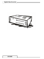
Digital Video Recorder
4CH DVR

Index
Introduction to Digital Video Recorder------------------2
Front panel buttons-----
--------------------------------------3
Rear panel buttons ------------------------------------------4
DVR installation:video output connection--------------5
DVR installation:video input connection----------------5
DVR installation:sensor installation----------------------6
DVR installation:alarm installation---
---------------------7
Power up the unit --------------------------------------------8
On-screen display--------------------------------------------9
Operation guide:Main menu-------------------------------10
Operation guide:Camera select------------
---------------10
Operation guide:Record select------------
----------------11
Operation guide:Record mode----------------------------11
Operation guide:Record frame-rate-----------
-----------12
Operation guide:Video quality-----------------------------13
Operation guide:Record schedule---------------
---------14
Operation guide:Sub menu-password change--------15
Operation guide:Sub menu-time set---------------------16
Operation guide:Sub menu-display format-------------16
Operation guide:Sequential time--------------------------17
Operation guide:HDD setup -------------------------------17
Operation guide:Sensor setup ----------------------------18
Operation guide: How to start Motion detection
recording------------------------------------------------------19
Operation guide:Playback -------
---------------------------20
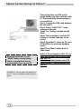
Optional functions:Backup via USB port-----------21
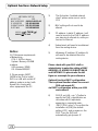
Optional functions:Networking setup--------------------22
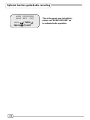
Optional functions:Audio recording setup--------------23
Appendix I Regulatory --------------------------------------24
Appendix II PC viewer application-----------------------25
Appendix III PC client application------------------------27

Introduction
Introduction to Digital Video Recorder (DVR)
The digital video recorder (DVR) is for recording/retrieving video streams
from up to 4 channels at the same time. It adopts a digital image
compression technology to compress the input channel video streams,
and uses HDD to record the compressed video stream.
The following operation guide explains how to operate/manage the DVR,
and the following installation guide explains how to install DVR at your
home or HDD into the DVR.
Hope you enjoy it, use it to protect your home, and eventually make your
home as SAFE HOME.
2

3
4
11
8
9
10
15
14
13
12
2
1
5
6
7
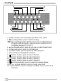
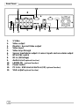
Front Panel
1. (Menu) button: press to display Operation menu option
2. z(Recording button): press to start recording.
3. (Stop recording/playback button):press stop recording/playback
(the authorized password is requested upon stopping record;
the default password is 111111)
4. (Fast forward button): press to play the recorded stream faster.
5. f (Playback button): press to start playback
6. (Pause button): press to pause the video playback
7. Reverse:press to playback backward
8. Channel 1 button: press to select channel 1
9. Channel 2 button: press to select channel 2
10. Channel 3 button: press to select channel 3
11. Channel 4 button: press to select channel 4
12. 田 All channels button: press to select all channels display
13,14. up down buttons: press to change menu field
15. (Select) button: press to change the setting value or enter into a
sub menu
3

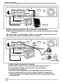
Rear Panel
12
4
3
6
7
911
5
10
8
12
13
1. S Video
2. Video output
3. Monitor : Second Video output
4. Video input
5. Video loop-through
6. Sensor input/alarm output: 4 sensor inputs and one alarm output
7. NTSC/PAL switch
8. DC-in (12Voltage)
9. Audio-in/out
(optional function)
10. LAN(RJ45) (optional function)
11. Power switch
12. PC Link : USB device interface (2.0)
(optional function)
13. VGA output (optional function)
4

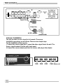
DVR Installation
1.Video output connection ( TV or monitor, LCD monitor)
Please connect TV(monitor) or LCD monitor (optional) to the unit over the Video output
connector.
The unit provides 1 x S-Video input, 2 x BNC connector and 1 x VGA output.
(optional)
The above Figure shows the video signal line connection.
BNC connection
S-Video connection
Or through
BNC connection
Or through
AC/DC adaptor
power outlet
Camera
Signal Line
Power line
S-Video connection
2. Video input connection ( Camera)
Please connect Camera to the unit over the Video input connector.
The unit provides 4 x BNC connectors.The camera installation
Procedures are as following:
i. Connect the video signal line: connect the video signal line to the unit
ii.Connect camera power line: Connect camera’s adaptor to camera, and
plug in the adaptor. The complete connection with a camera will be shown
as figure above:
(Optional)
5

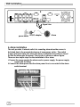
DVR Installation
power outlet
AC/DC adaptor
Sensor
Power line
Signal Line
3.Sensor Installation
The unit provides 4 sensor input for 4 channels. The sensor
Installation procedures are as follows. There are two simple steps
For the installation of the sensors.
i. Connect the sensor signal line: Connect the video signal line to the unit. The
Sensor signal terminal is at the unit’s back panel
ii.Connect the sensor adaptor jack into the sensor, and plug in the adaptor.
CH1 CH2 CH3 CH4
Alarm out
6

DVR Installation
Signal Line
AlarmAC/DC adaptor
power outlet
4. Alarm installation
The unit provides 1 internal switch for sounding alarm when the sensor is
Activated due to the unwanted entrance of anonymous visitor. The switch
Is open at normal state, but, when the alarm is activated, the switch is closed
So that the alarm gets the power. The circuitry is shown as above figure.
There are two simple steps for the installation of the alarm
i. Prepare the power supply:the alarm needs a power supply, the power supply
comes with the alarm
ii.Connect the alarm power line:the alarm power line is connected to the alarm
switch terminal.
7

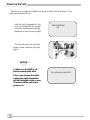
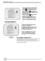
Power up the unit
After the unit is properly installed, the unit is ready to record and play. Then
apply power and switch on.
HDD CHECKING
OK
After the unit is powered on, the
unit is checking HDD for several
seconds, the information will be
displayed on the screen as right:
CH1 CH3
CH3 CH4
The unit will enter into real-time
display mode shown as the right
figure:
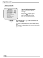
NOTICE
Turn off and on the DVR!
1.
1.
Make sure the HDD is off
Make sure the HDD is off
before removing the drive
before removing the drive
2.Once you resume the initial
2.Once you resume the initial
setting, the right information
setting, the right information
will be displayed on the screen.
will be displayed on the screen.
Then turn off the unit and re
Then turn off the unit and re
-
-
power on it.
power on it.
8

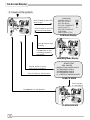
On-Screen Display
MAIN MENU
CAMERA SELECT 1234
RECORD SELECT 1234
RECORD MODE 田
RECORD FRAMERATE 30
VIDEO QUALITY HI
RECORD SCHEDULE
SUB MENU
HARD DRIVE SETUP
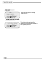
Press button to open OSD
menu as right
SEARCH TIME
HDD: MASTER
04/03/24 13:24:21-04/03/24 13:44:54
>01 TIME 04/03/24 13:24:21
>02 TIME 04/03/24 13:30:55
>03 TIME 04/03/24 13:40:54
(¿À) MOVE,() CHANGE,(f)PLAY
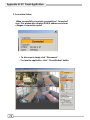
1. Power on the system
CH1 CH3
CH3 CH4
● CH1 ● CH3
● CH3 ● CH4
Press button to exit OSD
menu to real-time display
Pressz button to start
recording
Recording Mode Display
OSD Mode Display
SEARCH MODE
CH1 CH3
CH3 CH4
PLAYBACKMODE
Pressf button to search
time or event to playback
Press button to stop
recording( password is
requested!)
Press button to exit the menu
Press button to stop playback
Press f button
to start playing
9

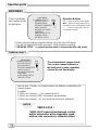
Operation guide
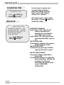
Operation Buttons
---
press to display menu option.
ST--- press to change menu field or
change the unit’s configuration values.
--- press to select menu item or
confirm the selection.
Press to display
menu option shown
as right figure.
MAIN MENU
CAMERA SELECT
¾Please stop recording or playback before you enter into OSD menu.
¾You will be requested to enter password, while stopping recording.
¾
”NETWORK SETUP” is optional function which is only provided with LAN model.
MAIN MENU
¾ CAMERA SELECT 1234
RECORD SELECT 1234
RECORD MODE 田
RECORD FRAMERATE 30
VIDEO QUALITY HI
RECORD SCHEDULE
SUB MENU
HARD DRIVE SETUP
SENSOR SETUP
NETWORK SETUP
MAIN MENU
¾ CAMERA SELECT 1234
RECORD SELECT 1234
RECORD MODE 田
RECORD FRAMERATE 30
VIDEO QUALITY HI
RECORD SCHEDULE
SUB MENU
HARD DRIVE SETUP
SENSOR SETUP
The unit provides 4 camera inputs.
You can use channel buttons on
the front panel to select specified
channel for real-time display.
You can use “” button or channel buttons for different combinations for
channel display.
Example:
1. When you choose (----), all cameras are off
2. When you choose (1234), all cameras are displayed.
3. When you choose (---4), only the fourth channel is displayed.
NOTICE
VIDEO LOSS !
“VIDEO LOSS” signal will be displayed, and the
built-in alarm buzzer will be triggered to sound,
while no video connection or connection failure.
10

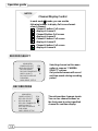
Operation guide
NOTICE
Channel Display Control
In each mode(回) mode, you can use the
following buttons to display Full-screen format
of each channel.
Channel 1 button: Full screen
display of channel 1
Channel2 button: Full screen
display of channel 2
Channel 4 button: Full screen
display of channel 4
Channel 3 button: Full screen
display of channel 3
RECORD SELECT
MAIN MENU
CAMERA SELECT 1234
¾RECORD SELECT 1234
RECORD MODE 田
RECORD FRAMERATE 30
VIDEO QUALITY HI
RECORD SCHEDULE
SUB MENU
HARD DRIVE SETUP
Selecting channel on this menu
option is same as “CAMERA
SELECT” options.
Only selected camera will record
real-time events during recording
period
RECORD MODE
MAIN MENU
CAMERA SELECT 1234
RECORD SELECT 1234
¾ RECORD MODE 田
RECORD FRAMERATE 30
VIDEO QUALITY HI
RECORD SCHEDULE
SUB MENU
HARD DRIVE SETUP
The unit provides 4 camera inputs.
You can use channel buttons on
the front panel to select specified
channel for real-time display.
11

Operation guide
There are two kinds of recording
mode : 回(each mode; full screen
mode)&田 (quad screen mode).
when you set to 回mode, you can
view the full-screen display of one
specified channel.
When you set to 田 mode, quad-
screen will be displayed.
Please use ¿À buttons of front
panel to select mode and then
MAIN MENU
CAMERA SELECT 1234
RECORD SELECT 1234
RECORD MODE 田
RECORD FRAMERATE 30
VIDEO QUALITY HI
RECORD SCHEDULE
SUB MENU
HARD DRIVE SETUP
SENSOR SETUP
enter to confirm the selection
RECORD FRAMRATE
There are 9 different frame rate
settings for operation:
(30fps,15fps,10fps,7fps,5fps,4fps,3
fps,2fps,1fps; But the unit is set
to 30fps in the factory )
Please use ¿À buttons of front
panel to select mode and then
enter to confirm the selection
NOTICE
RECORDING FRAME RATE
The higher the record frame rate is, the more natural look
will be displayed on the screen on playback mode.
But the lower the record frame rate is, the more you can
save the space on HDD.
12
MAIN MENU
CAMERA SELECT 1234
RECORD SELECT 1234
RECORD MODE 田
¾ RECORD FRAMERATE 30
VIDEO QUALITY HI
RECORD SCHEDULE
SUB MENU
HARD DRIVE SETUP
SENSOR SETUP

Operation guide
VIDEO QUALITY
MAIN MENU
CAMERA SELECT 1234
RECORD SELECT 1234
RECORD MODE 田
RECORD FRAMERATE 30
¾ VIDEO QUALITY HI
RECORD SCHEDULE
SUB MENU
HARD DRIVE SETUP
SENSOR SETUP
There are 3 different video quality
settings for operation: Normal,
Low, High
Please use ¿À buttons of front
panel to select mode and then
enter to confirm the selection
NOTICE
DIFFERENT VIDEO QUALITY SETTINGS ON
HDD CAPACITY
The higher the video quality is, the clearer images the unit
plays.
But the lower the video quality is, the more you can save the
space on HDD.
13

Operation guide
RECORD SCHEDULE
MAIN MENU
CAMERA SELECT 1234
RECORD SELECT 1234
RECORD MODE 田
RECORD FRAMERATE 30
VIDEO QUALITY HI
¾RECORD SCHEDULE
SUB MENU
HARD DRIVE SETUP
SENSOR SETUP
Enter into this option to change a
recording schedule during a day
(24-hour period) .
PROGRAMMED RECORD
+ T T T S S T T T T T T T T T +
0 3 6 9 12 15 18 21 24
PRESS (
¿À), THEN ( )
PRESS() TO EXIT
Numbers above indicate the time duration
of 24 hours.
(T) Letter indicates recording.
(S) Letter indicates sensor recording. It
means the unit starts recording as the
attached sensors being triggered during this
period.
(--) Recording is off during this duration.
SETTING EXAMPLE:
0:00 ~ 7:00 SENSOR RECORDING
7:00 ~11:00 RECORDING DISABLED
11:00 ~18:00 RECORDING
18:00 ~24:00 SENSOR RECORDING
+ S S S S S S ----T T T T T T T S S S S S S +
: : : : :
0 6 11 18 24
NOTICE
SENSOR RECORDING INSTALLATION
The unit provides 4 alarm inputs which can be
configured as normal close, normal open, motion
detection +NC and motion detection+NO over
“SENSOR SETUP” menu option. (Please refer to P. 18
for the sensor setup). After the sensor configuration,
please go back to “ RECORD SCHEDULE” menu to
enable sensor recording.
14

Operation guide
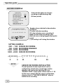
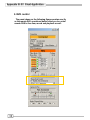
SUB MENU
SUB MENU
¾PASSWORD CHANGE
TIME SET
DATE DISPLAY FORMAT
SEQUENTIAL TIME
PRESS (¿À), THEN ( )
PRESS() TO EXIT
Enter into this option to change
password, time /date setting, date
format and enable the connection
between the unit and PC over
USB interface.
PASSWORD CHANGE .
You enter into “PASSWORD CHANGE”, a
password change input menu replaces the
“SUB MENU” (The default password is
111111)
When the new password is accepted, the
board will flash the following screen
message:
PASSWORD changed!!!
The message will blink 5 times. Then the
display goes back to SUB MENU.
If the password was not accepted, the unit
will automatically return to SUB MENU.
PASSWORD CHANGE
CURRENT PASSWORD: -------
NEW PASSWORD:-------
PASSWORD CONFIRM:--------
PRESS (
¿À), THEN ( )
PRESS() TO EXIT
NOTICE
FRONT PANEL BUTTONS DEFINITION
means “1” 田 means “5” fmeans“b”
means “2” z means “6” means “C”
means “3” means “7” means “D”
means “8” means “E”
means “4” means “9” means “F”
means “0”
15

Operation guide
TIME SET
Enter into this option to change
date and hour.
TIME
2004/03/21 03:23:21
PRESS (¿À), THEN ( )
PRESS() TO EXIT
DATE DISPLAY FORMAT
PRESS (¿À), THEN ( )
PRESS() TO EXIT
DATE DISPLAY FORMAT
The unit provides yyyy/mm/dd or
dd/mm/yyyy variant which depends on
the regional preference.
16

Operation guide
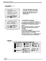
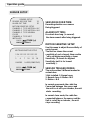
HDD SETUP
Use this menu to specify each
channel display dwell time.
Dwell time settings determine
from 1 sec to 9 sec between
displays for 4 channels.
Note: Please press “” to confirm
the setting. Or press”田“button to
disable the setting.
SEQUENTIAL TIME
SEQUENTIAL TIME
PRESS (¿À), THEN ( )
PRESS() TO EXIT
OVERWRITE ENABLED:
If you choose “YES”, the unit will
continue recording and
overwrite the recorded data
when HDD’s space is full
If you choose “NO”, the unit will stop
recording while HDD’s space is
full
MASTER HDD SIZE:
It indicates the capacity of the primary
HDD installed in the unit
MASTER HDD USED:
It indicates how percentage of HDD’s
capacity has been occupied.
MASTER HDD FORMAT:
It erases all of the recorded data in
Master HDD
The authorized password is requested
before formatting, after the unit
formatted, the following
information will appear on the
screen “HARD DISK
FORMATTED” .
HARD DRIVE SETUP
OVERWRITE ENABLED YES
MASTER HDD SIZE 40000MB
MASTER HDD USED 0MB 0%
MASTER HDD FORMAT
SLAVE HDD SIZE
PRESS (¿À), THEN ( )
PRESS() TO EXIT
17

Operation guide
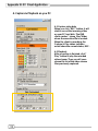
SENSOR SETUP
SENSOR RECORD TIME:
Recording duration once sensor
Being triggered.
ALARM OUT TIME:
It controls how long ( in second)
the alarm sounds after being triggered.
MOTION SENSITIVE SETUP
Use this menu to adjust the sensitivity of
each channel.
The first bar shows the current
sensitivity of each channel, then use the
“” to set higher sensitivity or lower
Sensitivity. ( 0 stands for highest
Sensitivity, but 9 is for lowest
sensitivity.) .
SENSOR TRIGGER MODES:
The unit provides 5 different modes for
variant uses:
1.Not installed. 2. Normal open.
3. Normal close. 4. Motion +N-C
5. Motion + N-O
In normal open mode, the cable line
Connected between the sensor and
the unit is cut off by an intruder, the unit
starts recording.
In normal close mode, the cable line
connected between the sensor and the
Unit is cut off by an intruder , the unit
stops recording
SENSOR SETUP
SENSOR RECORD TIME 15
ALARM OUT TIME 20
MOTION SENSITIVE SETUP
CHANNEL-1 TYPE:MOTION + N-C
CHANNEL-2 TYPE:MOTION + N-O
CHANNEL-3 TYPE:NORMAL
CLOSE
CHANNEL-4 TYPE:NOT
INSTALLED
PRESS (¿À), THEN ( )
PRESS() TO EXIT
MOTION SENSITIVE SETUP
2 2 4 2 2 2 2 2 2 2 2 2 2 2 2 2
: : : : : : : : : : : : : : : :
1 4 7 10 13 16
O:MORE 9:LESS(SENSITIVE)
PRESS (¿À), THEN ( )
PRESS() TO EXIT
18

Operation guide
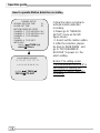
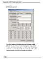
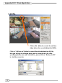
How to operate Motion detection recording
PROGRAMMED RECORD
+ T T T S S T T T T T T T T T +
0 3 6 9 12 15 18 21 24
PRESS (
¿À), THEN ( )
PRESS() TO EXIT
Follow the steps as below to
activate motion-detection
recording.
1.Please go to “SENSOR
SETUP” menu as the left
figure shown.
2. Select out the motion option.
3. After the selection, please
be back to MAIN MENU and
go to “PROGRAMMED
RECORD” to power on the
alarm setting.
Notice: The setting under
“PROGRAMMED RECORD” is
necessary for starting the
operation of motion detection
recording.
SENSOR SETUP
SENSOR RECORD TIME 15
ALARM OUT TIME 20
MOTION SENSITIVE SETUP
CHANNEL-1 TYPE:MOTION + N-C
CHANNEL-2 TYPE:MOTION + N-O
CHANNEL-3 TYPE:NORMAL
CLOSE
CHANNEL-4 TYPE:NOT
INSTALLED
PRESS (¿À), THEN ( )
PRESS() TO EXIT
19
La page est en cours de chargement...
La page est en cours de chargement...
La page est en cours de chargement...
La page est en cours de chargement...
La page est en cours de chargement...
La page est en cours de chargement...
La page est en cours de chargement...
La page est en cours de chargement...
La page est en cours de chargement...
La page est en cours de chargement...
La page est en cours de chargement...
La page est en cours de chargement...
La page est en cours de chargement...
La page est en cours de chargement...
La page est en cours de chargement...
La page est en cours de chargement...
-
 1
1
-
 2
2
-
 3
3
-
 4
4
-
 5
5
-
 6
6
-
 7
7
-
 8
8
-
 9
9
-
 10
10
-
 11
11
-
 12
12
-
 13
13
-
 14
14
-
 15
15
-
 16
16
-
 17
17
-
 18
18
-
 19
19
-
 20
20
-
 21
21
-
 22
22
-
 23
23
-
 24
24
-
 25
25
-
 26
26
-
 27
27
-
 28
28
-
 29
29
-
 30
30
-
 31
31
-
 32
32
-
 33
33
-
 34
34
-
 35
35
-
 36
36


Deltaco DVR Manuel utilisateur
- Catégorie
- Enregistreurs vidéo numériques (DVR)
- Taper
- Manuel utilisateur
dans d''autres langues
- English: Deltaco DVR User manual
Autres documents
-
Lorex L208 Manuel utilisateur
-
Samsung SHR-1041K Manuel utilisateur
-
-
-
Lorex Technology L19WD Series Manuel utilisateur
-
Velleman DVR16H3 Le manuel du propriétaire
-
Maxtor STM3250824AS Manuel utilisateur
-
 GIGAMEDIA GGM DVR Manuel utilisateur
-
Lorex Technology LH3281001 Manuel utilisateur
-
