Sauder Palladia Collection Credenza 412079 Mode d'emploi
- Taper
- Mode d'emploi

NOTE: THIS INSTRUCTION
BOOKLET CONTAINS IMPORTANT
SAFETY INFORMATION.
PLEASE READ AND KEEP FOR
FUTURE REFERENCE.
English pg 1-36
Français pg 37-40
Español pg 41-44
Lot # 372707 05/18/15
Purchased: __________________
Be sure to give us a ring before
making any returns. 1-800-523-3987
Credenza
Palladia Collection | 412079
Need help? Visit Sauder.com to view video assembly tips or chat with a live rep.
Prefer the phone? Call 1-800-523-3987.
Share your journey!
sauder.com
Business or pleasure.
Works both ways.

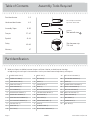
Table of Contents Assembly Tools Required
2-3
4-5
6-36
37-40
41-44
45-46
47
Part Identifi cation
Hardware Identifi cation
Assembly Steps
Français
Español
Safety
Warranty
Hammer
Not actual size
No. 2 Phillips Screwdriver
Tip Shown Actual Size
Skip the power trip.
This time.
412079 www.sauder.com/servicesPage 2
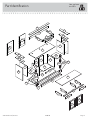
Part Identifi cation
å While not all parts are labeled, some of the parts will have a label or an inked letter on the edge
to help distinguish similar parts from each other. Use this part identifi cation to help identify similar parts.
A OUTER RIGHT END (1)
B OUTER LEFT END (1)
C INNER RIGHT END (1)
D INNER LEFT END (1)
E RIGHT UPRIGHT (1)
F LEFT UPRIGHT (1)
G UPPER RIGHT UPRIGHT (1)
H UPPER LEFT UPRIGHT (1)
I RIGHT PULLOUT UPRIGHT (2)
J LEFT PULLOUT UPRIGHT (2)
K PULLOUT TOP (1)
L RIGHT TOP (1)
M LEFT TOP (1)
N REAR TOP (1)
O BOTTOM (1)
P SHELF (1)
Q UPPER BACK (1)
R BACK (2)
S BOTTOM MOLDING (1)
T CENTER FRONT BRACE (1)
U RIGHT DOOR (1)
V LEFT DOOR (1)
W ADJUSTABLE SHELF (2)
X SKIRT (1)
Y SLIDING SHELF (1)
Z RIGHT FRONT MOLDING (1)
AA LEFT FRONT MOLDING (1)
BB TOP CENTER MOLDING (1)
CC PLINTH (4)
DD CENTER FRONT MOLDING (1)
EE RIGHT TOP MOLDING (1)
FF LEFT TOP MOLDING (1)
M26 VERTICAL MOLDING (2)
HH SHELF MOLDING (1)
II SKIRT BRACE (1)
JJ CENTER BACK (2)
KK HALF DISK (4)

Part Identifi cation
Now you know
our ABCs.
412079www.sauder.com/services
Page 3
A
B
C
D
E
F
G
H
I
I
J
J
K
L
M
N
O
P
Q
R
R
T
U
V
W
W
X
Y
Z
AA
BB
DD
EE
FF
M26
M26
HH
II
JJ
JJ
CC
CC
KK
KK
S

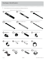
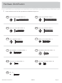
Hardware Identifi cation
å Screws are shown actual size. You may receive extra hardware with your unit.
412079 www.sauder.com/servicesPage 4
FOOT - 1
YY
BBB
FELT DISC CARD - 1
METAL BRACKET - 7
VV
ANGLE BRACKET - 10
UU
TWIST-LOCK®
FASTENER - 26
RR
RUBBER SLEEVE - 8
WW
METAL PIN - 14
XX
CCC
GROMMET - 7
KNOB - 6
AAA
HIDDEN CAM - 12
SS2
CAM DOWEL - 12
TT2
LL
EXTENSION RAIL - 4 EXTENSION SLIDE - 4
MM
40AW
RIGHT CABINET RAIL - 1
40AX
LEFT CABINET RAIL - 1
40AY
RIGHT DRAWER SLIDE - 1
40AZ
LEFT DRAWER SLIDE - 1
(EXTENSION SET SHOWN SEPARATED)
ZZ
HINGE - 4

Hardware Identifi cation
å Screws are shown actual size. You may receive extra hardware with your unit.
412079www.sauder.com/services
Page 5
GGG
BLACK 1-1/8" MACHINE SCREW - 2
EEE
SILVER 1-5/8" MACHINE SCREW - 2
HHH
GOLD 1" MACHINE SCREW - 2
LLL
BLACK 9/16" LARGE HEAD SCREW - 34
FFF
BLACK 1-1/4" FLAT HEAD SCREW - 12
DDD
BLACK 1-7/8" FLAT HEAD SCREW - 24
JJJ
SMALL BROWN 1" FLAT HEAD SCREW - 4
III
BROWN 1" FLAT HEAD SCREW - 12
NNN
GOLD 5/16" FLAT HEAD SCREW - 20
MMM
BLACK 1/2" FLAT HEAD SCREW - 8
OOO
NAIL - 42

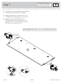
Step 1
Look for this icon. It means a
video assembly tip is available at
www.sauder.com/services/tips
å
Assemble your unit on a carpeted fl oor or on the empty
carton to avoid scratching your unit or the fl oor.
å
To begin assembly, push a SAUDER TWIST-LOCK®
FASTENER (RR) into the large holes in the SHELF (P).
å
Repeat inserting the SAUDER TWIST-LOCK®
FASTENER (RR) into the OUTER ENDS (A and B),
UPRIGHTS (E and F), PULLOUT UPRIGHTS (I and J),
BOTTOM (O), and SLIDING SHELF (Y).
412079 www.sauder.com/servicesPage 6
RR
RR
P
Do not tighten the TWIST-LOCK® FASTENERS in this step.
(26 used)

å
Push twelve HIDDEN CAMS (SS2) into the INNER
ENDS (C and D), PULLOUT UPRIGHTS (I and J), and
UPPER BACK (Q). Then, insert the metal end of a CAM
DOWEL (TT2) into each HIDDEN CAM.
Step 2
412079www.sauder.com/services
Page 7
C
D
I
I
J
J
Q
Arrow
SS2
TT2
(12 used)
Arrow
SS2
TT2
Do not tighten the HIDDEN CAMS in this step.
Insert the metal end of the CAM
DOWEL into the HIDDEN CAM.
Arrow

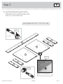
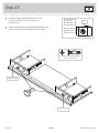
Step 3
å
Separate the EXTENSION SLIDES (MM) from the EXTENSION RAILS (LL)
as shown in the upper diagram below. Be prepared, the parts are greasy.
å
Fasten two EXTENSION RAILS (LL) to the INNER ENDS (C and D). Use
four GOLD 5/16" FLAT HEAD SCREWS (NNN).
å
NOTE: For each EXTENSION RAIL, turn a SCREW into the hole shown in
the enlarged diagram. Then, slide the inner cartridge of the EXTENSION
RAIL out to fi nd the other hole that lines up with the hole in the END. Turn
a SCREW into this hole.
412079 www.sauder.com/servicesPage 8
Push the lever in and pull the SLIDE from the RAIL.
Open end
Open end
LL
LL
LL
MM
C
D
Surface with
HIDDEN CAMS
Surface with
HIDDEN CAMS
GOLD 5/16" FLAT HEAD SCREW
(4 used in this step)
NNN

å
Flip the PULLOUT UPRIGHTS (I and J) over with the
TWIST-LOCK FASTENERS® facing the fl oor and the CAM
DOWELS facing each other.
å
Fasten two EXTENSION SLIDES (MM) to two of the
PULLOUT UPRIGHTS (I and J). Use four GOLD 5/16"
LARGE HEAD SCREWS (NNN) through holes #1 and #3.
å
Repeat this step for the remaining PULLOUT UPRIGHTS (I
and J) and EXTENSION SLIDES (MM).
Step 4
412079www.sauder.com/services
Page 9
I
J
1
1
2
2
3
3
Edge with
TWIST-LOCK®
FASTENERS
Edge with
TWIST-LOCK®
FASTENERS
Open end
Open end
MM
MM
Edge with CAM DOWEL
GOLD 5/16" FLAT HEAD SCREW
(8 used in this step)
NNN

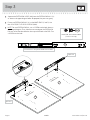
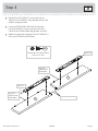
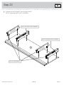
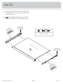
Step 5
å
You have the option to fasten the CABINET RAILS (40AW and 40AX)
to one of three sets of holes in the UPRIGHTS (E and F). Measure
your component that will be sitting on the SLIDING SHELF and
the distance from the CABINET RAIL screw hole to the top of the
UPRIGHT to be sure the component will fi t in your unit.
å
Fasten the CABINET RAILS (40AW and 40AX) to the UPRIGHTS (E
and F). Use four GOLD 5/16" FLAT HEAD SCREWS (NNN).
å
NOTE: The CABINET RAILS are marked "CABINET RIGHT" and
"CABINET LEFT" for easy identifi cation.
412079 www.sauder.com/servicesPage 10
GOLD 5/16" FLAT HEAD SCREW
(4 used in this step)
NNN
Optional CABINET RAIL holes.
E
F
Roller end
Roller end
Edge with
TWIST-LOCK®
FASTENERS
40AW
40AW
40AX
40AX

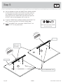
å
Fasten four HALF DISKS (KK) to four PLINTHS (CC). Use
four BROWN 1" FLAT HEAD SCREWS (III).
å
Fasten ten ANGLE BRACKETS (UU) to the OUTER ENDS (A
and B). Use ten BLACK 9/16" LARGE HEAD SCREWS (LLL).
å
NOTE: Be sure the edges of the ANGLE BRACKETS are
even with the edges of the ENDS.
Step 6
412079www.sauder.com/services
Page 11
The larger hole should be facing up
A
B
UU
UU
Surface with
TWIST-LOCK
®
FASTENERS
Surface with
TWIST-LOCK
®
FASTENERS
CC
CC
CC
CC
KK
KK
KK
KK
(10 used)
BLACK 9/16" LARGE HEAD SCREW
(10 used for the ANGLE BRACKETS)
LLL
BROWN 1" FLAT HEAD SCREW
(4 used for the HALF DISKS)
III

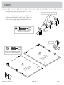
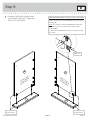
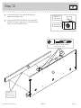
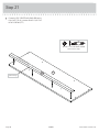
Step 7
å
Fasten the LEFT TOP MOLDING (FF) to the LEFT TOP (M).
Use two BLACK 1-1/4" FLAT HEAD SCREWS (FFF).
å
Fasten the RIGHT TOP MOLDING (EE) to the RIGHT TOP (L).
Use two BLACK 1-1/4" FLAT HEAD SCREWS (FFF).
412079 www.sauder.com/servicesPage 12
Flat edge
Flat edge
Unfi nished surface
Unfi nished surface
Finished surface
Finished surface
EE
M
L
FF
BLACK 1-1/4" FLAT HEAD SCREW
(4 used in this step)
FFF
Flat edge

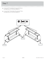
å
Fasten the OUTER ENDS (A and B) to the
TOP MOLDINGS (EE and FF). Tighten four
TWIST-LOCK® FASTENERS.
Step 8
412079www.sauder.com/services
Page 13
EE
FF
A
B
Surface with
TWIST-LOCK
®
FASTENERS
Surface with
TWIST-LOCK
®
FASTENERS
These edges
should be even.
How to use the SAUDER TWIST-LOCK
®
FASTENER
1. Insert the dowel end of the FASTENER into the hole of the
adjoining part.
NOTE: The dowel end of the FASTENER must remain fully
inserted in the hole of the adjoining part while locking
the FASTENER.
2. Tighten the FASTENER with a Phillips screwdriver as tight
as possible.
Dowel end
These edges
should be even.

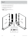
Step 9
å
Fasten two PLINTHS (CC) to the OUTER ENDS (A and B).
Use four BLACK 9/16" LARGE HEAD SCREWS (LLL).
å
Fasten the VERTICAL MOLDINGS (M26) to the OUTER
ENDS (A and B). Use six BLACK 9/16" LARGE
HEAD SCREWS (LLL).
å
NOTE: Make sure the PLINTHS and VERTICAL
MOLDINGS overhang more to the surface of the ENDS
with ANGLE BRACKETS.
412079 www.sauder.com/servicesPage 14
A
B
Surface with
TWIST-LOCK
®
FASTENERS
Surface with
TWIST-LOCK
®
FASTENERS
M26 M26
CC
CC
The VERTICAL MOLDINGS should
be centered over the HALF DISKS.
BLACK 9/16" LARGE HEAD SCREW
(10 used in this step)
LLL

å
Fasten the INNER ENDS (C and D) to the TOP
MOLDINGS (EE and FF). Tighten four HIDDEN CAMS.
Step 10
412079www.sauder.com/services
Page 15
Surface with
HIDDEN CAMS
Surface with
HIDDEN CAMS
Finished edge
C
D
EE
FF
Start Tighten
Arrow
Minimum
190 degrees
Caution
Risk of damage or
injury. HIDDEN CAMS
must be completely
tightened. HIDDEN
CAMS that are not
completely tightened
may loosen, and parts
may separate. To
completely tighten:
Arrow
Maximum
210 degrees

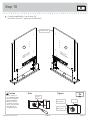
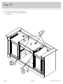
Step 11
å
Fasten the UPPER BACK (Q) and UPPER UPRIGHTS (G
and H) to the SHELF (P). Use eight BLACK 1-7/8" FLAT
HEAD SCREWS (DDD).
412079 www.sauder.com/servicesPage 16
Q
G
H
These holes
must be here.
Surface with
HIDDEN CAMS
P
Surface with
TWIST-LOCK
®
FASTENERS
BLACK 1-7/8" FLAT HEAD SCREW
(8 used in this step)
DDD

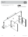
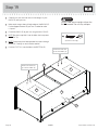
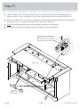
å
Fasten the REAR TOP (N) to the UPPER BACK (Q).
Tighten four HIDDEN CAMS.
å
Fasten the CENTER FRONT BRACE (T) to the UPPER
UPRIGHTS (G and H) and SHELF (P). Use four BLACK
1-7/8" FLAT HEAD SCREWS (DDD).
Step 12
412079www.sauder.com/services
Page 17
N
T
H
P
Q
These holes
must be closer to
the bottom edge.
G
BLACK 1-7/8" FLAT HEAD SCREW
(4 used in this step)
DDD
Arrow
Minimum
190 degrees
Maximum
210 degrees

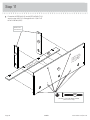
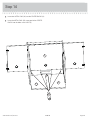
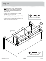
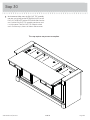
Step 13
å
Fasten the UPRIGHTS (E and F) to the SHELF (P). Tighten
four TWIST-LOCK® FASTENERS.
412079 www.sauder.com/servicesPage 18
Do not stand the unit upright without the
BACK fastened. The unit may collapse.
Caution
E
F
P
Surface with
TWIST-LOCK
®
FASTENERS
Surface
without
TWIST-LOCK
®
FASTENERS

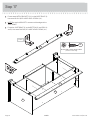
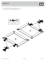
å
Insert four METAL PINS (XX) into the CENTER BACKS (JJ).
å
Insert the METAL PINS (XX) in one end of the CENTER
BACKS into the holes in the SHELF(P).
Step 14
412079www.sauder.com/services
Page 19
XX
JJ
JJ
P
Finished edge

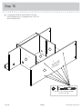
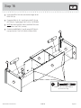
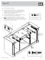
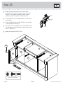
Step 15
å
Fasten the BOTTOM (O) to the UPRIGHTS (E and F)
and CENTER BACKS (JJ). Use eight BLACK 1-7/8" FLAT
HEAD SCREWS (DDD).
412079 www.sauder.com/servicesPage 20
JJ
O
E
F
Surface with
TWIST-LOCK
®
FASTENERS
BLACK 1-7/8" FLAT HEAD SCREW
(8 used in this step)
DDD
La page charge ...
La page charge ...
La page charge ...
La page charge ...
La page charge ...
La page charge ...
La page charge ...
La page charge ...
La page charge ...
La page charge ...
La page charge ...
La page charge ...
La page charge ...
La page charge ...
La page charge ...
La page charge ...
La page charge ...
La page charge ...
La page charge ...
La page charge ...
La page charge ...
La page charge ...
La page charge ...
La page charge ...
La page charge ...
La page charge ...
La page charge ...
La page charge ...
-
 1
1
-
 2
2
-
 3
3
-
 4
4
-
 5
5
-
 6
6
-
 7
7
-
 8
8
-
 9
9
-
 10
10
-
 11
11
-
 12
12
-
 13
13
-
 14
14
-
 15
15
-
 16
16
-
 17
17
-
 18
18
-
 19
19
-
 20
20
-
 21
21
-
 22
22
-
 23
23
-
 24
24
-
 25
25
-
 26
26
-
 27
27
-
 28
28
-
 29
29
-
 30
30
-
 31
31
-
 32
32
-
 33
33
-
 34
34
-
 35
35
-
 36
36
-
 37
37
-
 38
38
-
 39
39
-
 40
40
-
 41
41
-
 42
42
-
 43
43
-
 44
44
-
 45
45
-
 46
46
-
 47
47
-
 48
48


Sauder Palladia Collection Credenza 412079 Mode d'emploi
- Taper
- Mode d'emploi
dans d''autres langues
Documents connexes
-
Sauder Storage Organizer 422647 Mode d'emploi
-
-
-
-
-
-
-
-
-
Autres documents
-
Crafstman CMHT77633 Le manuel du propriétaire
-
Stanley S300 Instructions Manual
-
Stanley Stanley S100 Manuel utilisateur
-
Stanley STHT77404 Manuel utilisateur
-
Stanley Black & Decker S200 Manuel utilisateur
-
-
 Siena Garden P11694 Assembly Instructions
-
 Siena Garden P11695 Assembly Instructions

