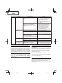
Hikoki CD 36DAL Manuel utilisateur
- Catégorie
- Outils électroportatifs
- Taper
- Manuel utilisateur

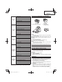
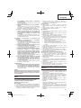
Cordless Grass Trimmer
Akku-Rasentrimmer
Coupe bordure à batterie
Tagliabordi a batteria
Snoerloze graskantenmaaier
Cortaseto a batería
Corta - relva a batería
Read through carefully and understand these instructions before use.
Diese Anleitung vor Benutzung des Werkzeugs sorgfältig durchlesen und verstehen.
Lire soigneusement et bien assimiler ces instructions avant usage.
Prima dell’uso leggere attentamente e comprendere queste instruzioni.
Deze gebruiksaanwijzing s.v.p. voor gebruik zorgvuldig doorlezen.
Leer cuidadosamente y comprender estas instrucciones antes del uso.
Antes de usar, leia com cuidado para assimilar estas instruções.
Handling instructions
Bedienungsanleitung
Mode d’emploi
Istruzioni per l’uso
Gebruiksaanwijzing
Instrucciones de manejo
Instruções de uso
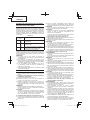
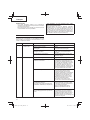
CG 36DL
•
CG 36DL(L)
•
CG 36DAL
•
CG 36DAL(L)
CG36DL
CG36DL(L)
CG36DAL
CG36DAL(L)

2
%
#
&
^
$
*
d
a
s
g
a
f
h
l
k
j
î
Å
Ø
#
∏
∏
Î
Í
7
7
Ï
7
◊ı
Ô
;
Ó
2
1
5
3
4
2
1
8
7
6
1
9
0
HIGH
NOMAL
!
@
q
w
)
e
(
#
u
r
y
t
p
o
i
Ø
#
∏
Å
î
∏
Î
Ó
Ò
Ú
¸
˛
Ç
p
p
;
Ô
˜
Â
Ò
Ú
˝
Â
Í
#
BL36200
1234
5678
9101112
13 14 15 16
17 18 19 20

3
a
v
c
x
z
;
n
c
b
fi
fl
HIGH
NOMAL
Œ
™
¢
£
∞
§
¶
ª
§
¶
b
§
⁄
‹
›
¤
¶
‚
·
·
‚
1.68 mm
2.38 mm
/
,
m
¡
.
c
/
•
150 mm
º
10-15 cm
HIGH
NOMAL
HIGH
NOMAL
!
!
‚
·
·
‚
‡
‡
21 22 23 24
25 26 27 28
29 30 31
32 33 34 35
36 37 38 39

4
10 mm
4 mm
´
‰
Ü
ˇ
Á
ˇ
#
„
b
Ô
40 41 42
43 44 45

5
English Deutsch Français Italiano
1
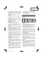
Rechargeable battery Akkumulator Batterie rechargeable Batteria ricaricabile
2
Latch Schnapper Loquet Fermo
3
Battery cover Akkumulatorabdeckung Couvercle de la batterie Coperchio della batteria
4
Terminals Anschlüsse Bornes Terminali
5
Ventilation holes Belüftungslöcher Orifi ces de ventilation Fori di ventilazione
6
Push Drücken Pousser Spingere
7
Insert Einsatz Insérer Inserire
8
Pull out Herausziehen Tirer Estrarre
9
Pilot lamp Kontrollampe Lampe témoin Spia
0
Line Leitung Ligne Linea
!
Power button Einschalttaste Bouton d'alimentation Pulsante di alimentazione
@
Remaining battery
indicator lamp
Ladezustand-
Kontrollleuchte
Témoin lumineux de
puissance batterie résiduelle
Spia luminosa batteria
restante
#
Main pipe Hauptrohr Tuyau principal Tubo principale
$
Housing side Gehäuseseite Côté bâti Lato alloggiamento
%
Loop handle Bügelgriff Poignée Impugnatura ad anello
^
Handle fi xture Griff einbau Fixation pour poignée
Dispositivo di fi ssaggio
dell’impugnatura
&
M6×43 bolts M6×43-Schrauben 43 boulons M6 Bulloni M6×43
*
M6 nuts M6-Muttern Ecrous M6 Dadi M6
(
Handle right Griff rechts Poignée droite Impugnatura destra
)
Lever Hebel Levier Leva
q
Handle left Griff links Poignée gauche Impugnatura sinistra
w
Handle fi xture Griff einbau Fixation de la poignée
Dispositivo di fi ssaggio
dell’impugnatura
e
M5 × 25 hex. Socket bolts
M5 x 25
Innensechskantschrauben
25 x boulons à tête
hexagonale M5
Bulloni con testa esagonale
incassata M5 x 25
r
Locking lever Verriegelungshebel Levier de blocage Leva di bloccaggio
t
Release Lösen Relâcher Rilascio
y
Extend Verlängern Étendre Estensione
u
Holder case Halterungsgehäuse Support du boîtier Scatola di alloggiamento
i
Lock Sperren Verrou Blocco
o
Projection of locking lever
Vorsprung des
Verriegelungshebels
Projection du levier de
verrouillage
Sporgenza della leva di
bloccaggio
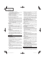
p
Hole Loch Orifi ce Foro
a
Cover Abdeckung Capot Coperchio
s
Knife Messer Lame Coltello
d
D5 tapping screw D5-Blechschraube Vis autotaraudeuse D5 Vite autofi lettante D5
f
Cover bracket Schutzhalter Support du capot Staff a del coperchio
g
M6×25 hex. socket button
bolts
M6×25-Innensechskant-
Rundkopfschrauben
Boulons à tête creuse
hexagonale M6×25
Bulloni con testa esagonale
incassata M6
×
25
h
Cover holder Abdeckungshalterung
Dispositif de retenue du
capot
Supporto del coperchio
j
Flange ass’y Flanschbaueinheit Bride d’assemblage Gruppo fl angia
k
Wing Flügel Ailette Ala
l
Motor case Motorgehäuse Carter de moteur Scatola del motore
;
Hex. bar wrench 4 mm
4-mm-Sechskant-
Inbusschlüssel
Clé à barre hex. de 4mm
Chiave a barra esagonale
da 4 mm

6
English Deutsch Français Italiano
z
Threaded fastener of the
motor case
Schraubgewinde im
Motorgehäuse
Élément de fi xation fi leté
du carter moteur
Dispositivo di fi ssaggio
fi lettato della scatola
motore
x
Hole Loch Trou
Foro
c
Nylon head Nylonkopf Tête du fi l de nylon Testa di nylon
v
Screw (left rotation) Schraube (Linksgewinde)
Vis (rotation vers la
gauche)
Vite (rotazione a sinistra)
b
Nylon line Nylonfaden Fil nylon Filo di nylon
n
Tap Klopfen Tapoter Filettatore
m
Button Knopf Bouton Pulsante
,
Tap/release Tippen/Verlängern Appuyez/Relâchez Tocco/rilascio
.
Wear limit mark (2 marks)
Verschleißgrenzenmarke
(2 Marken)
Marque de limite d'usure
(2 marques)
Contrassegno limite di
usura (2)
/
Extends in 30 mm
increments
Verlängerung à 30 mm
Extensions par segments
de 30 mm
Si estende in incrementi
di 30 mm
¡
Appropriate length 90 –
110 mm
Ungefähre Länge 90 – 110
mm
Longueur appropriée 90
à 110 mm
Lunghezza appropriata
90 – 110 mm
™
Cover Abdeckung Capot Coperchio
£
Case Gehäuse
Châssis
Testina
¢
Hook Haken Crochet Gancio
∞
Press tabs (2 areas)
Drucklaschen
(2 Bereiche)
Appuyez sur les
languettes (2 zones)
Pressione linguette
(2 aree)
§
Reel Rolle Bobine Bobina
¶
Groove Nut Rainure Scanalatura
•
Fold back the middle part
Den mittleren Teil
zurückklappen
Replier la partie centrale Ripiegare la parte centrale
ª
Direction to wind nylon
cord
Wickelrichtung des
Nylonfadens
Direction pour enrouler du
cordon en nylon
Direzione di avvolgimento
cavo di nylon
º
Secure in the stopper Im Stopper sichern Fixez dans l'arrêt Fissare nel tappo
⁄
Stopper Stopper L'arrêt Tappo
¤
Eyelet line guide Fadenführungsöse L'œillet du guide-fi l. Linea guida occhiello
‹
While holding the reel
Während die Rolle
gehalten wird
Tenant la bobine Mentre si tiene la bobina
›
String the line through the
eyelet line guide
Faden durch die
Fadenführungsöse führen
Enfi lez le fi l à travers
l'œillet du guide-fi l.
Inserire il fi lo attraverso la
linea guida dell’occhiello
fi
Locking holes of cover
(2 holes)
Rastlöcher in der
Abdeckung (2 Löcher)
Trous de verrouillage du
couvercle (2 trous)
Fori di bloccaggio del
coperchio (2)
fl
Tabs of case (2 tabs)
Laschen am Gehäuse
(2 Laschen)
Languettes du châssis
(2 languettes)
Linguette testina (2)
‡
Power lamp Betriebsleuchte Témoin d’alimentation Spia di alimentazione
°
Handle Griff Poignée Impugnatura
·
Lock lever Verriegelungshebel Levier de verrouillage Leva di bloccaggio
‚
Lever Hebel Levier Leva
Œ
Speed dial
Geschwindigkeitswählschalter
Cadran des vitesses Regolatore di velocità
„
Projection of locking lever
Verriegelungshebelvorsprung
Projection du levier de
verrouillage
Sporgenza della leva di
bloccaggio
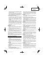
´
Wear limit Verschleißgrenze Limite d’usure Limite di usura
‰
Brush cap Motorsensenaufsatz Bouchon de porte-balai Coperchio della spazzola
ˇ
Nail of carbon brush Klaue der Kohlebürste Clou de balai en carbone
Chiodo di spazzola di
carbone
Á
Protrusion of carbon
brush
Krempe der Kohlebürste Saillie de balai en carbone
Sporgenza di spazzola di
carbone

7
English Deutsch Français Italiano
Ü
Contact portion of brush
tube
Kontaktfl äche des
Bürstenrohrs
Partie de contact du tube
de balai
Parte di contatto del tubo
della spazzola
î
Pull Ziehen Tirer Tirare
Ø
Hanger Hänger Suspension Dispositivo di aggancio
∏
Bracket Bügel Support Staff a
Å
Quick-release belt Schnelllöseriemen
Courroie à déverrouillage
rapide
Cinghia a rilascio rapido
Í
Hook Haken Crochet Gancio
Î
Quick-release bracket Schnelllösebügel
Support à déverrouillage
rapide
Staff a a rilascio rapido
Ï
Press Drücken Appuyer Premere
˝
Release mechanism Lösemechanismus
Mécanisme de
déverrouillage
Meccanismo di rilascio
Ó
Box spanner Steckschlüssel Clé à douilles Chiave a tubo
Ô
Tighten Festziehen Serrer Serrare
Loosen Lockern Desserrer Allentare
Ò
Nut cover Mutterabdeckung Cache écrou Copridado
Ú
Cutting blade Schneideklinge Lame de coupe Lama di taglio
¸
Flange assy Flanschbaueinheit Bride Assieme fl angia
˛
Motor case Motorgehäuse Carter de moteur Scatola del motore
Ç
Cutting blade cover Klingenschutz
Capot de la lame de
coupe
Coprilama
◊
to detach Abnehmen détacher per staccare
ı
to attach Anbringen attacher per fi ssare
Ñ
Left side M10 installation
nut
Linke M10-
Installationsmutter
Écrou d’installation M10
côté gauche
Dado di installazione M10
lato sinistro
Â
Projection of fl ange assy
Vorsprung der
Flanschbaueinheit
Projection de la bride
Sporgenza dell’assieme
fl angia

8
Nederlands Español Português
1
Oplaadbare batterij Batería recargable Bateria de recarregável
2
Vergrendeling Enganche Lingüeta
3
Batterijdeksel Cubierta de batería Tampa da bateria
4
Aansluitpunten Terminales Terminais
5
Ventilatieopeningen Orifi cios de ventilación Orifícios de ventilação
6
Indrukken Empujar Empurrar
7
Insteken Insertar Inserir
8
Uittrekken Sacar Retirar
9
Controlelampje Lámpara piloto Lâmpada piloto
0
Lijn Línea Linha
!
Aan/uit-knop Botón de alimentación Botão de alimentação
@
Indicatielampje
resterende acculading
Indicador luminoso de
batería restante
Luz de indicação da
autonomia da pilha
#
Hoofdpijp Tubo principal Tubo principal
$
Zijkant behuizing Lado de la carcasa Lado da carcaça
%
Lushandvat Empuñadura de bucle Pega de olhal
^
Bevestiging van handvat Soporte de mango Fixador do punho
&
M6×43 bouten Pernos M6x43 Parafusos M6×43
*
M6 moeren tuercas M6 Porcas M6
(
Handvatstang rechts Asidero derecho Pega direita
)
Hendel Palanca Alavanca
q
Handvatstang links Asidero izquierdo Pega esquerda
w
Verbindingsbeugel voor
handvatstangen
Accesorio del asidero Fixador da pega
e
M5 x 25 zeskantige
inbusbouten
25 pernos Allen M5
Parafusos sextavados
interiores M5 x 25
r
Blokkeerhendel Palanca de fi jación Alavanca de bloqueio
t
Ontgrendelen Soltar Libertação
y
Uittrekken Extender Abrir
u
Houderbehuizing Carcasa de soporte Caixa do suporte
i
Vergrendelen Bloquear Bloqueio
o
Uitsteeksel van
blokkeerhendel
Proyección de la palanca
de fi jación
Projecção da alavanca de
bloqueio
p
Gat Orifi cio Orifício
a
Deksel Cubierta Tampa
s
Mes Cuchillo Lâmina
d
D5 tapschroef Tornillo de rosca D5 Parafuso roscante D5
f
Dekselsteun Abrazadera de cubierta Suporte da tampa
g
M6×25 bolkop
inbusbouten
Pernos inferiores de
cabeza hexagonal M6x25
Parafusos M6×25
de cabeça cilíndrica
sextavados
h
Dekselhouder Soporte de cubierta Suporte da tampa
j
Toebehoren van fl ens Conjunto de brida Prato
k
Vleugel Pestaña Asa
l
Motorbehuizing Carcasa de motor Caixa do motor
;
Inbussleutel 4 mm
Llave de barra hexagonal
de 4 mm
Chave hexagonal 4 mm
z
Bevestiging met
schroefdraad voor
motorhuis
Cierre roscado de la
carcasa del motor
Rosca de aperto da caixa
do motor

9
Nederlands Español Português
x
Gaatje Agujero Orifício
c
Nylon kop Cabezal de nailon Cabeça de nylon
v
Schroef (linksdraaiend) Tornillo (giro a izquierdas)
Parafuso (rotação para a
esquerda)
b
Nylondraad Cuerda de nylon Linha de nylon
n
Kloppen Llave Bater
m
Knop Botón Botão
,
Tap/ontgrendeling
Sacar/Liberar Bater/libertar
.
Limietmarkering slijtage (2
markeringen)
Marca de límite de
desgaste (2 marcas)
Marca de limite de
desgaste (2 marcas)
/
Verlengt in stappen van
30 mm
Se extiende en
incrementos de 30 mm
Estende em incrementos
de 30 mm
¡
Geschikte lengte 90 – 110
mm
Longitud apropiada 90 –
110 mm
Comprimento apropriado
90 – 110 mm
™
Deksel Cubierta Tampa
£
Behuizing Carcasa Caixa
¢
Haak Gancho Gancho
∞
Tabs indrukken
(2 gebieden)
Presionar las pestañas
(2 áreas)
Abas de pressão (2 áreas)
§
Spoel Rollo Bobina
¶
Groef Muesca Ranhura
•
Klap het middelste
gedeelte terug
Plegar la parte central Rebater a parte central
ª
Richting voor oprollen
nylondraad
Dirección para el
bobinado el cable de
nailon
Direcção para enrolar o fi o
de nylon
º
Steek de stop er goed in Asegurar en el tapón Fixar no tampão
⁄
Stop Tapón Tampão
¤
Draadgeleidingsoog Guía de la línea del orifi cio Ilhó guia de fi o
‹
Terwijl u de spoel
vasthoudt
Mientras se sujeta el rollo
Enquanto segura na
bobina
›
Steek de lijn door het
draadgeleidingsoog
Haga pasar la línea a
través de la guía de línea
del orifi cio
Passe o fi o pelo ilhó guia
de fi o
fi
Afsluitgaten van kap
(2 gaten)
Agujeros de bloqueo de la
cubierta (2 agujeros)
Orifícios de fi xação da
tampa (2 orifícios)
fl
Tabs van behuizing
(2 tabs)
Pestañas de la carcasa
(2 pestañas)
Abas da caixa (2 abas)
‡
Aan/uit lampje Lámpara de encendido Luz de alimentação
°
Handvat Empuñadura Pega
·
Vergrendelhendel Palanca de bloqueo Alavanca de bloqueio
‚
Hendel Palanca Alavanca
Œ
Snelheidsregelaar Selector de velocidad Selector de velocidade
„
Uitsteeksel van
blokkeerhendel
Proyección de la palanca
de fi jación
Projecção da alavanca de
bloqueio
´
Slijtagegrens Límite de uso Limite de desgaste
‰
Borstelkap Tapa del cepillo Tampa da roçadora
ˇ
Nagel van koolborstel
Uña de escobilla de
carbón
Prego da escova de
carvão
Á
Uitsteeksel van
koolborstel
Saliente de escobilla de
carbón
Saliência da escova de
carvão

10
Nederlands Español Português
Ü
Contactgedeelte van
borstelbuis
Parte de contacto del tubo
de escobilla
Secção de contacto do
tubo da escova
î
Trekken Tirar Puxar
Ø
Hanger Colgador Suporte
∏
Beugel Abrazadera Apoio
Å
Snelontgrendelingsriem
Correa de desenganche
rápido
Alça de libertação rápida
Í
Haak Gancho Gancho
Î
Snelontgrendelingsbeugel
Abrazadera de
desenganche rápido
Suporte de libertação
rápida
Ï
Drukken Presionar Premir
˝
Ontgrendelingsmechanisme
Mecanismo de
desenganche
Mecanismo de libertação
Ó
Pijpsleutel Llave tubular Chave de caixa
Ô
Vastdraaien Apretar Apertar
Losdraaien Afl ojar Desapertar
Ò
Moerafdekking Cubierta de la tuerca Tampa da porca
Ú
Snijmes Cuchilla de corte Lâmina de corte
¸
Flens Ensamble de la brida Conjunto da fl ange
˛
Motorbehuizing Carcasa del motor Caixa do motor
Ç
Afdekking van snijmes
Funda de la cuchilla de
corte
Tampa da lâmina de corte
◊
losmaken para desinstalar para desengatar
ı
bevestigen para instalar para engatar
Ñ
Linker M10
bevestigingsmoer
Tuerca de instalación M10
de lateral izquierdo
Porca de instalação M10
lado esquerdo
Â
Uitsteeksel van fl ens
Proyección de ensamble
de la brida
Projecção do conjunto da
fl ange

11
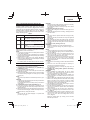
English
(Original instructions)
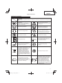
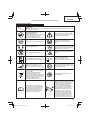
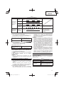
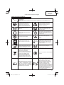
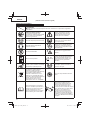
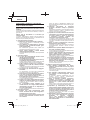
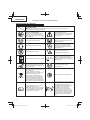
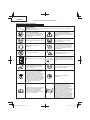
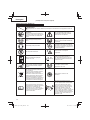
MEANINGS OF SYMBOLS
Symbols
WARNING
The following show symbols used for the machine. Be sure that you understand their meaning before
use.
Read all safety warnings and all
instructions.
Failure to follow the warnings and
instructions may result in electric shock,
fi re and/or serious injury.
Read, understand and follow all
warnings and instructions in this manual
and on the unit.
Always wear eye protection.
Always wear eye, head and ear
protectors when using this unit.
Always wear hearing protection.
Keep all children, bystanders and
helpers 15 m away from the unit. If
anyone approaches you, stop the unit
and cutting attachment immediately.
Do not expose to moisture. Be careful of thrown objects.
Keep bystanders away.
Max
8,000 min
-1
Shows maximum shaft speed. Do not
use the cutting attachment whose max
rpm is below the shaft rpm.
Remove battery before adjusting or
cleaning and before leaving the machine
unattended for any period.
Gloves should be worn when necessary,
e.g., when assembling cutting
equipment.
Only for EU countries
Do not dispose of electric tools together
with household waste material!
In observance of European Directive
2002/96/EC on waste electrical
and electronic equipment and its
implementation in accordance with
national law, electric tools that have
reached the end of their life must be
collected separately and returned to an
environmentally compatible recycling
facility.
Use anti-slip and sturdy footwear.
It is important that you read, fully
understand and observe the following
safety precautions and warnings.
Careless or improper use of the unit may
cause serious or fatal injury.
Blade thrust may occur when the
spinning blade contacts a solid object in
the critical area. A dangerous reaction
may occur causing the entire unit and
operator to be thrust violently. This
reaction is called blade thrust. As a
result, the operator may lose control
of the unit which may cause serious or
fatal injury. Blade thrust is more likely to
occur in areas where it is diffi cult to see
the material to be cut.

12
English
13
17
15
16
14
1212
8
11
10
2
1
9
6
7
5
4
3
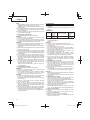
CG36DL
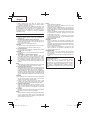
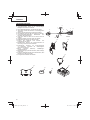
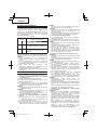
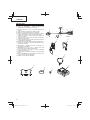
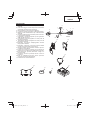
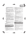
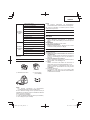
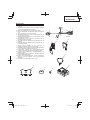
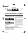
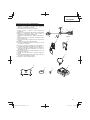
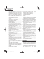
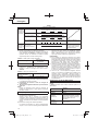
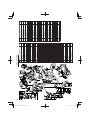
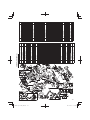
WHAT IS WHAT?
1. Lever: Trigger for activating the unit.
2. Lock lever: Lever that prevents the accidental operation
of the trigger.
3. Motor: Battery-driven, disk-shaped motor.
4. Cover: Protects operator from fl ying debris.
5. Battery: Power source to drive the unit.
6. Power button: Button for switching the units power unit's
power ON or OFF.
7. Speed dial: Dial for adjusting the speed of the motor.
8. Handle right: Handle with lever located on the right side
of the unit.
9. Handle left: Handle located on the left side of the unit.
10. Handle fi xture: Secures the handle to the unit.
11. Hang: Used for attaching a shoulder or hanger belt to the
unit.
12. Shoulder belt: Harness with release mechanism for
combined use with battery.
13. Hanger belt: Harness with release mechanism for
combined use with back pack power supply.
14. Blade (Optional accessories): Metal blade cutting tool.
15. Nut cover (Optional accessories): Holds down the blade.
16. Left side M10 installation nut (Optional accessories):
Secures the blade to the unit.
17. Charger: For charging the battery.

13
English
Carrying power tools with your fi nger on the switch or
energising power tools that have the switch on invites
accidents.
d) Remove any adjusting key or wrench before
turning the power tool on.
A wrench or a key left attached to a rotating part of the
power tool may result in personal injury.
e) Do not overreach. Keep proper footing and
balance at all times.
This enables better control of the power tool in
unexpected situations.
f) Dress properly. Do not wear loose clothing or
jewellery. Keep your hair, clothing and gloves
away from moving parts.
Loose clothes, jewellery or long hair can be caught in
moving parts.
g) If devices are provided for the connection of
dust extraction and collection facilities, ensure
these are connected and properly used.
Use of dust collection can reduce dust related
hazards.
4) Power tool use and care
a) Do not force the power tool. Use the correct
power tool for your application.
The correct power tool will do the job better and safer
at the rate for which it was designed.
b) Do not use the power tool if the switch does not
turn it on and off .
Any power tool that cannot be controlled with the
switch is dangerous and must be repaired.
c) Disconnect the plug from the power source and/
or the battery pack from the power tool before
making any adjustments, changing accessories,
or storing power tools.
Such preventive safety measures reduce the risk of
starting the power tool accidentally.
d) Store idle power tools out of the reach of children
and do not allow persons unfamiliar with the
power tool or these instructions to operate the
power tool.
Power tools are dangerous in the hands of untrained
users.
e) Maintain power tools. Check for misalignment or
binding of moving parts, breakage of parts and
any other condition that may aff ect the power
toolsʼ operation.
If damaged, have the power tool repaired before
use.
Many accidents are caused by poorly maintained
power tools.
f) Keep cutting tools sharp and clean.
Properly maintained cutting tools with sharp cutting
edges are less likely to bind and are easier to control.
g) Use the power tool, accessories and tool bits
etc. in accordance with these instructions,
taking into account the working conditions and
the work to be performed.
Use of the power tool for operations diff erent from
those intended could result in a hazardous situation.
5) Battery tool use and care
a) Recharge only with the charger specifi ed by the
manufacturer.
A charger that is suitable for one type of battery pack
may create a risk of fi re when used with another
battery pack.
b) Use power tools only with specifi cally designated
battery packs.
Use of any other battery packs may create a risk of
injury and fi re.
GENERAL POWER TOOL SAFETY WARNINGS
WARNING
Read all safety warnings and all instructions.
Failure to follow the warnings and instructions may result in
electric shock, fi re and/or serious injury.
Save all warnings and instructions for future reference.
The term “power tool” in the warnings refers to your mains-
operated (corded) power tool or battery-operated (cordless)
power tool.
1) Work area safety
a) Keep work area clean and well lit.
Cluttered or dark areas invite accidents.
b) Do not operate power tools in explosive
atmospheres, such as in the presence of
fl ammable liquids, gases or dust.
Power tools create sparks which may ignite the dust
or fumes.
c) Keep children and bystanders away while
operating a power tool.
Distractions can cause you to lose control.
2) Electrical safety
a) Power tool plugs must match the outlet.
Never modify the plug in any way.
Do not use any adapter plugs with earthed
(grounded) power tools.
Unmodifi ed plugs and matching outlets will reduce
risk of electric shock.
b) Avoid body contact with earthed or grounded
surfaces, such as pipes, radiators, ranges and
refrigerators.
There is an increased risk of electric shock if your
body is earthed or grounded.
c) Do not expose power tools to rain or wet
conditions.
Water entering a power tool will increase the risk of
electric shock.
d) Do not abuse the cord. Never use the cord for
carrying, pulling or unplugging the power tool.
Keep cord away from heat, oil, sharp edges or
moving parts.
Damaged or entangled cords increase the risk of
electric shock.
e) When operating a power tool outdoors, use an
extension cord suitable for outdoor use.
Use of a cord suitable for outdoor use reduces the
risk of electric shock.
f) If operating a power tool in a damp location
is unavoidable, use a residual current device
(RCD) protected supply.
Use of an RCD reduces the risk of electric shock.
3) Personal safety
a) Stay alert, watch what you are doing and use
common sense when operating a power tool.
Do not use a power tool while you are tired
or under the infl uence of drugs, alcohol or
medication.
A moment of inattention while operating power tools
may result in serious personal injury.
b) Use personal protective equipment. Always
wear eye protection.
Protective equipment such as dust mask, non-skid
safety shoes, hard hat, or hearing protection used for
appropriate conditions will reduce personal injuries.
c) Prevent unintentional starting. Ensure the
switch is in the off position before connecting to
power source and/or battery pack, picking up or
carrying the tool.

14
English
c) When battery pack is not in use, keep it away
from other metal objects like paper clips, coins,
keys, nails, screws, or other small metal objects
that can make a connection from one terminal to
another.
Shorting the battery terminals together may cause
burns or a fi re.
d) Under abusive conditions, liquid may be ejected
from the battery; avoid contact. If contact
accidentally occurs, fl ush with water. If liquid
contacts eyes, additionally seek medical help.
Liquid ejected from the battery may cause irritation or
burns.
6) Service
a) Have your power tool serviced by a qualifi ed
repair person using only identical replacement
parts.
This will ensure that the safety of the power tool is
maintained.
PRECAUTION
Keep children and infi rm persons away.
When not in use, tools should be stored out of reach of
children and infi rm persons.
GRASS TRIMMER SAFETY WARNINGS
IMPORTANT
READ CAREFULLY BEFORE USE
KEEP FOR FUTURE REFERENCE
Safe operation practices
● Training
a) Read the instructions carefully. Be familiar with the
controls and the proper use of the machine.
b) Never allow people unfamiliar with these instructions
or children to use the machine. Local regulations can
restrict the age of the operator.
c) Keep in mind that the operator or user is responsible for
accidents or hazards occurring to other people or their
property.
● Preparation
a) Never operate the machine while people, especially
children, or pets are nearby.
b) Wear eye protection, gloves and stout shoes at all times
while operating the machine.
● Operation
a) Use the machine only in daylight or good artifi cial light.
b) Never operate the machine with damaged cover or
without cover in place.
c) Switch on the motor only when the hands and feet are
away from the cutting means.
d) Always disconnect the machine from the power supply
(i.e. remove the plug from the mains or remove the
disabling device)
– whenever leaving the machine unattended;
– before clearing a blockage;
– before checking, cleaning or working on the machine;
– after striking a foreign object;
– whenever the machine starts vibrating abnormally.
e) Take care against injury to feet and hands from the
cutting means.
f) Always ensure that the ventilation openings are kept
clear of debris.
g) Never modify the unit/machine in any way. Do not use
your unit/machine for any job except that for which it is
intended.
● Maintenance, transport and storage
a) Disconnect the machine from the power supply (i.e.
remove the plug from the mains or remove the disabling
device) before carrying out maintenance or cleaning
work.
b) Use only the manufacturer’s recommended
replacement parts and accessories.
c) Inspect and maintain the machine regularly. Have the
machine repaired only by an authorized repairer.
d) When not in use, store the machine out of the reach of
children.
e) When transporting in a vehicle or storage, cover blade
with blade cover.
PRECAUTIONS FOR CORDLESS GRASS
TRIMMER
WARNING
1. Exercise patience in all work with the tool. And dress
properly to keep warm.
2. Plan all work ahead to prevent accidents.
3. Do not operate the tool at night or under bad weather
conditions when visibility is poor. And do not operate the
tool when it is raining or right after it has been raining.
Working on slippery ground could lead to an accident if
you lose your balance.
4. Inspect the nylon head before starting work.
Do not use the tool if the nylon head is cracked, scarred
or bent.
Make sure the nylon head is properly attached. A nylon
head that falls apart or comes loose during operation
could cause an accident.
5. Be sure to attach the cover before starting work.
Operating the tool without this parts could lead to injury.
6. Be sure to attach the loop handle before starting work.
Make sure it is not loose but properly attached before
starting work. Hold the loop handle fi rmly during work and
do not swing the tool around, but use the correct posture
and maintain your balance.
Losing your balance during work could lead to an injury.
7. Take care when starting the motor.
Place the tool on level ground.
Do not operate the tool within 15 m of people or animals.
Make sure that the nylon head does not come into
contact with the ground or trees and plants.
A careless start could lead to injury.
8. Do not secure the lock lever.
Accidentally pulling back the lever could lead to
unexpected injury.
9. Before leaving the tool, press the power button to turn it
off .
10. Operate the tool with care near electric cables, gas pipes
and similar installations.
11. Look out for and remove empty cans, wire, stones or
other obstacles before starting work. And do not work
near tree roots or rocks.
Working in such areas could damage the nylon head or
lead to injury.
12. Never touch the nylon head during operation.
Also make sure it does not come into contact with your
hair, clothes, etc.
13. In the following situations, turn off the motor and check
that the nylon head has stopped rotating.
To move to another work area.
To remove rubbish or grass that has become stuck in the
tool.
To remove from the work area obstacles or the rubbish,
grass and chips generated by trimming.
To lay down the tool.
Doing this with the nylon head still rotating could lead to
unexpected accidents.

15
English
14. Do not use the tool within 15 m of another person.
When you work with someone else, maintain a distance
of more than 15 m.
Flying chips could lead to unexpected accidents.
When working on unstable surfaces like slopes, make
sure that your co-worker is not exposed to any hazards.
Use whistles or other means for calling the attention of
your co-workers.
15. When grass and other objects become entangled in the
nylon head, turn off the motor and make sure the nylon
head has stopped rotating before removing them.
Removing objects from the nylon head when it is still
rotating will lead to injury.
Continuing operation when foreign matter is stuck in the
nylon head may lead to damage.
16. If the tool is operating poorly and produces strange noise
or vibrations, turn off the motor immediately and ask your
dealer to have it inspected and repaired.
Continued use under these conditions could lead to
injury or tool damage.
17. If you drop or bump the tool, inspect it carefully to check
there is no damage, cracks or deformation.
Using a tool that is damaged, cracked or deformed could
result in injury.
18. Secure the tool during vehicle transport to ensure that it
lies still.
Failure to heed this warning may result in an accident.
19. This product contains a strong permanent magnet in the
motor.
Observe the following precautions regarding adhering of
chips to the tool and the eff ect of the permanent magnet
on electronic devices.
CAUTION
◯ Do not place the tool on a workbench or work area where
metal chips are present.
The chips may adhere to the tool, resulting in injury or
malfunction.
◯ If chips have adhered to the tool, do not touch it. Remove
the chips with a brush.
Failure to do so may result in injury.
◯ If you use a pacemaker or other electronic medical
device, do not operate or approach the tool.
Operation of the electronic device may be aff ected.
◯ Do not use the tool in the vicinity of precision devices
such as cell phones, magnetic cards or electronic
memory media.
Doing so may lead to misoperation, malfunction or loss of
data.
CAUTION
1. Do not turn on the nylon head for cutting objects other
than grass. Do not operate the tool in water puddles and
make sure that soil does not come into contact with the
nylon head.
2. The tool contains precision parts and should not be
dropped, exposed to strong impact or water.
The tool could be damaged or malfunction.
3. When the tool is to be stored after use or be transported,
remove the nylon head.
4. Do not expose the tool to insecticide and other chemicals.
Such chemicals could cause cracking and other damage.
5. Replace warning labels with new labels when they
become diffi cult to recognize or illegible and when they
start to peel.
Ask your dealer to provide the warning labels.
6. Do not touch the motor immediately after use since it may
be very hot.
PRECAUTIONS FOR BATTERY AND CHARGER
1. Always charge the battery at a temperature of 0°C –
40°C. A temperature of less than 0°C will result in over
charging which is dangerous. The battery cannot be
charged at a temperature higher than 40°C.
The most suitable temperature for charging is that of
20°C – 25°C.
2. When one charging is completed, leave the charger for
about 15 minutes before the next charging of battery.
Do not charge more than two batteries consecutively.
3. Do not allow foreign matter to enter the hole for
connecting the rechargeable battery.
4. Do not insert object into the air ventilation slots of the
charger.
Inserting metal objects or infl ammables into the charger
air ventilation slots will result in electrical shock hazard or
damaged charger.
5. Using an exhausted battery will damage the charger.
6. Bring the battery to the shop from which it was purchased
as soon as the post-charging battery life becomes too
short for practical use. Do not dispose of the exhausted
battery.
7. Never disassemble the rechargeable battery and
charger.
8. Never short-circuit the rechargeable battery. Short-
circuiting the battery will cause a great electric current
and overheat. It results in burn or damage to the battery.
9. Do not dispose of the battery in fi re. If the battery is burnt,
it may explode.
CAUTION ON LITHIUM-ION BATTERY
To extend the lifetime, the lithium-ion battery equips with the
protection function to stop the output.
In the cases of 1 to 3 described below, when using this
product, even if you are pulling the switch, the motor may
stop. This is not the trouble but the result of protection
function.
1. When the battery power remaining runs out, the motor
stops.
In such case, charge it up immediately.
2. If the tool is overloaded, the motor may stop. In this
case, release the switch of tool and eliminate causes of
overloading. After that, you can use it again.
3. If the battery is overheated under overload work, the
battery power may stop.
In this case, stop using the battery and let the battery
cool. After that, you can use it again.
Furthermore, please heed the following warning and caution.
WARNING
In order to prevent any battery leakage, heat generation,
smoke emission, explosion and ignition beforehand, please
be sure to heed the following precautions.
1. Make sure that swarf and dust do not collect on the
battery.
◯ During work make sure that swarf and dust do not fall on
the battery.
◯ Make sure that any swarf and dust falling on the power
tool during work do not collect on the battery.
◯ Do not store an unused battery in a location exposed to
swarf and dust.
◯ Before storing a battery, remove any swarf and dust that
may adhere to it and do not store it together with metal
parts (screws, nails, etc.).
2. Do not pierce battery with a sharp object such as a
nail, strike with a hammer, step on, throw or subject the
battery to severe physical shock.
3. Do not use an apparently damaged or deformed battery.

16
English
4. Do not use the battery in reverse polarity.
5. Do not connect directly to an electrical outlets or car
cigarette lighter sockets.
6. Do not use the battery for a purpose other than those
specifi ed.
7. If the battery charging fails to complete even when a
specifi ed recharging time has elapsed, immediately stop
further recharging.
8. Do not put or subject the battery to high temperatures or
high pressure such as into a microwave oven, dryer, or
high pressure container.
9. Keep away from fi re immediately when leakage or foul
odor are detected.
10. Do not use in a location where strong static electricity
generates.
11. If there is battery leakage, foul odor, heat generated,
discolored or deformed, or in any way appears abnormal
during use, recharging or storage, immediately remove it
from the equipment or battery charger, and stop use.
CAUTION
1. If liquid leaking from the battery gets into your eyes, do not
rub your eyes and wash them well with fresh clean water
such as tap water and contact a doctor immediately.
If left untreated, the liquid may cause eye-problems.
2. If liquid leaks onto your skin or clothes, wash well with
clean water such as tap water immediately.
There is a possibility that this can cause skin irritation.
3. If you fi nd rust, foul odor, overheating, discolor,
deformation, and/or other irregularities when using the
battery for the fi rst time, do not use and return it to your
supplier or vendor.
WARNING
If an electrically conductive foreign object enters the terminals
of the lithium ion battery, a short-circuit may occur resulting
in the risk of fi re. Please observe the following matters when
storing the battery.
◯ Do not place electrically conductive cuttings, nails,
steel wire, copper wire or other wire in the storage
case.
◯ Either install the battery in the power tool or store
by securely pressing into the battery cover until the
ventilation holes are concealed to prevent short-
circuits (See Fig. 1).
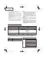
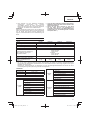
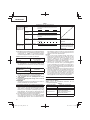
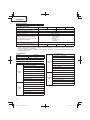
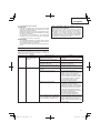
SPECIFICATIONS
POWER TOOL
Model CG36DL CG36DL(L) CG36DAL CG36DAL(L)
Pole type Straight type Extendable type
Cutting capacity diameter 310 mm
Rotation direction Counterclockwise as seen from above
No-load speed 5800 – 7000 min
-1
Operating time on one charge*
(When supplied rechargeable battery is fully
charged)
BSL3620
35 min (Normal)
15 min (High)
BL36200
5.5 h (Normal)
2.5 h (High)
Battery BSL3620: Li-ion 36 V (2.0 Ah 10 cells)
Weight (with nylon head, rechargeable
battery, shoulder belt and cover)
5.7 kg 5.5 kg 6.0 kg 5.8 kg
*
The data in the above table is provided only as an example. Since type of grass, ambient temperature, rechargeable
battery characteristics, work methods, etc. can vary widely the above should only be used as a rough guideline.
Conditions: Outer diameter of nylon head 310 mm, speed dial set to Normal or High. (lever left ON all the time)
CHARGER
Model UC36YRSL
Charging voltage 14.4 V – 36 V
Weight 0.7 kg
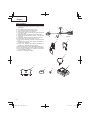
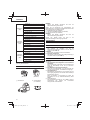
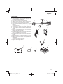
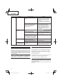
STANDARD ACCESSORIES
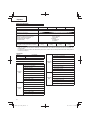
CG36DL
(LBR)
1 Battery (BSL3620) ................................ 1
2 Charger (UC36YRSL) .......................... 1
3 Nylon head ........................................... 1
4 Cover .................................................... 1
5 Hex. bar wrench 4 mm ......................... 1
6 17×19 Combi box wrench..................... 1
7 Protective glass .................................... 1
8 Shoulder belt ........................................ 1
9 Hanger belt ........................................... 1
0 Battery cover ........................................ 1

17
English
CG36DL
(NN)
1 Nylon head ............................................1
2 Cover ....................................................1
3 Hex. bar wrench 4 mm ..........................1
4 17×19 Combi box wrench .....................1
5 Protective glass ....................................1
6 Shoulder belt ........................................1
7 Hanger belt ...........................................1
CG36DL(L)
(LBR)
1 Battery (BSL3620) ................................1
2 Charger (UC36YRSL) ...........................1
3 Nylon head ............................................1
4 Cover ....................................................1
5 Hex. bar wrench 4 mm ..........................1
6 17×19 Combi box wrench .....................1
7 Protective glass ....................................1
8 Shoulder belt ........................................1
9 Hanger belt ...........................................1
0 Battery cover ........................................1
CG36DL(L)
(NN)
1 Nylon head ............................................1
2 Cover ....................................................1
3 Hex. bar wrench 4 mm ..........................1
4 17×19 Combi box wrench .....................1
5 Protective glass ....................................1
6 Shoulder belt ........................................1
7 Hanger belt ...........................................1
CG36DAL
CG36DAL(L)
(LBR)
1 Battery (BSL3620) ................................1
2 Charger (UC36YRSL) ...........................1
3 Nylon head ............................................1
4 Cover ....................................................1
5 Hex. bar wrench 4 mm ..........................1
6 17×19 Combi box wrench .....................1
7 Protective glass ....................................1
8 Shoulder belt ........................................1
9 Hanger belt ...........................................1
0 Battery cover ........................................1
CG36DAL
CG36DAL(L)
(NN)
1 Nylon head ............................................1
2 Cover ....................................................1
3 Hex. bar wrench 4 mm ..........................1
4 17×19 Combi box wrench .....................1
5 Protective glass ....................................1
6 Shoulder belt ........................................1
7 Hanger belt ...........................................1
Standard accessories are subject to change without notice.
OPTIONAL ACCESSORIES (sold separately)
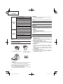
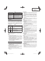
◯ Battery
(BSL3620) (BSL3626)
◯ Back pack power supply ○ Cutting blade
(CG36DL only)
(BL36200)
NOTE
For details of the operations, please see the BL36200
instruction manual.
When using the Cutting blade, have the Nut cover, Left
side M10 installation nut and Counter weight set ready for
installation.
◯ Nut cover (CG36DL only)
◯ Left side M10 installation nut (CG36DL only)
◯ Counter weight set (CG36DL only)
NOTE
For details of the operations, please see the Counter
weight set instruction manual.
Optional accessories are subject to change without notice.
APPLICATIONS
Trimming, scaling and mowing of weed.
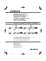
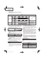
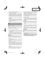
BATTERY REMOVAL/INSTALLATION
1. Battery removal
Hold the housing tightly and push the battery latches to
remove the battery (see Fig. 2).
CAUTION
Never short-circuit the battery.
2. Battery installation
Insert the battery while observing its polarities (see Fig.
2).
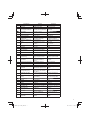
CHARGING
Before using the power tool, charge the battery as follows.
1. Connect the charger’s power cord to a receptacle.
When the power cord is connected, the charger’s pilot
lamp will blink in red. (At 1-second intervals)
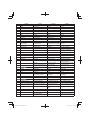
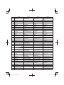
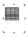
2. Insert the battery into the charger.
Firmly insert the battery into the charger until the line is
visible, as shown in Fig. 3 and 4.
3. Charging
When inserting a battery in the charger, charging will
commence and the pilot lamp will light continuously in
red.
When the battery becomes fully recharged, the pilot lamp
will blink in red. (At 1-second intervals) (See Table 1)

18
English
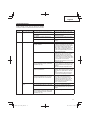
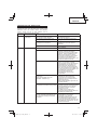
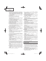
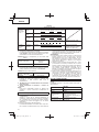
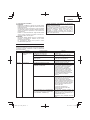
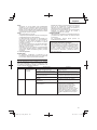
(1) Pilot lamp indication
The indications of the pilot lamp will be as shown in
Table 1, according to the condition of the charger or the
rechargeable battery.
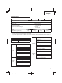
Table 1
Indications of the pilot lamp
The pilot lamp
lights or blinks
in red.
Before
charging
Blinks
Lights for 0.5 seconds. Does not light for 0.5
seconds. (off for 0.5 seconds)
While
charging
Lights
Lights continuously
Charging
complete
Blinks
Lights for 0.5 seconds. Does not light for 0.5
seconds. (off for 0.5 seconds)
Charging
impossible
Flickers
Lights for 0.1 seconds. Does not light for 0.1
seconds. (off for 0.1 seconds)
Malfunction in the
battery or the charger
The pilot lamp
lights in green.
Overheat
standby
Lights
Lights continuously
Battery overheated.
Unable to charge
(Charging will commence
when battery cools).
(2) Regarding the temperatures of the rechargeable battery
The temperatures for rechargeable batteries are as
shown in Table 2, and batteries that have become hot
should be cooled for a while before being recharged.
Table 2 Recharging ranges of batteries
Rechargeable batteries
Temperatures at which the
battery can be recharged
BSL3620 0°C – 50°C
(3) Regarding recharging time
Depending on the combination of the charger and
batteries, the charging time will become as shown in
Table 3.
Table 3 Charging time (At 20°C)
Charger
Battery
UC36YRSL
BSL3620 Approx. 60 min.
NOTE
The charging time may vary according to temperature
and power source voltage.
4. Disconnect the charger’s power cord from the
receptacle.
5. Hold the charger fi rmly and pull out the battery.
NOTE
After operation, pull out batteries from the charger fi rst,
and then keep the batteries properly.
How to make the batteries perform longer
(1) Recharge the batteries before they become completely
exhausted.
When you feel that the power of the tool becomes
weaker, stop using the tool and recharge its battery. If
you continue to use the tool and exhaust the electric
current, the battery may be damaged and its life will
become shorter.
(2) Avoid recharging at high temperatures.
A rechargeable battery will be hot immediately after use.
If such a battery is recharged immediately after use, its
internal chemical substance will deteriorate, and the
battery life will be shortened. Leave the battery and
recharge it after it has cooled for a while.
CAUTION
◯ If the battery is charged while it is heated because it has
been left for a long time in a location subject to direct
sunlight or because the battery has just been used, the
pilot lamp of the charger lights up green. In such a case,
fi rst let the battery cool, then start charging.
◯ When the pilot lamp fl ickers in red (at 0.2-seconds
intervals), check for and take out any foreign objects in
the charger’s battery connector. If there are no foreign
objects, it is probable that the battery or charger is
malfunctioning. Take it to your authorized Service
Center.
◯ Since the built-in micro computer takes about 3
seconds to confi rm that the battery being charged with
UC36YRSL is taken out, wait for a minimum of 3 seconds
before reinserting it to continue charging. If the battery
is reinserted within 3 seconds, the battery may not be
properly charged.
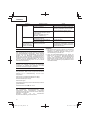
ABOUT POWER LAMP
The power lamp indicates various statuses for the tool.
(Fig. 5)
Table 4 shows the various statuses indicated by the power
lamp.
Table 4
State of lamp Status of Tool
Off Power OFF
Red Power ON
Blinking red
The lever is being pressed while
the overload protection circuit of
the tool is operating.
Quickly blinking red The tool is operating abnormally.

19
English
ABOUT REMAINING BATTERY INDICATOR
When pressing the remaining battery indicator switch, the
remaining battery indicator lamp lights and the battery
remaining power can be checked. (Fig. 5) When releasing
your fi nger from the remaining battery indicator switch, the
remaining battery indicator lamp goes off . The Table 5
shows the state of remaining battery indicator lamp and the
battery remaining power.
Table 5
State of lamp Battery Remaining Power
The battery remaining power is enough.
The battery remaining power is a half.
The battery remaining power is nearly
empty.
Re-charge the battery soonest possible.
As the remaining battery indicator shows somewhat
diff erently depending on ambient temperature and battery
characteristics, read it as a reference.
NOTE
◯ Do not give a strong shock to the switch panel or break it.
It may lead to a trouble.
◯ To save the battery power consumption, the remaining
battery indicator lamp lights while pressing the remaining
battery indicator switch.
◯ When using a back pack power supply (BL36200),
please check the battery level on the battery level display
of the back pack power battery.
For details, please see the BL36200 instruction manual.
PRIOR TO OPERATION
CAUTION
Pull out battery before doing any assembly.
1. Installing the loop handle (Fig. 6) (CG36DL (L),
CG36DAL (L) only)
(1) Remove the M6 × 43 bolts (2 pcs.).
(2) Install the loop handle on the main pipe so that it leans
against the housing.
(3) Place the handle fi xture at the lower end of the main pipe
and secure it fi rmly using M6 × 43 bolts (2 pcs.) and M6
nuts (2 pcs.).
NOTE
Secure the loop handle in a location that provides a good
grip.
CAUTION
Install the loop handle properly and securely as instructed
in the handling instructions.
If not attached properly or securely, it may come off and
cause injury.
2. Installing the bicycle-style handlebars (Fig. 7)
(1) Using the 4 mm hex wrench that is included, remove
the four bolts that have been temporarily secured to the
handle brace (A).
(2) Attach the right-hand side handgrip that has the lever and
the left-hand side handgrip, and then carefully secure the
handle brace (A) using the four bolts.
NOTE
Secure the left and right handgrips in a position that
provides a good grip.
CAUTION
Install the left and right handgrips properly and securely
as instructed in the handling instructions.
If not attached properly or securely, it may come off and
cause injury.
3. Extending the main pipe (Fig. 8)
(1) Release the locking lever to allow the main pipe to be
extended.
(2) Extend the main pipe as far as it will go, making sure that
you hear it click.
NOTE
The motor will not operate unless the main pipe is fully
extended.
When you push the power button, the red power light will
fl ash rapidly.
(3) After extending the main pipe until it clicks, check that
the hole of the holder case is aligned with the hole of the
main pipe and lock the locking lever to fi x the main pipe
securely.
4. Installing cover (See Fig. 9 and 10)
WARNING
Be sure to install the cover in its designated location.
Failure to heed this warning may result in injury from
fl ying stones.
NOTE
Use the supplied hex. bar wrench 4 mm for installation.
(1) Use the supplied D5 tapping screw to install the knife in
the cover. (Fig. 9)
(2) Align the two holes in the cover bracket and the cover
and insert two M6 × 25 hex. socket button bolts. (The
cover bracket is installed in the motor case.)
(3) Place the cover holder on the underside of the cover and
use the supplied hex. bar wrench 4 mm to alternately
tighten the two M6 × 25 hex. socket button bolts until they
are properly tightened.
CAUTION
◯ Take care to avoid cutting yourself on the knife inside the
cover.
◯ Install the cover and knife properly and securely as
instructed in the handling instructions.
If not attached properly or securely, they may come off
and cause injury.
5. Installing the cutting blade (optional accessory)
(CG36DL only)
WARNING
◯ Before installing the cutting blade, be sure to attach
the blade cover, wear thick gloves and take any other
necessary precautions to protect yourself.
◯ Before installing the cutting blade, check carefully and
make sure that it is not cracked, deformed or in any other
way damaged.
◯ When installing the cutting blade, fi rst attach the cutting
blade cover, securing the hole in the middle of the cutting
blade to the fl ange assy projection so that the cutting
blade fi ts into the nut cover and the center part of the
cutting blade does not slip. (See Fig. 20)
◯ After installing the cutting blade, don’t forget to remove
the hex wrench and box spanner.
◯ If the left side M10 installation nut or the nut cover shows
signs of wear or abrasion, replace with a new installation
nut or nut cover.
(1) Insert the fl ange assy into the motor case. At this time,
the wing of the fl ange assy should face the motor case
side. (
Fig. 17)
(2) To install the cutting blade, insert the supplied hex. bar
wrench into the holes in the fl ange assy and the motor
case, and, in order, attach the cutting blade and nut
cover. (Fig. 18)
Install the cutting blade by rotating in the direction
indicated by the arrow.

20
English
NOTE
After tightening securely, adjust so that the left side M10
installation nut can be fastened and loosened.
Failure to do so can cause deformation of the fl ange assy
or baffl e failure.
(3) Position the rounded side of the left side M10 installation
nut so that it faces the box spanner side and then fasten
securely. (Fig. 19)
(4) Check and make sure that the cutting blade has been
properly installed. (Fig. 20)
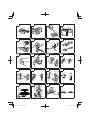
6. Installing the shoulder belt
Use in combination with a BSL3620 battery.
WARNING
◯ Be sure to attach the shoulder belt so that the grass
trimmer can be carried correctly.
◯ If you get the feeling the tool is not operating normally,
turn off the motor immediately, remove the quick-release
bracket of the shoulder belt and remove the tool.
CAUTION
◯ If you do not support the tool when you pull the quick-
release belt, it may fall causing injury or damage.
Hold the main pipe with one hand while you pull with the
other hand.
◯ Make sure the quick-release function operates normally
before you start working.
(1) Place the shoulder belt on the shoulder as shown in Fig.
11 (For use outside of Europe, see Fig. 13) and engage
it with the hanger on the tool. Adjust the shoulder belt to
suitable length.
(2) To remove the tool from the shoulder belt, support the
tool by holding the main pipe with one hand and use the
other hand to pull the quick-release belt as shown in Fig.
11 (For use outside of Europe, see Fig. 13) to free it from
the bracket.
(3) To strap on the tool, insert the bracket in the hook and
insert the quick-release bracket over the hook and into
the wide opening of the bracket. (Fig. 12) (For use
outside of Europe, see Fig. 14)
Gently pull the shoulder belt to make sure that it is
properly attached.
7. Installing the hanger belt
Use in combination with a BL36200 battery.
WARNING
◯ Be sure to attach the hanger belt so that the grass
trimmer can be carried correctly.
◯ If you get the feeling the tool is not operating normally,
turn off the motor immediately, press the release
mechanism of the hanger belt and remove the tool.
CAUTION
◯ If you do not support the tool when you press the release
mechanism, it may fall causing injury or damage.
Hold the main pipe with one hand while you push with
the other hand.
◯ Make sure the release function operates normally
before you start working.
(1) Hook the hanger belt to the BL36200 harness (two
places) as shown in Fig. 15. Then hook the belt to the
hanger of the main pipe (one place). Adjust the hanger
belt to a suitable length.
(2) To detach the tool from the hanger belt, hold the main
pipe with one hand and press the release mechanism of
the hanger belt from both sides as shown in Fig. 16.
To attach the tool, insert from below, making sure that is
it properly attached.
NYLON HEAD
Installation of semi-auto nylon head
1. Function
Automatically feeds more nylon cutting line when it is
tapped.
Specifi cations
Code No.
Type of
attaching
screw
Direction of rotation
Size of
attaching
screw
335234
Female
screw
Counterclockwise
M10×
P1.25-LH
Applicable nylon cord
Cord diameter: Fig. 21
Length: 4 m
CAUTION
◯ The case must be securely attached to the cover.
◯ Check the cover, case and other components for cracks
or other damage.
◯ Check the case and button for wear.
If the wear limit mark on the case is no longer visible or
there is a hole in the bottom of the button, change the
new parts immediately. (Fig. 24)
◯ The nylon head must be securely mounted to the
threaded fastener of the motor case.
◯ For outstanding performance and reliability, always
use Hitachi nylon cutting line. Never use wire or other
materials that could become a dangerous projectile.
◯ If the nylon head does not feed cutting line properly,
check that the nylon line and all components are properly
installed. Contact your Hitachi dealer if you need
assistance.
2. Installation (Fig. 17 and 22)
(1) Insert the fl ange assy into the motor case. At this time,
the wing of the fl ange assy should face the motor case
side. Next, align the holes of the fl ange assy and the
motor case, insert the hex. bar wrench 4 mm, and then
turn to tighten the fl ange assy.
(2) Screw the nylon head directly to the threaded fastener of
the motor case.
The mounting nut of nylon head is left-hand-threaded.
Turn clockwise to loosen/ counterclockwise to tighten.
CAUTION
Install the nylon head properly and securely as instructed
in the handling instructions.
If not attached properly or securely, it may come off and
cause injury.
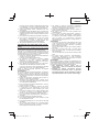
3. Adjustment of line length
Rotate and tap the nylon head on the ground. Nylon line
is drawn out abt, 30 mm by one tapping. (Fig. 23)
Also, you can extend nylon line with hands. This time the
motor must be completely stopped.
Confi rm the line extends in 30 mm increments by
“tapping” and “releasing” the bottom button while pulling
the line ends of the nylon head. (Fig. 24)
◯ Appropriate Length of Nylon Line
The appropriate length of the line when the tool is in use
is 90 – 110 mm. Extend the line to the appropriate length.
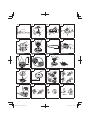
4. Nylon line replacement
(1) Prepare 4m of genuine nylon line in Fig. 21. (Code No.
335235)
(2) Press the opposing tabs, and then remove the cover
from the case. (Fig. 25)
(3) Remove the reel from the case. (Fig. 26)
◯ If there is nylon line remaining, hook the line in the groves,
and then remove the reel.
La page est en cours de chargement...
La page est en cours de chargement...
La page est en cours de chargement...
La page est en cours de chargement...
La page est en cours de chargement...
La page est en cours de chargement...
La page est en cours de chargement...
La page est en cours de chargement...
La page est en cours de chargement...
La page est en cours de chargement...
La page est en cours de chargement...
La page est en cours de chargement...
La page est en cours de chargement...
La page est en cours de chargement...
La page est en cours de chargement...
La page est en cours de chargement...
La page est en cours de chargement...
La page est en cours de chargement...
La page est en cours de chargement...
La page est en cours de chargement...
La page est en cours de chargement...
La page est en cours de chargement...
La page est en cours de chargement...
La page est en cours de chargement...
La page est en cours de chargement...
La page est en cours de chargement...
La page est en cours de chargement...
La page est en cours de chargement...
La page est en cours de chargement...
La page est en cours de chargement...
La page est en cours de chargement...
La page est en cours de chargement...
La page est en cours de chargement...
La page est en cours de chargement...
La page est en cours de chargement...
La page est en cours de chargement...
La page est en cours de chargement...
La page est en cours de chargement...
La page est en cours de chargement...
La page est en cours de chargement...
La page est en cours de chargement...
La page est en cours de chargement...
La page est en cours de chargement...
La page est en cours de chargement...
La page est en cours de chargement...
La page est en cours de chargement...
La page est en cours de chargement...
La page est en cours de chargement...
La page est en cours de chargement...
La page est en cours de chargement...
La page est en cours de chargement...
La page est en cours de chargement...
La page est en cours de chargement...
La page est en cours de chargement...
La page est en cours de chargement...
La page est en cours de chargement...
La page est en cours de chargement...
La page est en cours de chargement...
La page est en cours de chargement...
La page est en cours de chargement...
La page est en cours de chargement...
La page est en cours de chargement...
La page est en cours de chargement...
La page est en cours de chargement...
La page est en cours de chargement...
La page est en cours de chargement...
La page est en cours de chargement...
La page est en cours de chargement...
La page est en cours de chargement...
La page est en cours de chargement...
La page est en cours de chargement...
La page est en cours de chargement...
La page est en cours de chargement...
La page est en cours de chargement...
La page est en cours de chargement...
La page est en cours de chargement...
La page est en cours de chargement...
La page est en cours de chargement...
La page est en cours de chargement...
La page est en cours de chargement...
La page est en cours de chargement...
La page est en cours de chargement...
La page est en cours de chargement...
La page est en cours de chargement...
La page est en cours de chargement...
La page est en cours de chargement...
La page est en cours de chargement...
La page est en cours de chargement...
La page est en cours de chargement...
La page est en cours de chargement...
La page est en cours de chargement...
La page est en cours de chargement...
La page est en cours de chargement...
La page est en cours de chargement...
La page est en cours de chargement...
La page est en cours de chargement...
La page est en cours de chargement...
La page est en cours de chargement...
La page est en cours de chargement...
La page est en cours de chargement...
La page est en cours de chargement...
La page est en cours de chargement...
La page est en cours de chargement...
La page est en cours de chargement...
La page est en cours de chargement...
La page est en cours de chargement...
La page est en cours de chargement...
La page est en cours de chargement...
-
 1
1
-
 2
2
-
 3
3
-
 4
4
-
 5
5
-
 6
6
-
 7
7
-
 8
8
-
 9
9
-
 10
10
-
 11
11
-
 12
12
-
 13
13
-
 14
14
-
 15
15
-
 16
16
-
 17
17
-
 18
18
-
 19
19
-
 20
20
-
 21
21
-
 22
22
-
 23
23
-
 24
24
-
 25
25
-
 26
26
-
 27
27
-
 28
28
-
 29
29
-
 30
30
-
 31
31
-
 32
32
-
 33
33
-
 34
34
-
 35
35
-
 36
36
-
 37
37
-
 38
38
-
 39
39
-
 40
40
-
 41
41
-
 42
42
-
 43
43
-
 44
44
-
 45
45
-
 46
46
-
 47
47
-
 48
48
-
 49
49
-
 50
50
-
 51
51
-
 52
52
-
 53
53
-
 54
54
-
 55
55
-
 56
56
-
 57
57
-
 58
58
-
 59
59
-
 60
60
-
 61
61
-
 62
62
-
 63
63
-
 64
64
-
 65
65
-
 66
66
-
 67
67
-
 68
68
-
 69
69
-
 70
70
-
 71
71
-
 72
72
-
 73
73
-
 74
74
-
 75
75
-
 76
76
-
 77
77
-
 78
78
-
 79
79
-
 80
80
-
 81
81
-
 82
82
-
 83
83
-
 84
84
-
 85
85
-
 86
86
-
 87
87
-
 88
88
-
 89
89
-
 90
90
-
 91
91
-
 92
92
-
 93
93
-
 94
94
-
 95
95
-
 96
96
-
 97
97
-
 98
98
-
 99
99
-
 100
100
-
 101
101
-
 102
102
-
 103
103
-
 104
104
-
 105
105
-
 106
106
-
 107
107
-
 108
108
-
 109
109
-
 110
110
-
 111
111
-
 112
112
-
 113
113
-
 114
114
-
 115
115
-
 116
116
-
 117
117
-
 118
118
-
 119
119
-
 120
120
-
 121
121
-
 122
122
-
 123
123
-
 124
124
-
 125
125
-
 126
126
-
 127
127
-
 128
128


Hikoki CD 36DAL Manuel utilisateur
- Catégorie
- Outils électroportatifs
- Taper
- Manuel utilisateur
dans d''autres langues
- italiano: Hikoki CD 36DAL Manuale utente
- English: Hikoki CD 36DAL User manual
- español: Hikoki CD 36DAL Manual de usuario
- Deutsch: Hikoki CD 36DAL Benutzerhandbuch
- Nederlands: Hikoki CD 36DAL Handleiding
- português: Hikoki CD 36DAL Manual do usuário
Documents connexes
Autres documents
-
Hitachi RB 36DL Handling Instructions Manual
-
Efco BCi 30 Le manuel du propriétaire
-
Perel EFL27 Manuel utilisateur
-
-
-
-
-
-
Dolmar AT3724U Le manuel du propriétaire
-