
1
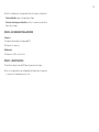
INSTALLATION MANUAL
MANUEL D’INSTALLATION
Electric Vehicle Energy
Management System (EVEMS)
Contrôleur de charge pour véhicules électriques
Manufactured by
Manufacturé par
MAIN POWER SUPPLY
240-208V, Single Phase
60A - 70A - 80A - 90A
100A - 125A - 150A - 200A
ALIMENTATION PRINCIPALE
240-208V, Monophasé
60A - 70A - 80A - 90A
100A - 125A - 150A - 200A
APPROVED MARKET
North America
MARCHÉ AGRÉÉ
Amérique du Nord
MODELS MODÈLES
DCC-12
V5
Read and save these instructions
Lire et garder ces instructions
Designed by
Design par
IFRANÇAISI
IENGLISHI
DCC-12
GENERATION 3 GÉNÉRATION 3
Nema 3R Enclosure
Boitier Nema 3R

2

3
ABOUT THIS MANUAL
ERRORS AND INACURACIES
For any inaccuracy or omission, or to forward any general comments
or suggestions concerning the quality of this manual, please send an
email to [email protected].
COPYRIGHTS AND TRADE NAMES
All information’s in this manual are subject to copyright protection and
other intellectual property protection of THERMOLEC LTÉE. / RECHARGE
VÉHICULE ÉLECTRIQUE and its licensors. This installation manual cannot
be modified, reproduced or copied without a prior written authorisation
from THERMOLEC LTÉE. / RECHARGE VÉHICULE ÉLECTRIQUE and
its licensors. Additional information’s are available on request. The
following logos are trade names or trademarks of THERMOLEC LTÉE. /
RECHARGE VÉHICULE ÉLECTRIQUE in the United States and in Canada.
DCC – EVEMS
All other trade names mentioned in this document are the property of
their respective owners and their uses in this manual does not means
a sponsorship or approval of the product. The use of any trade name
shown in this document is strictly forbidden.
In this document, the terms DCC – EVEMS and DCC are equivalent.
TABLE OF CONTENTS
About This Manual 3
Safety Information 4
Specifications 5
Characteristics 5
Typical installation 6
DCC Installation 7
Application 11
Maintenance 11
Lights Code 11
IENGLISHI

4
SAFETY INFORMATION
This document describes important safety instructions which must be
followed during installation, maintenance and application of the DCC –
Electric Vehicle Energy Management System (EVEMS).
Warning
Read all instructions prior using this
product.
Always disconnect the DCC – EVEMS
power supply before any works.
Use only the DCC – EVEMS by following
the technical specifications indicated in
this installation manual.
Do not install the DCC – EVEMS nearby
inflammable materials, explosives or
fuels, chemical products and vapors.
Never spray the DCC – EVEMS with wa-
ter or any other liquids.
Stop using the DCC – EVEMS imme-
diately if defective, cracked, broken or
damaged.
Never try to modify, repair or dismantle
the DCC – EVEMS. Please contact the
manufacturer for any malfunction.
Never insert a sharp object inside the
DCC – EVEMS at the risk of causing da-
mages to the components.
Any improper use of the DCC – EVEMS
could result in serious injuries which
may cause death.
For a vertical installation on a wall, refer
to the information’s on the enclosure for
the choice of mounting position.
Precautions
Any improper use of the DCC – EVEMS
can cause damages and premature wear
of the components, which voids the war-
ranty.
Never use the DCC – EVEMS above or
below the temperature range of -22°F
to 113°F (-30°C to 45°C).
Only store the DCC – EVEMS above or
below the temperature range of -4°F to
158°F (-20°C to 70°C).
The installation of the DCC – EVEMS
must be done in accordance with the
latest electrical code requirements.
Notes
It is recommended to schedule the
charging of the vehicle during hours of
low electrical consumption to minimize
interruptions to the electric charging
station.
Always check that the DCC – EVEMS is
adequately fixed to the wall or ceiling or
in a location to avoid any damages.
Even if this product is advertised for EV
chargers, it can be installed with other
types of load.
It is the installer’s responsibility to make
sure that the electric power source
is adequate for the use of the DCC –
EVEMS.
Do not use any cleaning solvents to clean
the DCC – EVEMS.
Limited warranty
1 THERMOLEC LTÉE. warrants the inte-
grated controls against any defects for
a period of one year from the shipping
date. The warranty is limited to the
equipment and components supplier
by THERMOLEC LTÉE.
2 In case of incorrect installation, inap-
propriate use or repairs done by unau-
thorized personnel by THERMOLEC
LTÉE., the warranty will be automati-
cally void.
3 THERMOLEC LTÉE. undertakes to repair
or replace, at site or at the manufactu-
ring location, at his option, the defec-
tive material only after an evaluation
made by its representative.
4 THERMOLEC LTÉE. will not be held
liable for damages or delays and will
not be required to pay transport cost
of the EVEMS said to be defective.
5 THERMOLEC LTÉE. shall not be liable
for any indirect damages or delays
caused by faulty workmanship or
materials.
No indemnity will be paid for repairs,
replacements or modifications wit-
hout a prior written consent supplied
by THERMOLEC LTÉE.
6 Any control device or accessory sup-
plied with the DCC – EVEMS to be
installed or connected remotely from
the EVEMS will be guaranteed by the
manufacturer only under the special
conditions mentioned in paragraph 5.
7 The components supplied for repairs
are guaranteed for the remaining of
the warranty on the original product or
90 days. The longest period will pre-
vail.
8 All repairs made at the THERMOLEC
LTÉE. plant are guaranteed for 30 days
from the date of repairs.

5
CHARACTERISTICS
CONDITIONS FOR APPLICATION
The DCC-12 is an Energy Management System specially designed to
allow the connection of an EV Charger, in a house or dwelling, to an
electrical panel that is at full capacity and would otherwise need to have
an expensive service upgrade.
OUTDOOR INSTALLATION
The DCC-12 has a NEMA 3R enclosure approved for indoor and outdoor
installations.
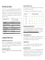
MAIN POWER SUPPLY (CB)
The DCC – Electric Vehicle Energy Management System can be powered
by a 240/208V AC single phase source.
The following options are offered depending on EV charger breaker:
Breaker Main power supply
EV charger 60A 70A 80A 90A 100A 125A 150A 200A
30A
40A
50A
60A
Voltage and wiring 240/208V AC single phase:
L1, L2, Neutral, Ground.
Frequency 50 à 60 Hz
Operation temperature -22°F à 113°F (-30°C à 45°C)
Rated NEMA 3R
Wire Gauge Size up to 250 kcmil (MCM)
Dimensions* (H" x W" x D") 11" x 8" x 5"
Total weight*8 lb (3,63 kg)
*Approximative and can change without notice. V2
SECONDARY LOAD SUPPLY (EVC)
The DCC – EVEMS will provide power to a charging station through a
30A, 40A, 50A or 60A 240/208V AC circuit breaker, L1, L2 and ground.
The DCC-12 is NOT equipped with an internal breaker. The breaker to
protect the branch circuit needs to be provided by the installer.
TRIP PERCENTAGE (TP)
The DCC - EVEMS is factory set to turn off the charging station if the total
consumption of a service exceeds 80%. For a different configuration, see
the "TP" configuration details on page 10 of this manual.
POWER OUTAGE
In the event of a power outage, the DCC – EVEMS automatically restore
the power supply to the vehicle charging station when power returns.
RECOVERY TIME (RT)
Following a power cut to the electric vehicle supply equipment (EVSE),
a 15 minutes delay is initiated to monitor the total consumption of the
electrical power system. Power to the vehicle will then be restored if the
total load consumption is lower than 80% of the main circuit breaker
rating during a period exceeding the 15 minutes’ recovery time.
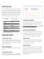
SPECIFICATIONS
The DCC – Electric Vehicle Energy Management System (EVEMS) is a
safety device with programmable controller that can protect an electrical
distribution circuit in relation with its main breaker. It will prevent
overloading the electrical distribution circuit by turning off momentarily
the power to the charging station when the demand exceeds 80% of the
main breaker rating.
Breaker Main power supply
EV charger 60A 70A 80A 90A 100A 125A 150A 200A
30A
40A
50A
60A
Voltage and wiring 240/208V AC single phase:
L1, L2, Neutral, Ground.
Frequency 50 à 60 Hz
Operation temperature -22°F à 113°F (-30°C à 45°C)
Rated NEMA 3R
Wire Gauge Size up to 250 kcmil (MCM)
Dimensions* (H" x W" x D") 11" x 8" x 5"
Total weight*8 lb (3,63 kg)
*Approximative and can change without notice. V2

6
CONTROL BY A THIRD PARTY SYSTEM (EMS)
The DCC control board has a dry contact type input
(black terminal) to be connected to a building energy
management system.
When the contact is:
- Open, the DCC cuts the power to the charging station.
- Closed, the DCC supplies power to the charging station, provided that
the main power supply of the DCC is under the only configured current.
The dry contact type output, which reproduces the state of the dry contact
input, allows several DCCs to be cascaded on a single control signal
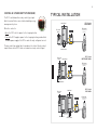
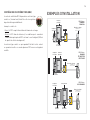
TYPICAL INSTALLATION
DCC-12 with
MAIN PANEL
FOR HOMES
DCC-12 with
METER BOX PANEL
DCC-12 with
SUB PANEL
DCC-12
Current
transformers
Electrical
Meter
Main Panel
EV Charger
compatible with
all models
DCC-12
Electrical
Meter Main Panel
Current
transformers
EV Charger
compatible with
all models
DCC-12
Current
transformers
Sub Panel
Electrical
Meter
Main Panel
EV Charger
compatible with
all models

7
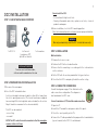
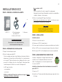
DCC INSTALLATION
STEP 1: CHECK THE PACKAGE CONTENTS
1 x DCC-12 2 x Current
transformer (CT)
(with 25 feet of wire)
1 x Screwdriver
STEP 2: PREPARATIONS FOR INSTALLATION
1. Disconnect the main power
2. Select the DCC intended location.
Select an intended location preferably less than 25 feet away from
the electric panel (power source). The current transformers supplied
have a wiring of 25 feet in length, but can be extended (see the section
Step 4: Conductor connexions for the extension details).
The DCC can be mounted:
- on a ceiling
- on a wall
NOTE: The DCC controller must be mounted so that the nameplate
remains visible at all times.
INSTALLATION VIDEO
To access our installation video,
visit our website www.dccelectric.com
Do not install the DCC:
- In a location with high level of risk.
- Nearby inflammable materials, explosives or fuels, chemical
products and vapors.
3. Before installation, check the DCC mounting position.
Refer to the information on the enclosure to insure proper installation.
WARNING
Warranty automatically void if the DCC is installed incorrectly.
STEP 3: INSTALLATION
Wall installation
1. Remove the 4 cover screws.
2. Position the DCC at the intended location.
3. Ensure that the mounting is according with the information’s
on the enclosure.
4. Fix the DCC with the anchors provided for the type of surface.
5. Check that the DCC is adequately fixed to the wall or ceiling.
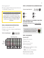
STEP 4: CONDUCTOR CONNEXIONS
Consult the diagram on page 10 for all details on the
cable connections configuration. This diagram is
also found under the DCC cover.
Current transformers (CT) installation and connections
1. Open the CT.
2. Install the CT around the main power cable of the panel.
3. Check the correct polarity on the CTs.
4. Connect the CT cables provided for this purpose to the terminal blocks
(green terminal) on the DCC-12 control board.

8
EXTENSION OF CURRENT TRANSFORMERS’S WIRE
The DCC comes with 25 feet of wire. It is possible
to extend the wiring supplied with the current transformers.
Additional wire must be 300V rated, minimum 18 AWG (1mm),
4 conductors shielded twisted (ex: FT4 SHIELD. 4C FAS #18
or equivalent).
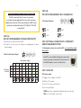
STEP 5A:
DIP SWITCH PROGRAMMING FOR MAIN POWER SUPPLY
1. Identify the set-up section on the DCC.
2. Set up the section as per the layout corresponding to the main
power supply :
Main Circuit Breaker (Amps)
Main power supply
60A 70A 80A 90A 100A 125A 150A 200A
EV Charger
(Breaker)
30A
40A
50A
60A
STEP 5B:
DIP SWITCH PROGRAMMING FOR EV CHARGER (EVC)
EV Charger (Breaker)
30A 50A
40A 60A
STEP 6 (OPTIONAL): CONNECTION TO A THIRD PARTY
ENERGY MANAGEMENT SYSTEM
If a third-party system is to control the DCC, see step 6 at the end of
this manual.
STEP 7: STARTUP
DCC power supply
1. Supply electrical power to the DCC.
2. Wait ten (10) seconds.
3. Check if the relay is switched on.
4. Check the pilot light:
GREEN at all time: compliant installation, go to the next step.
RED: refer to the Lights code section.
If the DCC is not used with a third party system, do not
remove the jumper connecting the two terminals of
the EMS IN input to create a closed contact.

9
Charging station power supply
1. Put the circuit breaker in the ON position.
2. Check if the electric vehicle supply equipment (EVSE) is powered:
EVSE powered: go to the next step.
EVSE not energized: check the charging station connections.
STEP 8: SECURE AND REENERGIZE
Secure
1. Turn off the power on the DCC.
2. Put the cover back.
Re-energize
1. Supply electrical power to the DCC.
STEP 9: IDENTIFICATION
1. Identify the branch circuit breaker.
2. Register all configuration settings of the charging station in the space
provided on the cover.

10
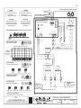
TO INSTALL AROUND THE POWER SUPPLY CABLE
A INSTALLER AUTOUR DES CABLES D’ALIMENTATION DE PANNEAU
LEGEND
R POWER RELAY
DCC ELECTRONIC CONTROLLER
T TRANSFORMER
CT CURRENT TRANSFORMER
IMPORTANT
Wire in accordance with local
and National Electrical codes.
Read instructions carefully before
wiring and operating.
LÉGENDE
R RELAIS DE PUISSANCE
DCC CONTROLEUR ELECTRONIQUE
T TRANSFORMATEUR
CT TRANSFORMATEUR DE COURANT
IMPORTANT
Suivre les codes électriques
nationaux et locaux ainsi que
les instructions contenues
dans l’appareil.
CT
G
R1
R1
R2
R2
CT
DCC ELECTRONIC CONTROLLER
CONTROLEUR ELECTRONIQUE DCC
PB SWITCH
(RESET)
LED
2W 2B 1B1W
Blue / Bleu
White / Blanc
Green / Vert
24V
208 / 240V
TRANSFORMER
TRANSFORMATEUR
POWER RELAY
RELAIS DE PUISSANCE
POWER RELAY
RELAIS DE PUISSANCE
12VA
Yellow / Jaune
Orange / Orange
R1
L1 T1 L2 T2
G
Red / Rouge
Black / Noir
Black / Noir
White / Blanc
Black / Noir
White / Blanc
G
R2
ELECTRIC VEHICLE
CHARGER
BORNE DE RECHARGE
208V / 240V 1PH
ALIMENTATION
DU PANNEAU
208V / 240V 1PH
CURRENT TRANFORMERS
TRANSFORMATEUR
DE COURANT
T
POWER SUPPLY
DRAWING NO. DCC-12 CONTROLLER
DATE
01-28-2020
PER
TITLE
DCC-12 CONTROLLER GEN 3 (G3)
BOITIER DE CONTROLE DCC-12 GEN 3 (G3)
CONFIGURATION DIAGRAMS / DIAGRAMMES DE CONFIGURATION
Trip Percentage (%)
Pourcentage de débarquement (%)
Reintegration Time (Minutes)
Temps de reprise (Minutes)
Trip Delay: 15 seconds (Default)
Temps de débarquement: 15 secondes (Défaut)
EV Charger (Breaker)
Borne de recharge (Disjoncteur)
80% (Default / Défaut)
15 Min (Default / Défaut)
OFFON
Main Circuit Breaker (Amps)
Entrée électrique (Ampérage)
Main power supply / Alimentation principale
60A 70A 80A 90A 100A
125A 150A 200A
30A ✓ ✓ ✓ ✓ ✓ ✓ ✓ ✓
40A ✗ ✗ ✓ ✓ ✓ ✓ ✓ ✓
50A ✗ ✗ ✗ ✗ ✓ ✓ ✓ ✓
60A ✗ ✗ ✗ ✗ ✗ ✓ ✓ ✓
EV Charger
(Breaker) /
Borne de recharge
(Disjoncteur)
Red / Rouge
Black / Noir
THERMOLEC V.7
DCC V.3
IN IL ILOUT
TO NEXT DCC
AU SUIVANT DCC
ENERGY MANAGEMENT SYSTEM
SYSTÈME DE GESTION D’ÉNERGIE
TERMINAL
Black / Noir
TERMINAL
Green / Vert
30A DCC-12-30A 40A DCC-12-40A 50A DCC-12-50A 60A DCC-12-60A
60% 70% 80%

11
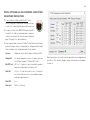
LIGHTS CODE
Green The charging station is energized.
Green The charging station is energized. The total
load exceeds 80%. If the loads exceed 80% for
a predetermined period, the charging station
will be de-energized.
Yellow The charging station is not energized. The total
loads exceed 80%. The resumption time will
start when the total load is lower than 80%.
Yellow The charging station is not energized. The total
load is lower than 80% and the recovery time is
in progress. Each flash mean two (2) minutes
before the resumption of power to the charging
station. (ex: 3 flashes = 6 minutes before power
to the charging station). During that period, if
the total load exceeds 80%, the recovery time
will restart from the beginning.
Red Malfunction:
1. Check all connections and voltage.
2. Check the DIP switch configuration settings.
3. Check if the current transformers (CT) are
properly connected and interlocked.
4. Check if the connection for the current
transformers are properly connected to the
PCB electronics.
5. If the problem persists, send pictures of the
installation at [email protected]a and then call
1 (833) 717-1355.
OFF No power. Check the power source.
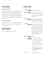
APPLICATION
Electric vehicle recovery time
Following a power cut to the electric vehicle supply equipment (EVSE), a 15
minutes delay is initiated to monitor the total consumption of the electrical
system. Power to the vehicle will then be restored if the power required
by the total of the loads is less than 80% of the main circuit breaker and if
the control input for the energy management system is in the closed state
(closed contact).
Electric vehicle charging time
It is recommended to schedule the charging vehicle program during
hours of low electrical consumption to minimize interruptions to the
electric charging station.
MAINTENANCE
Do not use any cleaning solvents to clean the DCC.

12
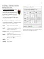
STEP 6 (OPTIONAL): CONNECTION TO A THIRD PARTY
ENERGY MANAGEMENT SYSTEM
1. If a third-party system is to control the DCC, connect
the "EMS IN" input (black terminal) to the "dry contact"
output of the third-party energy management system.
2. If required, connect the output (EMS OUT) to the next
DCC to be controlled. The recommended cable for the
control signal is a twisted copper pair, 18 gauge minimum
and 14 gauge if multi-stranded.
3. For the Cristal Controls LS-100 control panel (external power
management system recommended), the configuration on the Outputs
tab of the configuration software should be as follows:
Cycling Number of outputs used to control DCCs.
Load kW The maximum load associated with each LS-100
output (e.g., 7.7 kW per DCC-9-40)
Min OFF (sec) 900 sec. This is the minimum amount of time a
charger must remain off.
Delay ON 300 sec. This is the time between the successive
activation of two outputs and corresponds to the
start-up time of the charger.
Delay OFF 2 sec.
Cycle delay 7200 sec (2 hours)
For questions about other LS-100 system configuration settings, see
www.cristalcontrols.com/en/support-and-resources/

13
À PROPOS DE CE MANUEL
ERREURS ET MANQUE DE PRÉCISION
Pour communiquer toute inexactitude ou omission, ou afin de fournir
des commentaires généraux ou des suggestions quant à la qualité de
ce manuel, veuillez envoyer un courriel à soutien@rve.ca.
DROITS D’AUTEUR ET MARQUES DE COMMERCE
Toutes les informations contenues dans ce document sont soumises
aux droits d’auteur et aux autres droits de propriété intellectuelle
de THERMOLEC LTÉE. / RECHARGE VÉHICULE ÉLECTRIQUE et ses
concédants de licence. Ce manuel d’installation ne peut pas être modifié,
reproduit ou copié, en tout ou en partie, sans l’autorisation écrite
préalable de THERMOLEC LTÉE. / RECHARGE VÉHICULE ÉLECTRIQUE
et ses concédants de licence. Des informations supplémentaires sont
disponibles sur demande. Les éléments suivants sont des marques
commerciales ou des marques déposées de THERMOLEC LTÉE. /
RECHARGE VÉHICULE ÉLECTRIQUE aux États-Unis et au Canada :
Le DCC - Contrôleur de charge pour véhicules électriques
Toutes les autres marques contenues dans ce document sont la propriété
de leurs propriétaires respectifs et leur utilisation ici ne signifie pas le
parrainage ou l’approbation de leurs produits ou services. L’utilisation
non autorisée de toute marque affichée dans ce document est strictement
interdite.
Dans ce document, les termes DCC - Contrôleur de charge pour véhicules
électriques et DCC sont équivalents.
TABLE DES MATIÈRES
À propos de ce manuel 13
Information de sécurité 14
Spécifications 15
Caractéristiques 15
Exemples d’installation 16
Installation du DCC 17
Utilisation 21
Maintenance 21
Code de lumière 21
FRANÇAIS

14
Attention
Lire toutes les instructions avant d’uti-
liser ce produit.
Toujours couper l’alimentation prin-
cipale du DCC - Contrôleur de charge
pour véhicules électriques avant toute
manipulation.
Utiliser le DCC - Contrôleur de charge
pour véhicules électriques uniquement
en respectant les spécifications tech-
niques indiquées dans le présent ma-
nuel d’installation.
Ne pas installer le DCC - Contrôleur
de charge pour véhicules électriques à
proximité de matériaux inflammables,
explosifs ou combustibles, produits
chimiques, et des vapeurs.
Ne jamais asperger le DCC - Contrôleur
de charge pour véhicules électriques
d’eau ou de toutes autres liquides.
Arrêtez d’utiliser immédiatement le DCC
- Contrôleur de charge pour véhicules
électriques s’il est défectueux, craqué,
brisé ou endommagé.
Ne jamais essayer de modifier, de
réparer ou de désassembler le DCC -
Contrôleur de charge pour véhicules
électriques. Veuillez contacter le manu-
facturier pour toutes défectuosités.
Ne jamais insérer d’objet coupant à l’in-
térieur du DCC - Contrôleur de charge
pour véhicules électriques sous risque
d’endommager les composantes.
Un usage inapproprié du DCC - Contrô-
leur de charge pour véhicules élec-
triques peut entraîner des risques de
blessures graves pouvant causer la
mort.
Pour une installation verticale sur un
mur, vous référer aux indications sur le
boitier pour le choix de l’orientation.
Précautions
Un usage inapproprié du DCC - Contrô-
leur de charge pour véhicules élec-
triques peut entraîner le bris et l’usure
prématurée des composantes, ce qui
annule toute garantie.
Ne jamais utiliser le DCC - Contrôleur de
charge pour véhicules électriques dans
des températures en dehors de -22°F à
113°F (-30°C à 45°C).
Toujours entreposer le DCC - Contrôleur
de charge pour véhicules électriques
dans des températures supérieures ou
inférieures de -4°F à 158°F (-20°C à
-70°C).
Procéder à l’installation du DCC -
Contrôleur de charge pour véhicules
électriques en respectant le code élec-
trique en vigueur.
Notes
Il est préférable de programmer la re-
charge du véhicule électrique durant les
heures de faible consommation d’élec-
tricité afin de minimiser les interruptions
de la borne de recharge du véhicule
électrique.
Toujours vérifier que le DCC - Contrôleur
de charge pour véhicules électriques est
fixé adéquatement au mur ou au plafond
et qu’il est situé dans un endroit où il
n’est pas à risque d’être endommagé.
Même si ce produit a été conçu pour les
bornes de recharge pour véhicules élec-
triques, il peut être installé avec d'autres
types de charge.
Il est de la responsabilité de l’installa-
teur de s’assurer que la source d’ali-
mentation électrique soit suffisante
pour permettre l’utilisation d’un ou de
plusieurs DCC- Contrôleur de charge
pour véhicules électriques.
Ne pas utiliser de solvants de nettoyage
pour nettoyer le DCC - Contrôleur de
charge pour véhicules électriques.
Garantie Limitée
1 THERMOLEC LTÉE. garantit contre tout
défaut sur les contrôles intégrés pour
un an à partir de la date de livraison.
La garantie est limitée à l’équipement
et aux composants fournis par THER-
MOLEC LTÉE.
2 En cas d’installation non conforme,
de mauvais usage ou de réparation
par du personnel non autorisé par
THERMOLEC LTÉE., la garantie s’annule
automatiquement.
3 THERMOLEC LTÉE. s’engage à réparer
ou à remplacer, au chantier ou à son
usine selon son choix, la marchandise
qui à l’examen fait par son représen-
tant se sera avérée défectueuse.
4 THERMOLEC LTÉE. ne sera pas tenue
responsable de dommages ou délais
et ne sera pas tenue de payer des frais
occasionnés par le déplacement du
contrôleur de charge dit défectueux.
5 THERMOLEC LTÉE. ne devra pas être te-
nue responsable des dommages indi-
rects ou des délais occasionnés par un
défaut de main-d’œuvre ou de matériel.
Aucune indemnité ne sera accordée
pour réparations, remplacements
ou modifications si une autorisation
écrite préalable n’a pas été fournie
par THERMOLEC LTÉE.
6 Tout dispositif de commande ou ac-
cessoire fourni avec le DCC - Contrô-
leur de charge pour véhicules élec-
triques pour être monté ou raccordé à
distance du contrôleur de charge sera
garanti par le fabricant seulement
sous réserve des conditions précitées
au paragraphe 5.
7 Les composants fournis pour des
réparations sont garantis pour la ba-
lance de la durée de la garantie sur le
produit original ou 90 jours. La plus
longue des deux durées sera retenue.
8 Toutes réparations complétées à l’usine
THERMOLEC LTÉE. après la période de
garantie sont garanties pour 30 jours à
partir de la date de réparation.
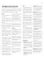
INFORMATION DE SÉCURITÉ
Ce document contient des instructions importantes de sécurité qui
doivent être suivies durant l’installation, la maintenance et l’utilisation
du DCC - Contrôleur de charge pour véhicules électriques.

15
SPÉCIFICATIONS
Le DCC - Contrôleur de charge pour véhicules électriques est un disposi-
tif de sécurité avec un ajustement programmable qui permet de protéger
une distribution électrique en fonction de son disjoncteur principale. Il
permet de prévenir la surcharge d’une distribution électrique en cou-
pant momentanément l’alimentation de la borne de recharge lorsque la
demande excède 80% de la capacité du disjoncteur principale.
Disjoncteur Alimentation principale
Borne de recharge 60A 70A 80A 90A 100A 125A 150A 200A
30A
40A
50A
60A
Tension et câblage 240/208V CA monophasé :
L1, L2, Neutre, Mise à la terre.
Fréquence 50 à 60 Hz
Température d’opération -22°F à 113°F (-30°C à 45°C)
Boitier NEMA 3R
Calibre de câble jusqu’à 250 kcmil (MCM)
Dimensions* (H" x W" x D") 11" x 8" x 5"
Poids total*8 lb (3,63 kg)
*Approximatif, peut changer sans préavis. V2
CARACTÉRISTIQUES
CONDITIONS D’APPLICATIONS
Le DCC - Contrôleur de charge pour véhicules électriques est spécia-
lement conçu pour permettre de connecter une borne de recharge à un
panneau électrique qui autrement n’aurait pas la capacité suffisante
pour permettre le raccordement.
INSTALLATION EXTÉRIEURE
Le DCC-12 a un boîtier NEMA 3R pour les installations intérieures et
extérieures.
ALIMENTATION PRINCIPALE (CB)
Le DCC - Contrôleur de charge pour véhicules électriques peut-être
alimenté par une distribution électrique monophasée de 240/208V CA.
Voici les possibilités en fonction du disjoncteur de la borne de recharge:
Disjoncteur Alimentation principale
Borne de recharge 60A 70A 80A 90A 100A 125A 150A 200A
30A
40A
50A
60A
Tension et câblage 240/208V CA monophasé :
L1, L2, Neutre, Mise à la terre.
Fréquence 50 à 60 Hz
Température d’opération -22°F à 113°F (-30°C à 45°C)
Boitier NEMA 3R
Calibre de câble jusqu’à 250 kcmil (MCM)
Dimensions* (H" x W" x D") 11" x 8" x 5"
Poids total*8 lb (3,63 kg)
*Approximatif, peut changer sans préavis. V2
ALIMENTATION SECONDAIRE (EVC)
Le DCC - Contrôleur de charge pour véhicules électriques peut per-
mettre l’alimentation d’une borne de recharge avec un disjoncteur de
30A, 40A, 50A ou 60A à 240/208V CA, L1, L2 et avec mise à la terre. Le
DCC-12 n’est PAS fourni avec un disjoncteur interne. Le disjoncteur doit
être fourni par l’installateur pour protéger le circuit.
POURCENTAGE DE DÉBARQUEMENT (TP)
Le DCC - Contrôleur de charge pour véhicules électriques est pro-
grammé d’usine pour un débarquement de la borne de recharge si la
consommation totale d’un panneau atteint 80%. Pour une configuration
différente, voir les détails de la configuration "TP" à la page 20.
PANNE DE COURANT
Si une panne de courant se produit, le DCC - Contrôleur de charge pour
véhicules électriques réalimente automatiquement la charge du véhicule
électrique lorsque le courant est rétabli.
TEMPS DE REPRISE (RT)
À la suite d’une coupure d’alimentation de la borne de recharge, un délai
de 15 minutes est enclenché afin de mesurer la consommation totale
de la distribution électrique. Le véhicule électrique sera réalimenté uni-
quement si la puissance requise par le total des charges est inférieure
à 80% du disjoncteur principal durant une période qui excède le temps
de reprise de 15 minutes.

16
CONTRÔLE PAR UN SYSTÈME TIERS (EMS)
La carte de contrôle du DCC dispose d’une entrée de type
contact sec (terminal noir) afin d'être reliée à un système
de gestion d'énergie du bâtiment.
Lorsque le contact est :
- Ouvert, le DCC coupe l’alimentation de la borne de recharge.
- Fermé, le DCC alimente la borne, à la condition que le courant de
l'alimentation principale du DCC soit sous le seuil configuré (80% de
la capacité de l’artère du logement).
La sortie de type contact sec qui reproduit l’état de l’entrée contact
sec permet de mettre en cascade plusieurs DCC sur un seul signal de
contrôle.
EXEMPLES D’INSTALLATION
DCC-12 avec
PANNEAU
PRINCIPAL
POUR MAISONS
DCC-12 avec
PANNEAU
ET COMPTEUR
ÉLECTRIQUE
DCC-12
Lecteurs
de courant
Compteur
électrique
Panneau
principal
Borne de recharge
compatible avec
tous les modèles
DCC-12
Borne de recharge
compatible avec
tous les modèles
Compteur
électrique
Panneau
principal
Lecteurs
de courant
DCC-12
Borne de recharge
compatible avec
tous les modèles
Lecteurs
de courant
Sous panneauCompteur
électrique
Panneau
principal
DCC-12 avec
SOUS PANNEAU

17
INSTALLATION DU DCC
ÉTAPE 1 : VÉRIFIER LE CONTENU DE LA BOÎTE
1 x DCC-12 2 x Transformateurs
de courant (CT)
(6 mètres de fil inclus)
1 x Tournevis
VIDÉO D’INSTALLATION
Pour visionner notre vidéo d’installation,
visitez le www.dccelectrique.com
ÉTAPE 2 : PRÉPARATION À L’INSTALLATION
1. Couper l’alimentation principale
2. Choisir l’emplacement du DCC
Choisir un emplacement qui est préférablement à moins de 5mètres
du panneau électrique (source d’alimentation). Les transformateurs
de courants (CT) qui sont fournis ont un câblage de 5 mètres, mais
peuvent être rallongés (voir la section Étape 4 : Branchement des
conducteurs pour les détails concernant le rallongement).
Le DCC peut s’installer:
- sur un plafond
- sur un mur
NOTE: Le contrôleur DCC doit être installé de sorte que la plaque
signalétique soit visible en tout temps.
Ne pas installer le DCC:
- Dans un endroit où il serait à risque d’être endommagé
- À proximité de matériaux inflammables, explosifs ou combustibles,
produits chimiques, et des vapeurs.
3. Vérifier l’orientation du DCC pour l’installation
Référez-vous aux indications sur le boitier afin d’assurer que
l’orientation de l’installation soit conforme.
ATTENTION
Garantie automatiquement annulée si
l’installation du DCC est non conforme.
ÉTAPE 3 : INSTALLATION
Installation au mur
1. Enlever les 4 vis du couvercle.
2. Positionner le DCC à l’endroit désiré.
3. S’assurer que l’orientation soit conforme aux indications sur le boitier.
4. Fixer le DCC avec des ancrages prévus pour le type de revêtement.
5. Vérifier que le DCC est fixé adéquatement au mur ou au plafond.
ÉTAPE 4 : BRANCHEMENT DES CONDUCTEURS
Consulter le diagramme à la page 20 pour obtenir tous
les détails sur la configuration du branchement des
câbles. Ces diagrammes se trouvent également sous
le couvercle du DCC.
Installation et branchement des transformateurs de courant (CT)
pour le DCC-12
1. Ouvrir les CT.
2. Installer les CT autour du câble d’alimentation principale de l’entrée
électrique.

18
3. Vérifier la polarité des CT.
4. Raccorder les câbles des CT aux borniers (terminal vert) sur la carte
de contrôle du DCC-12 prévus à cet effet.
EXTENSION DES FILS DES TRANSFORMATEURS DE COURANT
Les transformateurs de courant qui sont fournis ont
un câblage de 6mètres. Il est possible de rallonger les câbles.
Le câblage additionnel doit être 300V, minimum 18 AWG (1mm),
4conducteurs avec shielded (ex: FT4 SHIELD. 4C FAS #18
ou équivalent).
ÉTAPE 5A : PROGRAMMATION DE L’ENTRÉE ÉLECTRIQUE
1. Identifier la section à configurer sur le DCC.
2. Configurer la section selon le schéma qui correspond à la puissance
de l’entrée électrique :
Entrée électrique (Ampérage)
Alimentation principale
60A 70A 80A 90A 100A 125A 150A 200A
Borne de
recharge
(disjoncteur)
30A
40A
50A
60A
ÉTAPE 5B : PROGRAMMATION DE LA BORNE DE RECHARGE
Borne de recharge (disjoncteur)
30A 50A
40A 60A
ÉTAPE 6 (OPTIONNELLE) : RACCORDEMENT À UN SYSTÈME
DE GESTION D’ÉNERGIE TIERS
Si un système tiers doit contrôler le DCC, voir l’étape 6 à la fin du
présent manuel.
ÉTAPE 7 : MISE EN MARCHE
Alimentation du DCC
1. Alimenter le DCC en électricité.
2. Attendre dix secondes.
3. Vérifier si le relais est enclenché.
4. Vérifier le témoin lumineux :
VERT en permanence: l’installation est conforme,
passer à la prochaine étape.
ROUGE: se référer à la section Code de lumière.
Alimentation de la borne de recharge
1. Mettre le disjoncteur en position ON.
Si aucun système tiers n’est utilisé avec le DCC, ne
pas enlever le cavalier reliant les deux borniers de
l’entrée EMS IN afin de créer un contact fermé.

19
2. Vérifier si la borne de recharge du véhicule électrique est alimentée:
Borne alimentée: passer à la prochaine étape.
Borne de recharge pas alimentée: vérifier les branchements de la
borne de recharge.
ÉTAPE 8 : SÉCURISER ET RÉALIMENTER
Sécuriser
1. Couper l’alimentation électrique du DCC.
2. Remettre le couvercle.
Réalimenter
1. Alimenter le DCC en électricité.
ÉTAPE 9: IDENTIFICATION
1. Identifier le disjoncteur du DCC dans le panneau électrique.
2. Inscrire les paramètres de configuration de la borne de recharge sur
le couvercle à l’endroit prévu à cet effet.

20
TO INSTALL AROUND THE POWER SUPPLY CABLE
A INSTALLER AUTOUR DES CABLES D’ALIMENTATION DE PANNEAU
LEGEND
R POWER RELAY
DCC ELECTRONIC CONTROLLER
T TRANSFORMER
CT CURRENT TRANSFORMER
IMPORTANT
Wire in accordance with local
and National Electrical codes.
Read instructions carefully before
wiring and operating.
LÉGENDE
R RELAIS DE PUISSANCE
DCC CONTROLEUR ELECTRONIQUE
T TRANSFORMATEUR
CT TRANSFORMATEUR DE COURANT
IMPORTANT
Suivre les codes électriques
nationaux et locaux ainsi que
les instructions contenues
dans l’appareil.
CT
G
R1
R1
R2
R2
CT
DCC ELECTRONIC CONTROLLER
CONTROLEUR ELECTRONIQUE DCC
PB SWITCH
(RESET)
LED
2W 2B 1B1W
Blue / Bleu
White / Blanc
Green / Vert
24V
208 / 240V
TRANSFORMER
TRANSFORMATEUR
POWER RELAY
RELAIS DE PUISSANCE
POWER RELAY
RELAIS DE PUISSANCE
12VA
Yellow / Jaune
Orange / Orange
R1
L1 T1 L2 T2
G
Red / Rouge
Black / Noir
Black / Noir
White / Blanc
Black / Noir
White / Blanc
G
R2
ELECTRIC VEHICLE
CHARGER
BORNE DE RECHARGE
208V / 240V 1PH
ALIMENTATION
DU PANNEAU
208V / 240V 1PH
CURRENT TRANFORMERS
TRANSFORMATEUR
DE COURANT
T
POWER SUPPLY
DRAWING NO. DCC-12 CONTROLLER
DATE
01-28-2020
PER
TITLE
DCC-12 CONTROLLER GEN 3 (G3)
BOITIER DE CONTROLE DCC-12 GEN 3 (G3)
CONFIGURATION DIAGRAMS / DIAGRAMMES DE CONFIGURATION
Trip Percentage (%)
Pourcentage de débarquement (%)
Reintegration Time (Minutes)
Temps de reprise (Minutes)
Trip Delay: 15 seconds (Default)
Temps de débarquement: 15 secondes (Défaut)
EV Charger (Breaker)
Borne de recharge (Disjoncteur)
80% (Default / Défaut)
15 Min (Default / Défaut)
OFFON
Main Circuit Breaker (Amps)
Entrée électrique (Ampérage)
Main power supply / Alimentation principale
60A 70A 80A 90A 100A
125A 150A 200A
30A ✓ ✓ ✓ ✓ ✓ ✓ ✓ ✓
40A ✗ ✗ ✓ ✓ ✓ ✓ ✓ ✓
50A ✗ ✗ ✗ ✗ ✓ ✓ ✓ ✓
60A ✗ ✗ ✗ ✗ ✗ ✓ ✓ ✓
EV Charger
(Breaker) /
Borne de recharge
(Disjoncteur)
Red / Rouge
Black / Noir
THERMOLEC V.7
DCC V.3
IN IL ILOUT
TO NEXT DCC
AU SUIVANT DCC
ENERGY MANAGEMENT SYSTEM
SYSTÈME DE GESTION D’ÉNERGIE
TERMINAL
Black / Noir
TERMINAL
Green / Vert
30A DCC-12-30A 40A DCC-12-40A 50A DCC-12-50A 60A DCC-12-60A
60% 70% 80%
La page est en cours de chargement...
La page est en cours de chargement...
-
 1
1
-
 2
2
-
 3
3
-
 4
4
-
 5
5
-
 6
6
-
 7
7
-
 8
8
-
 9
9
-
 10
10
-
 11
11
-
 12
12
-
 13
13
-
 14
14
-
 15
15
-
 16
16
-
 17
17
-
 18
18
-
 19
19
-
 20
20
-
 21
21
-
 22
22


dans d''autres langues
- English: Thermolec DCC-12 User manual
Documents connexes
Autres documents
-
THERMOLEC LTEE DCC-9-PCB Manuel utilisateur
-
THERMOLEC LTEE DCC 10 Electric Vehicle Energy Manuel utilisateur
-
THERMOLEC LTEE DCC-11-BOX Manuel utilisateur
-
DCC Electric DCC-11 Gen 2 Manuel utilisateur
-
THERMOLEC LTEE DCC-9-BOX Manuel utilisateur
-
Legrand 057012 Mode d'emploi
-
 Topdon PulseQ AC Home Manuel utilisateur
-
Hornby R8239 Booster Le manuel du propriétaire
-
Sony AC-VQ1050D Manuel utilisateur
-
Märklin 36632 Manuel utilisateur
