Flotec Simer Self-Priming Centrifugal Pumps Le manuel du propriétaire
- Catégorie
- Pompes à eau
- Taper
- Le manuel du propriétaire
Ce manuel convient également à

PENTAIR.COM
OWNER'S MANUAL
SELF-PRIMING CENTRIFUGAL PUMPS
P15006 (02-01-2023)
©2023 Pentair. All Rights Reserved.
®
FLOTEC SIMER
ENGLISH: 1-16 FRENCH: 17-32 SPANISH: 33-48

2 P15006 (02-01-2023)
TABLE OF CONTENTS
SAFETY INSTRUCTIONS ..................................................................................................3
INSTALLATION & OPERATION .............................................................................................4
ELECTRICAL ............................................................................................................6
OPERATIONS ............................................................................................................7
MAINTENANCE ..........................................................................................................8
REPAIR PARTS .........................................................................................................10
TROUBLESHOOTING ..................................................................................................... 14
WARRANTY ............................................................................................................15
THIS MANUAL COVERS THE FOLLOWING MODEL SERIES:
FLOTEC: FP5242, FP5252, FP5512, FP5522, FP5532, FP5542, FP5552, FP5162, FP5172, FP5182
SIMER: 3410P, 3415P, 3420P.

3
P15006 (02-01-2023)
SAFETY INSTRUCTIONS
SAFETY SYMBOLS
This is the safety alert symbol. When you see this symbol on
your pump or in this manual, look for one of the following signal
words and be alert to the potential for personal injury:
warns about hazards that will cause serious
personal injury, death or major property damage if ignored.
warns about hazards that can cause serious
personal injury, death or major property damage if ignored.
warns about hazards that will or can cause minor
personal injury or property damage if ignored.
The word NOTE indicates special instructions that are important
but not related to hazards.
CALIFORNIA PROPOSITION 65 WARNING
This product and related accessories contain
chemicals known to the State of California to cause cancer,
birth defects or other reproductive harm.
GENERAL SAFETY
DO NOT TOUCH AN OPERATING MOTOR. Modern
motors can operate at high temperatures. To avoid burns when
servicing pump, allow it to cool for 20 minutes after shut-down
before handling.
Pump is designed as a lawn sprinkler only. To avoid heat
buildup, over-pressure hazard, and possible injury, do not
use in a pressure tank (domestic water) system. Do not use
as a booster pump; pressurized suction may cause pump
body to explode.
Do not allow pump or piping system to freeze. Freezing can
damage pump and pipe, may lead to injury from equipment
failure, and will void warranty.
Pump only water with this unit.
Periodically inspect pump and system components.
Wear safety glasses at all times when working on pumps.
Keep work area clean, uncluttered and properly lighted;
properly store all unused tools and equipment.
Keep visitors at a safe distance from the work areas.
Make workshops childproof; use padlocks and master
switches; remove starter keys.
ELECTRICAL SAFETY
Wire motor for correct voltage. See “Electri cal” section of
this manual and motor nameplate.
Ground motor before connecting to power supply.
Meet National Electri cal Code, Canadian Elec tri cal Code,
and local codes for all wiring.
Follow wiring instructions in this manual when connecting
motor to power lines.
Hazardous voltage. Can shock, burn, or
cause death.
Ground pump before connecting to power
supply.

4 P15006 (02-01-2023)
PRIOR TO PUMP INSTALLATION
Ensure the well is not more than 20 foot depth to water.
Locate pump as close to the well as possible, using use as
few elbows and fittings as possible. Long runs and many
fittings increase friction and reduce flow.
Ensure the well is clear of sand. Sand will clog the pump and
void the warranty.
Protect pump and all piping from freezing. Freezing will split
pipe, damage pump and void the warranty. Check local frost
protection requirement. Usually piping must be 12" below
frost line and the pump must be insulated.
Be sure all pipes and the foot valve are clean and in good
shape.
Ensure there are no air pockets or leaks in suction pipe. Use
PTEE pipe thread sealant tape to seal pipe joints.
Unions installed near the well and pump aid in servicing.
Make sure to leave room for use of wrenches.
PUMP BODY MAY EXPLODE if used as a booster
pump. DO NOT use in a booster appli cation.
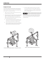
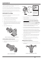
WELL PIPE INSTALLATION
Use the installation method below that matches your well type.
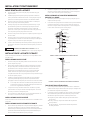
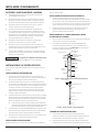
CASED WELL INSTALLATION
1. Inspect foot valve to be sure it works freely. Inspect strainer
to be sure it is clean.
2. Connect foot valve and strainer to the first length of
suction pipe and lower pipe into well. Add sections of pipe
as needed, using PTFE pipe thread sealant tape on male
threads. Be sure that all suction pipe is leak proof or pump
will lose prime and fail to pump.
3. Install foot valve 10 to 20 feet below the lowest level to
which water will drop while pump is operating (pumping
water level). Your well driller can furnish this in formation.
To prevent sand and sediment from entering the
pumping system, the foot valve/strainer should be at
least 5 feet above the bottom of the well.
4. When the proper depth is reached, install a sanitary well
seal over the pipe and in the well casing. Tighten the bolts to
seal the casing.
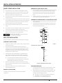
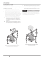
5. When using a foot valve, a priming tee and plug are
recommended (Figure 1).
DUG WELL INSTALLATION
Follow the same instructions as outlined in Cased Well
Installation.
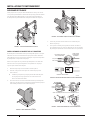
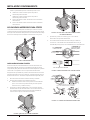
DRIVEN WELL POINT INSTALLATION
1. Connect the suction pipe to the drive point (Figure 2). Keep
horizontal pipe run as short as possible. Use PTFE pipe
thread sealant tape on male pipe threads. Multiple well
points may be necessary to provide sufficient water to
pump.
2. Install a check valve in horizontal pipe. Ensure the check
valve's flow arrow point toward the pump.
HORIZONTAL PIPING FROM WELL TO PUMP INSTALLATION
1. Never install a suction pipe that is smaller than the suction
port of the pump.
2. To aid priming with well point installations, install a check
valve as shown in Figure 2. Ensure the check valve's flow
arrow point toward the pump.
Suction
pipe
Foot
Valve
Priming plug
Priming tee
Drawdown water
level (pump on)
10-20' (3-6 m)
20' (6 m)
max.
At least 5 feet
(1.5 m)
828 1011
Standing water
level (pump off)
FIGURE 1 –
CASED/DUG WELL INSTALLATION
Check valve
Steel drive pipe
Drive coupling
Driven point
745 0993
FIGURE 2 – DRIVEN POINT INSTALLATION
DISCHARGE PIPE SIZES
1. If increasing discharge pipe size, install reducer in pump
discharge port. Do not increase pipe size by stages.
2. When the pump is set away from the points of water use,
the discharge pipe size should be increased to reduce
pressure losses caused by friction.
Up to 100’ run: Same size as pump discharge port.
100’ to 300’ run: Increase one pipe size.
300’ to 600’ run: Increase two pipe sizes.
INSTALLATION & OPERATION

5
P15006 (02-01-2023)
INSTALLATION & OPERATION
20 100
80
60
40
3024 0997
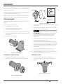
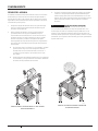
FIGURE 5 – INDEPENDENTLY SUPPORT PIPING ATTACHED TO PUMP
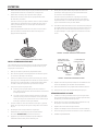
4. Tighten joints hand tight plus 1-1/2 turns. Do not over
tighten.
5. If long, horizontal pipe runs have to be used, install a
priming tee between the check valve and the well head
(Figure 1). Use schedule 80 or iron pipe.
1102 0697
No Air Leaks
in Suction Pipe.
Pipe Joint
Compound Will
Damage Plastic.
If Air Flows
Water Won’t
Use PTFE Tape
FIGURE 6 – NO AIR POCKETS IN SUCTION PIPE
FIGURE 7 – SUCTION PIPE MUST NOT LEAK
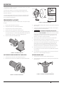
LAWN SPRINKLING APPLICATION
This pump is designed for a pond, cistern or well points. Pump
discharge can be divided to supply two (2) or more sprinkler
systems. A suggested multiple dis charge to service is shown in
Figure 3.
20 100
80
60
40
1909 0997
FIGURE 3 – MULTIPLE DISCHARGE
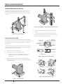
PUMP/PIPING INSTALLATION
Use only pipe thread sealant tape for making all threaded
connections to the pump itself. Do not use pipe joint compounds
on plastic pumps: they can react with the plastic in the pump
components.
Make sure that all pipe joints in the suction pipe are air tight as
well as water tight. If the suction pipe can suck air, the pump will
not be able to pull water from the well.
1. Bolt pump to solid, level foundation.
2. Support all piping connected to the pump.
Install pump as close to well head as poss ible. Long
piping runs and many fittings create friction and
reduce flow.
3. Wrap 1-1/2 to 2 layers of PTFE pipe thread sealant tape
clockwise (as you face end of pipe) on all male threads being
attached to pump.
3023 0997
FIGURE 4 – BOLT PUMP DOWN
748 0993
Don’t Hit
Thread Stops
Don’t
Overtighten
From
Well
Pump
Body
Hand Tight Plus 1-1/2 Tu rns With Wrench.

6 P15006 (02-01-2023)
ELECTRICAL
WIRING
Install, ground, wire and maintain this pump in accordance
with electrical code requirements. Consult your local building
inspector for information about codes. Read and follow all
warnings below.
HAZARDOUS VOLTAGE. Can shock, burn or kill.
Disconnect power to motor before working on pump or motor.
Ground motor before connecting to power supply.
To avoid dangerous or fatal electrical shock, turn OFF power
to motor before working on electrical connections.
Supply voltage must be within ±10% of nameplate voltage.
Incorrect voltage can cause fire or damage motor and voids
warranty. If in doubt consult a licensed electrician.
Use wire size specified in this manual's Wiring Chart.
Wire motor according to diagram on motor nameplate. If
nameplate diagram differs from this manual's diagrams, follow
nameplate diagram.
1. Provide a correctly fused disconnect switch for protection
while working on motor. Consult local or national electrical
codes for switch requirements*.
2. Disconnect power before servicing motor or pump. If the
disconnect switch is out of sight of pump, lock it open and
tag it to prevent unexpected power application.
3. Ground the pump permanently using a wire of the same size
as specified in this manual's Wiring Chart. Make ground
connection to green grounding terminal under motor
canopy marked GRD. or .
4. Connect ground wire to a grounded lead in the service
panel or to a metal underground water pipe or well casing
at least 10 feet long. Do not connect to plastic pipe or
insulated fittings.
Do not ground to a gas supply line.
5. Protect current carrying and grounding conductors from
cuts, grease, heat, oil, and chemicals.
6. Motor has automatic internal thermal overload protection.
If motor has stopped for unknown reasons, thermal
overload may restart it unexpectedly, which could cause
injury or property damage. Disconnect power before
servicing motor.
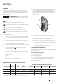
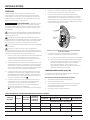
Voltage
Change Dial
Ground
Screw
Power Lead
Te rminals
4695
FIGURE 8 - VOLTAGE SET TO 230 VOLT CURRENT. ROTARY SELECTOR
7. If this procedure or the wiring diagram are confusing,
consult a licensed electrician
Refer to Figure 8 for wiring configuration.
Connect current-carrying conductors to terminals
L1 and L2. When replacing the motor, check wiring
diagram on the motor nameplate. For 3-phase motors
or motor's whose wiring diagram does not match
Figure 8, follow the diagram on the motor.
115 VOLT USAGE CONFIGURATION
115/230 volt, single phase models are configured at the factory
for 230 volt usage.
If power supply will be 115 volts:
1. Ensure power is off.
2. Remove motor cover.
3. Using a screwdriver or 1/2" wrench, turn the voltage
selector dial counter-clockwise to the 115 volt setting.
4. Replace motor cover.
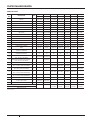
HORSEPOWER VOLTAGE MAX. LOAD
AMPS
BRANCH FUSE
RATING AMP
DISTANCE IN FEET (METERS) FROM MOTOR TO SUPPLY
0-100 (0-30) 101-200 (31-61) 201-300 (62-91) 301-400 (92-122)
AWG WIRE SIZE - 115V/230V (MM
2
)
1115/230 12.2/6.1 25/15 12/14 (3/2) 8/14 (8.4/2) 8/14 (8.4/2) 6/12 (14/3)
1-1/2 115/230 18.4/9.2 30/20 10/14 (5.5/2) 8/14 (8.4/2) 6/12 (14/3) 4/10 (21/5.5)
2115/230 22.8/11.4 45/25 10/14 (5.5/2) 6/12 (14/3) 6/12 (14/3) 4/10 (21/5.5)
(*) Dual element or Fusetron time delay fuses recommended for all motor circuits.
WIRING CHART RECOMMENDED WIRE AND FUSE SIZES

7
P15006 (02-01-2023)
OPERATIONS
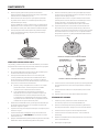
PRIMING THE PUMP
Priming refers to the pump expelling all air in the system and
beginning to move water from its source out into the system.
It does not refer only to pouring water into the pump (although
pouring water in is usually the first step).
1. Make sure suction and discharge valves and any hoses on
discharge side of pump are open.
2. Remove priming plug. Fill pump and suction pipe with water
(Figure 9). NEVER run pump dry. Running pump without
water in it will damage seals and can melt impeller and
diffuser. Be sure discharge (valve, pistol grip hose nozzle,
etc.) is open whenever pump is running.
If a priming tee and plug have been provided for a long
horizontal run, be sure to fill suction pipe through this
tee and replace plug. Remember to tape the plug.
Replacing the existing priming plug with one that has a
pressure gauge and reducer bushing mounted in it will
make troubleshooting pump performance easier.
3. Start pump. Water should be produced in 10 minutes or
less. The time depends on the well's depth to water and
the length of horizontal run. If no water is produced within
10 mins., stop pump, release all pressure, remove priming
plug, refill, and try again.
HAZARDOUS PRESSURE AND RISK OF EX PLO SION
AND SCALDING. If pump is run con ti nu ously at no flow (that is,
with discharge shut off or without priming), water may boil in
pump and piping system. Under steam pressure, pipes may
rupture, blow off of fittings or blow out of pump ports and
scald anyone near.
20 100
80
60
40
3025 0997
FIGURE 9 – REMOVE PRIMING PLUG AND FILL PUMP BEFORE STARTING
20 100
80
60
40
3026 0997
FIGURE 10 – DO NOT RUN PUMP WITH DISCHARGE SHUT-OFF

8 P15006 (02-01-2023)
MAINTENANCE
The pump and piping do not need to be disconnected to repair or
replace the motor or seal.
If motor is replaced, a new shaft seal must be installed. Keep an
extra shaft seal on hand for future needs.
Check motor label for lubrication instructions. The mechanical
shaft seal in the pump is water lubricated and self-adjusting.
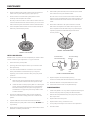
PUMP DISASSEMBLY
Drain pump when disconnecting from service or when it might
freeze.
1. Disconnect power to motor.
2. Mark wires for correct assembly.
3. Release all water pressure from system.
4. Remove drain plug and drain pump.
5. Remove cap screws holding seal plate to pump body. Motor
assembly and seal plate can now be pulled away from pump
body (Figure 11).
6. CARE FULLY remove gasket.
3027 0997
FIGURE 11 – SLIDE MOTOR BACK
CLEANING/REPLACING IMPELLER
1. Follow instructions under “Pump Dis assembly”.
2. Remove screws fastening the diffuser to the seal plate.
3028 0997
FIGURE 12 – REMOVE DIFFUSER
FIGURE 13 – HOLD SHAFT
To avoid electrical
shock hazard, use
insulated-handle
screwdriver to short
capacitor terminals
as shown.
3. Remove diffuser (Figure 12). The exposed impeller can now
be cleaned.
4. If impeller must be replaced, loosen two machine screws
and remove motor canopy (Figure 13).
5. CAPACITOR VOLTAGE MAY BE HAZARDOUS.
To discharge capacitor, hold insulated handle screwdriver
BY THE HANDLE and short capacitor terminals together
(Figure 13). Do not touch metal screwdriver blade or
capacitor terminals. If in doubt, consult a qualified
electrician.
6. Unscrew capacitor clamp and remove capacitor. Do not
disconnect capacitor wires to motor.
7. Slide a 7/16" open-end wrench behind the spring-loaded
switch on the motor end of the shaft. Hold motor shaft with
wrench on shaft flats and unscrew impeller screw (if used)
by turning clockwise (left hand thread) when looking into
eye of impeller.
8. Unscrew impeller while holding shaft by turning
counterclockwise while looking into eye of impeller.
9. To reinstall, reverse steps 1 through 6 and follow directions
in the "Pump Reassembly" section below.
REMOVING OLD SEAL
1. Follow instructions under “Pump Disassembly”.
2. Follow steps 2 through 5 under “Cleaning/Replacing
Impeller”.
3029 0997
FIGURE 14 – REMOVE SEAL PLATE

9
P15006 (02-01-2023)
MAINTENANCE
3. Remove rotating half of seal by placing two screw drivers
under seal ring and carefully prying up (Figure 14).
4. Remove nuts from studs holding seal plate to motor.
Carefully slide seal plate off of shaft.
Be sure you do not scratch or mar shaft. If shaft is marred,
it must be dressed smooth with fine emery or crocus cloth
before installing new seal. DO NOT reduce shaft diameter!
5. Place seal plate half face down on flat surface and tap out
stationary half of seal (Figure 15).
3030 0997
FIGURE 15 – TAP OUT SEAL
INSTALLING NEW SEAL
Gaskets and o-rings are not interchangeable per models. Make
sure to install the type of gasket or o-ring you removed.
1. Clean seal cavity in seal plate.
2. Sparingly wet outer edge of rubber cup on ceramic seat
with liquid soap.
3. Put clean cardboard washer on seal face. The ceramic
seal's polished face should be facing up. Firmly and
squarely, press ceramic seal into cavity using only hand
pressure.
4. If seal will not seat correctly:
Remove seal, placing polished side up on bench. Re-
clean cavity and install as outlined in previous step.
If seal still does not seat properly after re-cleaning the
cavity, place a cardboard washer over polished seal
face and carefully press into place using a piece of
standard 3/4 inch pipe as a press being careful not to
scratch seal face."
5. Dispose of cardboard washer and recheck seal face to
be sure it is free of dirt, foreign particles, scratches and
grease.
6. Inspect shaft to be sure it is free of nicks and scratches.
7. Reassemble pump body half to motor flange. BE SURE it is
right side up.
8. Apply liquid soap sparingly (one drop is sufficient) to inside
diameter of rotating seal member.
9. Slide rotating seal member (carbon face first) onto shaft
until rubber drive ring hits shaft shoulder.
Be sure not to nick or scratch carbon face of seal when
passing it over threaded shaft end or shaft shoulder. The
carbon surface must remain clean or short seal life will
result.
10. Hold motor shaft with 7/16” open end wrench on shaft
flats and screw impeller onto shaft. Be sure you do not
touch capacitor terminals with body or any metal object.
Tightening impeller will automatically locate seal in
correct position.
3031 0997
FIGURE 16 – PRESS IN NEW SEAL
1072 0697
Ceramic
Face Carbon
Face
Be Careful That
Motor Shaft Shoulder...
...Does Not Damage
Seal Face
FIGURE 17 – PROTECT SEAL FACES
11. Replace impeller screw (if used) by turning
counterclockwise (left-hand thread) into end of shaft.
12. Remount diffuser on seal plate with two screws.
13. Follow instructions under “Pump Reassembly”.
PUMP REASSEMBLY
1. Install new gasket or O-ring. Note to replace with using the
same as the pump was originally manufactured with.
2. Slide motor/seal plate assembly into pump body. Secure
with cap screws.
3. Replace base mounting bolts.
4. Replace motor wiring; close drain cock.
5. Prime pump according to instructions. See “Opera tion.”
6. Check for leaks.

10 P15006 (02-01-2023)
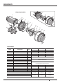
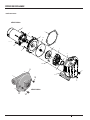
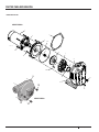
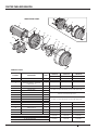
REPAIR PARTS
9
12
12
12
2419A 0605
1
2
3
14
13
6
7B
10
12
11
5
6
7
8
6A
4a
9
4
7A
FP5200 SERIES
FP5500 SERIES
FLOTEC MODELS

11
P15006 (02-01-2023)
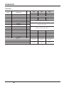
KEY
NO. DESCRIPTION QTY FP5242-00 FP5252-00 FP5512-00 FP5522-00 FP5532-00 FP5542-00 FP5552-00
1-1/2 HP 2 HP 1/2 HP 3/4 HP 1 HP 1-1/2 HP 2 HP
1MOTOR 1J218-1655 J218-1656 J218-1651 J218-1652 J218-1653 J218-1655 J218-1656
2WATER SLINGER 117351-0009 17351-0009 17351-0009 17351-0009 17351-0009 17351-0009 17351-0009
3SEAL PLATE 1C3-155-SR C3-117 C3-178 C3-178 C3-178 C3-178 C3-181
4 SEAL PLATE GASKET 1 C20-86 C20-87 C20-121N C20-121N C20-121N C20-121N C20-122N
4A O-RING 125276 34516 - - - - -
5SHAFT SEAL 1U109-6B U109-6B U109-6B U109-6B U109-6B U109-6B U109-6B
6IMPELLER 1C105-92PCB C105-214PDA C105-92PN C105-92PM C105-92PL C105-92PB C105-
214PCA
6A IMPELLER SCREW 1 - C30-14SS - - - - -
7DIFFUSER 1C101-276P C101-182 - - - - -
7A SCREW - 1/4" - 20 X 1" LG. 2 U30-696SS - - - - - -
7A SCREW - 8 - 32 X 7/8" LG. 2 - U30-53SS - - - - -
8DIFFUSER RING 1C21-10 C21-2 C23-27 C23-27 C23-27 C23-27 C23-19
9PUMP BODY 1C76-49B C76-50 C101-284E C101-284E C101-284E C101-284E C101-264E
10 BASE 1U4-5 U4-5 J204-9 J204-9 J204-9 J204-9 J104-9
11 PIPE PLUG - 3/4" NPT SQ. HD. 1 U78-60ZPS U78-60ZPS - - - - -
12 PIPE PLUG - 1/4" NPT HEX HD. ( ) U78-941ZPV
(1)
U78-941ZPV
(1)
U78-941ZPV
(3)
U78-941ZPV
(3)
U78-941ZPV
(3)
U78-941ZPV
(3)
U78-941ZPV
(3)
13 HEX CAP SCREW - 3/8" - 16 X 3/4" LG. ( ) U30-72ZP (8) U30-72ZP (2) - - - - -
13 HEX CAP SCREW - 5/16" - 18 X 3/4" LG. 8 - U30-60ZP - - - - -
14 CAP SCREW - 3/8" - 16 X 1" 4 U30-74ZP U30-74ZP - - - - -
14 CAP SCREW - 3/8" - 16 X 1-1/4" LG. (TOP) 2 - - U30-75ZP U30-75ZP U30-75ZP U30-75ZP -
14 CAP SCREW - 3/8" - 16 X 1" LG. (TOP) 2 - - - - - - U30-74ZP
14 CAP SCREW - 3/8" - 16 X 1-1/2" LG.
(BOTTOM) 2 - - U30-76ZP U30-76ZP U30-76ZP U30-76ZP -
14 CAP SCREW - 3/8" - 16 X 1-1/4" LG.
(BOTTOM) 2 - - - - - - U30-75ZP
* LOCK WASHER - 3/8" 8 U43-12ZP U43-12ZP - - - - -
* CAP SCREW - 3/8" - 16 X 5/8" LG 2 U30-71ZP U30-71ZP - - - - -
*MOTOR PAD 1 - - C35-5 C35-5 C35-5 C35-5 C35-5
SEAL KIT - - PP1700 PP1700 PP1700 PP1700 PP1700
(INCLUDES 3, 5, AND 8)
REPAIR PARTS
* Not pictured
FLOTEC MODELS

12 P15006 (02-01-2023)
4
3
13
12
L
1
7
6
-
3
5
P
1
2
4
3
5
6
7
8
9
10
13
12
11
14
15
8
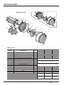
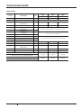
REPAIR PARTS
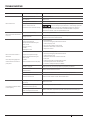
KEY NO. DESCRIPTION QTY FP5162-08 FP5172-08 FP5182-08
1 HP 1-1/2 HP 2 HP
1MOTOR 1J218-1653 J218-1655 J218-1656
2WATER SLINGER 1 Included in Seal Kit and Overhaul Kit
3PRIMING PLUG -1/2" PIPE PLUG 1 - - -
4SEAL PLATE 1L176-47P1 L176-47P1 C103-189P
5 SEAL PLATE O-RING 1 Included in Seal Kit and Overhaul Kit
6SHAFT SEAL 1
7IMPELLER 1Included in Overhaul Kit
8DIFFUSER 1
9 SCREW - #8 - 32 X 1" LG. 4
Included in Seal Kit and Overhaul Kit* LOCK WASHER -
10 DIFFUSER O-RING 1
11 CLAMP 1C19-54SS C19-54SS C19-37A
12 PUMP BODY 1C176-53P C176-53P C176-62P
13 DRAIN PLUG - 1/4" PIPE PLUG 1 - - -
14 BASE 1C4-42P C4-42P C4-42P
15 MOTOR PAD 1 - - -
SEAL KIT FPP5000 FPP5000 FPP5000
(Includes 2, 5, 6, 9, 10, and Lock Washer)
OVERHAUL KIT FPP5001 FPP5002 FPP5008
(Includes 2, 5, 6, 7, 8, 9, 10, and Lock Washer)
4
3
13
12
L
1
7
6
-
3
5
P
1
2
4
3
5
6
7
8
9
10
13
12
11
14
15
8
FLOTEC MODELS
FP5100/3400P SERIES

13
P15006 (02-01-2023)
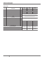
REPAIR PARTS
KEY NO. DESCRIPTION QTY 3410P 3415P 3420P
1 HP 1-1/2 HP 2 HP
1MOTOR 1J218-1653 J218-1655 J218-1656
2WATER SLINGER 1 Included in Seal Kit and Overhaul Kit
3PRIMING PLUG -1/2" PIPE PLUG 1 - - -
4SEAL PLATE 1L176-47P1 L176-47P1 C103-189P
5 SEAL PLATE O-RING 1 Included in Seal Kit and Overhaul Kit
6SHAFT SEAL 1
7IMPELLER 1Included in Overhaul Kit
8DIFFUSER 1
9 SCREW - #8 - 32 X 1" LG. 4
Included in Seal Kit and Overhaul Kit* LOCK WASHER -
10 DIFFUSER O-RING 1
11 CLAMP 1C19-54SS C19-54SS C19-37A
12 PUMP BODY 1C176-53P C176-53P C176-62P
13 DRAIN PLUG - 1/4" PIPE PLUG 1 - - -
14 BASE 1C4-42P C4-42P C4-42P
15 MOTOR PAD 1 - - -
SEAL KIT FPP5000 FPP5000 FPP5000
(Includes 2, 5, 6, 9, 10, and Lock Washer)
OVERHAUL KIT FPP5001 FPP5002 FPP5008
(Includes 2, 5, 6, 7, 8, 9, 10, and Lock Washer)
SIMER MODELS

14 P15006 (02-01-2023)
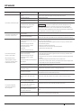
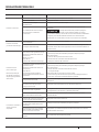
TROUBLESHOOTING
SYMPTOM PROBABLE CAUSE(S) CORRECTIVE ACTION
Motor will not run
Disconnect switch is off Be sure switch is on
Fuse is blown Replace fuse
Starting switch is defective Replace starting switch
Wires at motor are loose,
disconnected, or wired incorrectly
Refer to instructions on wiring. Check and tighten all wiring.
Capacitor voltage may be hazardous. To discharge capacitor,
hold insulated handle screwdriver BY THE HANDLE and short capacitor
terminals together. Do not touch metal screwdriver blade or capacitor
terminals. If in doubt, consult a qualied electrician.
Motor runs hot and overload
kicks off
Motor is wired incorrectly Refer to wiring instructions
Voltage is too low Check with power company. Install heavier wiring if wire size is too small
(See Electrical section of this manual)
Motor runs but no water is
delivered
Unscrew priming plug and
make sure there is water in
pump case.
Pump in new installation did not
pick up prime through:
Check prime before looking for
other causes.
Improper priming
Air leaks
Leaking foot valve
In new installation:
1. Unscrew priming plug and make sure there
is water in pump case
2. Re-prime according to instructions
3. Check all connections on suction line
4. Replace foot valve
Pump has lost prime through:
Check prime before looking for
other causes.
Air leaks
Water level below suction of pump
In installation already in use:
1. Unscrew priming plug and make sure there
is water in pump case
2. Check all connections on suction line and
shaft seal
3. Lower suction line into water and re-prime.
If receding water level in well exceeds
suction lift, a deep well pump is needed
Impeller is plugged Clean impeller as per Cleaning/replacing Impeller procedures.
Check valve or foot valve is stuck in
closed position Replace check valve or foot valve
Pipes are frozen Thaw pipes. Bury pipes below frost line. Heat pit or pump house
Foot valve and/or strainer are
buried in sand or mud Raise foot valve and/or strainer above well bottom
Pump does not deliver water
to full capacity
Leaking foot valve is causing lose
of priming Replace foot valve
Water level in well is greater than 25
feet below suction of pump
A deep well jet pump may be needed
Steel piping (if used) is corroded or
limed, causing excess friction Replace with plastic pipe where possible, otherwise with new steel pipe
Offset piping is too small in size Use larger offset piping

15
P15006 (02-01-2023)
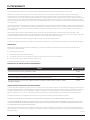
LIMITED WARRANTY
This Limited Warranty is effective July 11, 2019 and replaces all undated warranties and warranties dated before July 11, 2019.
Pentair Flotec* warrants to the original consumer purchaser (“Purchaser” or “You”) that its products are free from defects in material and
workmanship for a period of twelve (12) months from the date of the original consumer purchase. If, within twelve (12) months from the original
consumer purchase, any such product shall prove to be defective, it shall be repaired or replaced at Pentair Flotec’s option, subject to the terms and
conditions set forth herein. Note that this limited warranty applies to manufacturing defects only and not to ordinary wear and tear. All mechanical
devices need periodic parts and service to perform well. This limited warranty does not cover repair when normal use has exhausted the life of a part
or the equipment.
The original purchase receipt and product warranty information label are required to determine warranty eligibility. Eligibility is based on purchase
date of original product – not the date of replacement under warranty. The warranty is limited to repair or replacement of original purchased product
only, not replacement product (i.e. one warranty replacement allowed per purchase). Purchaser pays all removal, installation, labor, shipping, and
incidental charges.
Claims made under this warranty shall be made by returning the product (except sewage pumps, see below) to the retail outlet where it was
purchased immediately after the discovery of any alleged defect. Pentair Flotec will subsequently take corrective action as promptly as reasonably
possible. No requests for service will be accepted if received more than 30 days after the warranty expires.
Warranty is not transferable and does not apply to products used in commercial/rental applications.
For parts or troubleshooting assistance, DO NOT return product to your retail store - contact Pentair Flotec Customer Service at 1-800-365-6832.
SEWAGE PUMPS
DO NOT return a sewage pump (that has been installed) to your retail store. Sewage pumps that have seen service and been removed carry a
contamination hazard with them.
If your sewage pump has failed:
Wear rubber gloves when handling the pump;
For warranty purposes, return the pump’s cord tag and original receipt of purchase to the retail store;
Dispose of the pump according to local disposal ordinances.
Contact Pentair Flotec Customer Service at 1-800-365-6832.
EXCEPTIONS TO THE TWELVE (12) MONTH LIMITED WARRANTY
GENERAL TERMS AND CONDITIONS; LIMITATION OF REMEDIES
You must pay all labor and shipping charges necessary to replace product covered by this warranty. This warranty does not apply to the following: (1)
acts of God; (2) products which, in the sole judgment of Pentair Flotec, have been subject to negligence, abuse, accident, misapplication, tampering,
or alteration; (3) failures due to improper installation, operation, maintenance or storage; (4) atypical or unapproved application, use or service;
(5)failures caused by corrosion, rust or other foreign materials in the system, or operation at pressures in excess of recommended maximums.
This warranty sets forth the sole obligation of Pentair Flotec, and purchaser’s exclusive remedy for defective products.
PENTAIR FLOTEC SHALL NOT BE LIABLE FOR ANY CONSEQUENTIAL, INCIDENTAL, OR CONTINGENT DAMAGES WHATSOEVER.
THE FOREGOING WARRANTIES ARE EXCLUSIVE AND IN LIEU OF ALL OTHER EXPRESS AND IMPLIED WARRANTIES, INCLUDING BUT NOT LIMITED
TO THE IMPLIED WARRANTIES OF MERCHANTABILITY AND FITNESS FOR A PARTICULAR PURPOSE. THE FOREGOING WARRANTIES SHALL NOT
EXTEND BEYOND THE DURATION PROVIDEDHEREIN.
Some states do not allow the exclusion or limitation of incidental or consequential damages or limitations on how long an implied warranty lasts, so
the above limitations or exclusions may not apply to You. This warranty gives You specific legal rights and You may also have other rights which vary
from state to state.
(3/10/2022)
PRODUCT WARRANTY PERIOD
Parts2O* (Parts & Accessories), FP0F360AC, FP0FDC 90 days
FP0S1775A, FP0S4100X, FPPSS3000, FPCC5030, FPCI3350, FPCI5050, FPDC30 2 Years
FPSC1725X, FPSE3601A, FPSC3350A, FPZT7300, FPZT7350, FPZT7450, FPZT7550 2 Years
FP7100/FP7400 Series Pressure Tanks, E3305TLT, E3375TLT, E5005TLTT, E50TLT, E50VLT, E75STVT, E75VLT,
FPSE9000, FPSE9050 5 Years
FLOTEC WARRANTY

All indicated Pentair trademarks and logos are property of Pentair. Third party registered and unregistered trademarks and logos are the property of their respective owners. Because we are
continuously improving our products and services, Pentair reserves the right to change specications without prior notice. Pentair is an equal opportunity employer.
©2023 Pentair. All Rights Reserved. P15006 (02-01-2023)
293 Wright Street
Delavan, WI 53115
Ph: 800.365.6832
Fx: 800.426.9446
490 Pinebush Rd., Unit 4
Cambridge, Ontario
Canada N1T 0A5
Ph: 800.363.7867
Fx: 888.606.5484
PENTAIR.COM
SIMER WARRANTY
Rev. 03-10-2022
RETAIN ORIGINAL RECEIPT FOR WARRANTY ELIGIBILITY
LIMITED WARRANTY
This Limited Warranty is effective April 24, 2019 and replaces all undated warranties and warranties dated before April 24, 2019.
Pentair Simer* warrants to the original consumer purchaser (“Purchaser” or “You”) that its products are free from defects in material and workmanship
for a period of twelve (12) months from the date of the original consumer purchase. If, within twelve (12) months from the original consumer purchase,
any such product shall prove to be defective, it shall be repaired or replaced at the option of Pentair Simer, subject to the terms and conditions set forth
herein. Note that this limited warranty applies to manufacturing defects only and not to ordinary wear and tear.
All mechanical devices need periodic parts and service to perform well. This limited warranty does not cover repair when normal use has exhausted the
life of a part or the equipment.
The original purchase receipt and product warranty information label are required to determine warranty eligibility. Eligibility is based on purchase date
of original product – not the date of replacement under warranty. The warranty is limited to repair or replacement of original purchased product only,
not replacement product (i.e. one warranty replacement allowed per purchase). Purchaser pays all removal, installation, labor, shipping, and incidental
charges.
Claims made under this warranty shall be made by returning the product (except sewage pumps, see below) to the retail outlet where it was purchased
immediately after the discovery of any alleged defect. Pentair Simer will subsequently take corrective action as promptly as reasonably possible. No
requests for service will be accepted if received more than 30 days after the warranty expires.
Warranty is not transferable and does not apply to products used in commercial/rentalapplications.
For parts or troubleshooting assistance, DO NOT return product to your retail store. Contact Pentair Simer Customer Service at 800-468-7867.
Sewage Pumps
DO NOT return a sewage pump (that has been installed) to your retail store. Sewage pumps that have been serviced and/or removed carry a
contamination hazard with them.
If your sewage pump has failed:
• Wear rubber gloves when handling the pump;
• For warranty purposes, return the pump’s cord tag and original receipt of purchase to the retail store;
• Dispose of the pump according to local disposal ordinances.
Contact Pentair Simer Customer Service at 800-468-7867.
Exceptions to the Twelve (12) Month Limited Warranty
Product Warranty Period
Parts2O* (Parts & Accessories), BW85P, M40P 90 days
2300, 2310, 2330, 2883, 2886, A5300, 5023SS 2 Years
4” Submersible Well Pumps, 3963, 4075SS-01, 4185, 4186, 4188, 4190 3 Years
General Terms and Conditions; Limitation of Remedies
You must pay all labor and shipping charges necessary to replace product covered by this warranty. This warranty does not apply to the following: (1)
acts of God; (2) products which, in the sole judgment of Pentair Simer, have been subject to negligence, abuse, accident, misapplication, tampering, or
alteration; (3) failures due to improper installation, operation, maintenance or storage; (4) atypical or unapproved application, use or service; (5)failures
caused by corrosion, rust or other foreign materials in the system, or operation at pressures in excess of recommended maximums.
This warranty sets forth the sole obligation of Pentair Simer, and purchaser’s exclusive remedy for defective products.
PENTAIR SIMER SHALL NOT BE LIABLE FOR ANY CONSEQUENTIAL, INCIDENTAL, OR CONTINGENT DAMAGES WHATSOEVER.
THE FOREGOING WARRANTIES ARE EXCLUSIVE AND IN LIEU OF ALL OTHER EXPRESS AND IMPLIED WARRANTIES, INCLUDING BUT NOT LIMITED TO
THE IMPLIED WARRANTIES OF MERCHANTABILITY AND FITNESS FOR A PARTICULAR PURPOSE. THE FOREGOING WARRANTIES SHALL NOT EXTEND
BEYOND THE DURATION PROVIDEDHEREIN.
Some states do not allow the exclusion or limitation of incidental or consequential damages or limitations on how long an implied warranty lasts, so the
above limitations or exclusions may not apply to You. This warranty gives You specific legal rights and You may also have other rights which vary from
state to state.

PENTAIR.COM
GUIDE DE L’UTILISATEUR
POMPES CENTRIFUGES
À AMORÇAGE AUTOMATIQUE
P15006 (01/02/2023)
© Pentair, 2023. Tous droits réservés.
®
FLOTEC SIMER

18 P15006 (02-01-2023)
TABLE DES MATIÈRES
CONSIGNES DE SÉCURITÉ ...............................................................................................19
INSTALLATION ET FONCTIONNEMENT ....................................................................................20
ÉLECTRICITÉ . . . . . . . . . . . . . . . . . . . . . . . . . . . . . . . . . . . . . . . . . . . . . . . . . . . . . . . . . . . . . . . . . . . . . . . . . . . . . . . . . . . . . . . . . . . . . . . . . . . . . . . . . . .22
FONCTIONNEMENT ......................................................................................................23
ENTRETIEN ............................................................................................................24
PIÈCES DE RECHANGE ..................................................................................................26
DÉPANNAGE ............................................................................................................30
GARANTIE .............................................................................................................31
CE MANUEL COMPREND LES SÉRIES DE MODÈLES SUIVANTES:
FLOTEC: FP5242, FP5252, FP5512, FP5522, FP5532, FP5542, FP5552, FP5162, FP5172, FP5182
SIMER: 3410P, 3415P, 3420P
18 P15006 (01/02/2023)

19
P15006 (02-01-2023)
CONSIGNES DE SÉCURITÉ
SYMBOLES DE SÉCURITÉ
Ceci est le symbole d’alerte de sécurité. Si vous voyez ce
symbole sur votre pompe ou dans ce manuel, cherchez l’un des
mots d’avertissement ci-dessous et soyez attentif aux risques
signale un danger qui provoquera la mort, des
blessures corporelles graves ou des dommages matériels
importants, s’il est ignoré.
AVERTISSEMENT signale un danger qui peut provoquer la mort,
des blessures corporelles graves ou des dommages matériels
importants, s’il est ignoré.
AT TENTION
provoquera ou peut
provoquer des blessures corporelles légères ou des dommages
matériels, s’il est ignoré.
Le terme REMARQUE indique d’importantes consignes
spéciales, non liées aux dangers.
AVERTISSEMENT CONCERNANT LA PROPOSITION65
DELA CALIFORNIE
AVERTISSEMENT Ce produit et les accessoires connexes
contiennent des produits chimiques considérés par
l’État de la Californie comme pouvant causer le cancer,
des anomalies congénitales ou d’autres problèmes liés
SÉCURITÉ GÉNÉRALE
AVERTISSEMENT NE TOUCHEZ JAMAIS À UN MOTEUR EN MARCHE.
Les moteurs modernes peuvent fonctionner à une température
élevée. Pour éviter les brûlures lors de l’entretien de la pompe,
d’arrosage seulement. Pour éviter l’accumulation de
chaleur et les risques de surpression et de blessure,
ne l’utilisez pas dans un système de réservoir (d’eau
domestique) sous pression. Ne l’utilisez pas comme pompe
de surpression; l’aspiration sous pression pourrait faire
exploser le corps de la pompe.
N’exposez pas la pompe ou le système de tuyauterie au gel.
Le gel peut endommager la pompe et la tuyauterie, peut
causer une défaillance de l’équipement et entraîner des
blessures et avoir pour effet d’annuler la garantie.
Utilisez cette pompe uniquement pour pomper de l’eau.
Inspectez régulièrement les composants de la pompe
Portez des lunettes de sécurité en tout temps lorsque vous
travaillez sur les pompes.
Gardez la zone de travail propre, dégagée et adéquatement
éclairée; rangez tous les outils et les équipements
Maintenez les visiteurs à une distance sécuritaire des zones
de travail.
Faites en sorte que l’atelier ne présente aucun danger pour
les enfants en installant des cadenas et des interrupteurs
et en retirant les clés de contact.
SÉCURITÉ ÉLECTRIQUE
Câblez le moteur à la bonne tension. Consultez la section
Assurez-vous d’effectuer la mise à la terre du moteur avant
de le brancher à l’alimentation électrique.
Respectez les normes du Code national de l’électricité,
le câblage.
Suivez les instructions de câblage de ce manuel pour
raccorder le moteur aux lignes électriques.
AVERTISSEMENT
Tension dangereuse. Peut causer un choc
électrique, des brûlures ou la mort.
Assurez-vous de mettre la pompe
à la terre avant de la brancher

20 P15006 (02-01-2023)
AVANT D’INSTALLER LA POMPE
rapport à l'eau.
Installez la pompe aussi près du puits que possible et utilisez le
Assurez-vous que le puits est exempt de sable. Le sable peut
obstruer la pompe et annuler la garantie.
Protégez la pompe et l’ensemble de la tuyauterie du gel. Le gel
peut fendre la tuyauterie, endommager la pompe et annuler
la garantie. Vérifiez la réglementation locale en matière de
Assurez-vous que tous les tuyaux et le clapet de pied sont propres
et en bon état.
Assurez-vous qu’il n’y a pas de poches d’air ou de fuites dans le
tuyau d’aspiration. Utilisez un ruban d’étanchéité pour filetage de
Les raccords installés à proximité du puits et de la pompe servent
à l’entretien. Assurez-vous de laisser assez d’espace pour utiliser
des clés.
AVERTISSEMENT LE CORPS DE LA POMPE PEUT EXPLOSER si elle est
utilisée comme pompe d’appoint. NE PAS
INSTALLATION DE LA POINTE FILTRANTE
type de pompe.
INSTALLATION D’UN PUITS TUBÉ
1. Assurez-vous que le clapet de pied fonctionne librement. Vérifiez
que la crépine est propre.
2. Raccordez le clapet de pied et la crépine à la première longueur
du tuyau d’aspiration et faites descendre le tuyau dans le puits.
Ajoutez des sections de tuyau au besoin et utilisez du ruban
d’étanchéité pour filetage de tuyau en PTFE sur les filetages
mâles. Assurez-vous que tous les tuyaux d’aspiration sont
complètement étanches ou la pompe subira une perte d’amorçage
3.
le plus bas pendant que la pompe fonctionne (niveau d’eau de
pompage). Votre foreur de puits peut vous fournir cette information.
4. Lorsque la bonne profondeur est atteinte, installez un joint de
puits sanitaire sur le tuyau et dans le tubage du puits. Serrez les
boulons pour sceller le tubage du puits.
5. Si vous utilisez un clapet de pied, il est recommandé d’utiliser un
INSTALLATION D’UN PUITS CREUSÉ
puits tubé.
INSTALLATION D’UN PUITS À POINTE FILTRANTE
1.
le tuyau horizontal aussi court que possible. Utilisez du ruban
d’étanchéité pour filetage de tuyau en PTFE sur le filetage extérieur.
obtenir un débit d’eau suffisant pour le pompage.
2. Installez un clapet de non-retour dans le tuyau horizontal.
Assurez-vous que la flèche du clapet de non-retour indiquant
INSTALLATION DE LA TUYAUTERIE HORIZONTALE
DUPUITS À LA POMPE
1. N’installez jamais un tuyau d’aspiration plus petit que la prise
d’aspiration de la pompe.
2. Pour aider l’amorçage dans les installations de pointes filtrantes,
Assurez-vous que la flèche du clapet de non-retour indiquant
Tuyau
d’aspiration
Clapet
de pied
Bouchon d’amorçage
Raccord
d’amorçage enT
Rabattement du
niveau d’eau
(pompe en marche)
De 10à 20pi (de 3 à 6m)
Max. de
20pi (6m)
Au moins 5pi
(1,5m)
828 1011
Niveau d’eau stagnante
(pompe à l'arrêt)
FIGURE1 – INSTALLATION D’UN PUITS TUBÉ OU CREUSÉ
Clapet de non-retour
Tube de forage en acier
Raccord du mécanisme
d’entraînement
Pointe filtrante
745 0993
FIGURE2 – INSTALLATION D’UN PUITS À POINTE FILTRANTE
TAILLES DE TUYAU D’ÉVACUATION
1. Si vous augmentez la taille du tuyau d’évacuation, installez un
réducteur dans la prise d’évacuation de la pompe. N’augmentez
pas la taille de la tuyauterie par étapes.
2. Lorsque la pompe est installée loin des points de consommation
INSTALLATION ET FONCTIONNEMENT
La page est en cours de chargement...
La page est en cours de chargement...
La page est en cours de chargement...
La page est en cours de chargement...
La page est en cours de chargement...
La page est en cours de chargement...
La page est en cours de chargement...
La page est en cours de chargement...
La page est en cours de chargement...
La page est en cours de chargement...
La page est en cours de chargement...
La page est en cours de chargement...
La page est en cours de chargement...
La page est en cours de chargement...
La page est en cours de chargement...
La page est en cours de chargement...
La page est en cours de chargement...
La page est en cours de chargement...
La page est en cours de chargement...
La page est en cours de chargement...
La page est en cours de chargement...
La page est en cours de chargement...
La page est en cours de chargement...
La page est en cours de chargement...
La page est en cours de chargement...
La page est en cours de chargement...
La page est en cours de chargement...
La page est en cours de chargement...
-
 1
1
-
 2
2
-
 3
3
-
 4
4
-
 5
5
-
 6
6
-
 7
7
-
 8
8
-
 9
9
-
 10
10
-
 11
11
-
 12
12
-
 13
13
-
 14
14
-
 15
15
-
 16
16
-
 17
17
-
 18
18
-
 19
19
-
 20
20
-
 21
21
-
 22
22
-
 23
23
-
 24
24
-
 25
25
-
 26
26
-
 27
27
-
 28
28
-
 29
29
-
 30
30
-
 31
31
-
 32
32
-
 33
33
-
 34
34
-
 35
35
-
 36
36
-
 37
37
-
 38
38
-
 39
39
-
 40
40
-
 41
41
-
 42
42
-
 43
43
-
 44
44
-
 45
45
-
 46
46
-
 47
47
-
 48
48


Flotec Simer Self-Priming Centrifugal Pumps Le manuel du propriétaire
- Catégorie
- Pompes à eau
- Taper
- Le manuel du propriétaire
- Ce manuel convient également à
dans d''autres langues
Documents connexes
Autres documents
-
Pentair FP5112 Manuel utilisateur
-
Pentair PRO Le manuel du propriétaire
-
Berkeley LTHH Le manuel du propriétaire
-
STA-RITE DS2 Series Self-Priming Centrifugal Pump Le manuel du propriétaire
-
-